

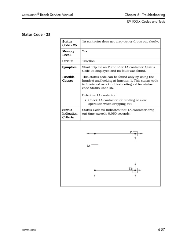
Mitsubishi EDR36 Forklift Service Manual
$50.00
- Type Of Manual: Service Manual
- Number of Pages: 296
- Size: 4.7MB
- Format: PDF
Product details
-
Model List:
- EDR36 Forklift
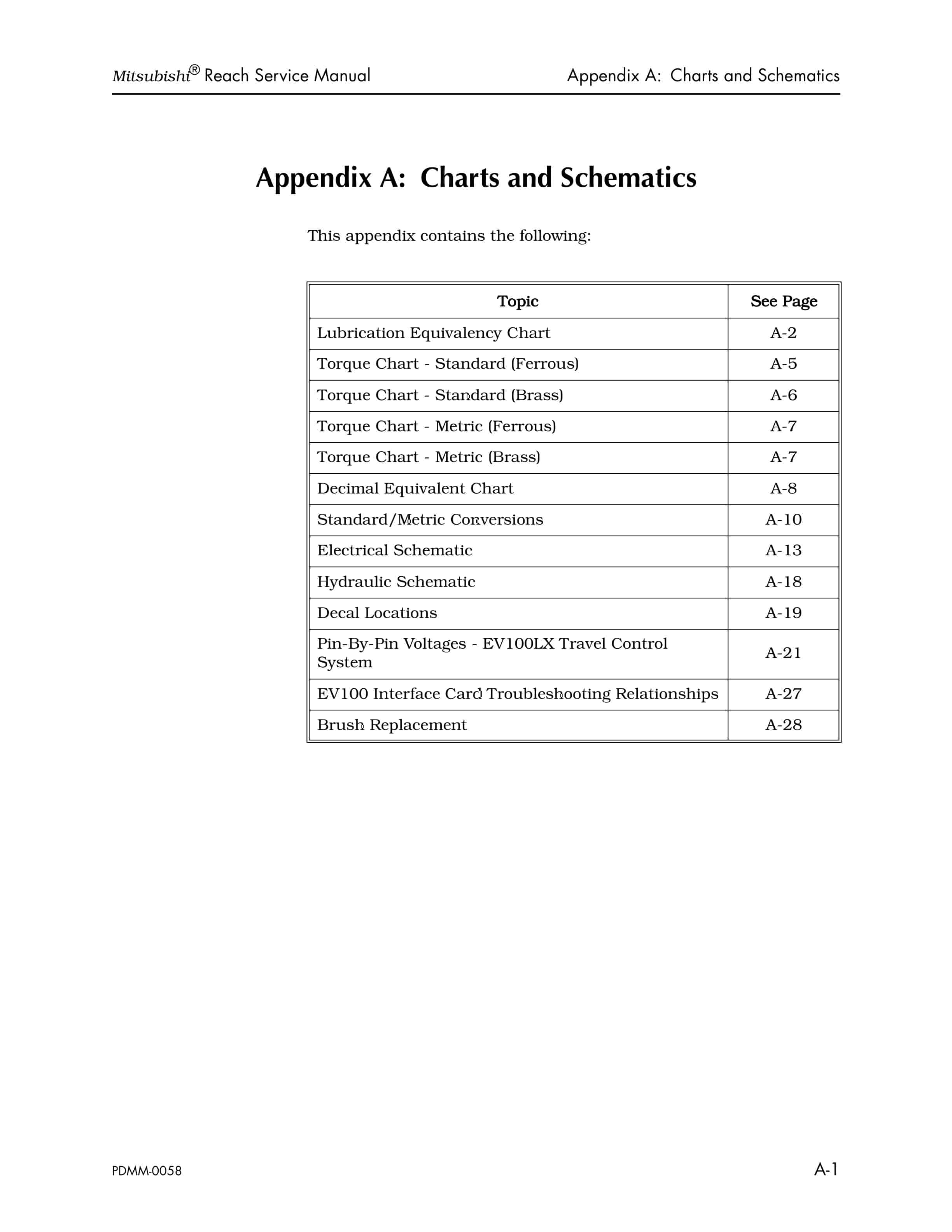
- 1. CHARTS AND SCHEMATICS
- 1.1. APPENDIX A CHARTS AND SCHEMATICS
- 1.1.1. Lubrication Equivalency Chart
- 1.1.2. Torque Chart – Standard (Ferrous)
- 1.1.3. Torque Chart – Standard (Brass)
- 1.1.4. Torque Chart – Metric (Ferrous)
- 1.1.5. Torque Chart – Metric (Brass)
- 1.1.6. Decimal Equivalent Chart
- 1.1.7. Standard/Metric Conversions
- 1.1.8. Electrical Schematic
- 1.1.9. Hydraulic Schematic
- 1.1.10. Decal Locations
- 1.1.11. Pin-By-Pin Voltages – EV100LX Travel Control System
- 1.1.12. EV100 Interface Card Troubleshooting Relationships
- 1.1.13. Brush Replacement
- 2. GENERAL INFORMATION
- 2.1. GENERAL INFORMATION
- 2.1.1. Warning Pages
- 2.1.2. Overview of this Manual
- 2.1.3. List of Figures
- 2.1.4. List of Tables
- 3. INSTALLATION
- 3.1. INSTALLATION
- 3.1.1. Overview
- 3.1.1.1. Warranty Coverage
- 3.1.1.2. In this Chapter
- 3.1.2. Inspecting the Truck
- 3.1.2.1. How the Truck is Shipped
- 3.1.2.2. Reasons for Doing a Visual Inspection
- 3.1.2.3. What to Look For
- 3.1.2.4. Repairing Shipping Damage
- 3.1.2.5. Repairing Defects
- 3.1.3. Uprighting a Cradled Truck
- 3.1.3.1. Warnings and Cautions
- 3.1.3.2. Items Needed
- 3.1.3.3. Option 1 Uprighting with Two Chain Hoists
- 3.1.3.4. Option 2 Uprighting with One Chain Hoist and a Lift Truck
- 3.1.4. Assembling the Truck
- 3.1.4.1. Removing the Gaskets
- 3.1.4.2. Greasing the Mast Uprights
- 3.1.4.3. Installing the Battery
- 3.1.5. Doing a Functional Inspection
- 3.1.5.1. Who Does the Inspection
- 3.1.5.2. What Needs to be Done
- 3.1.5.3. Starting the Mitsubishi Warranty
- 3.1.5.4. Reporting Repairs
- 3.1.5.5. Using the Checklist
- 3.1.6. Preparing the Truck for Cold Storage
- 3.1.6.1. Classes of Cold Storage
- 3.1.6.2. Types of Oil
- 3.1.6.3. Changing the Hydraulic System Oil
- 3.1.7. Preparing the Truck for Storage
- 3.1.7.1. Storage Warranty
- 3.1.7.2. General Storage Tips
- 3.1.7.3. Hydraulic System
- 3.1.7.4. Hydraulic Cylinders
- 3.1.7.5. Lift Chains
- 3.1.7.6. Mast Uprights
- 3.1.7.7. Electronics
- 3.1.7.8. Battery
- 4. MAINTENANCE
- 4.1. MAINTENANCE
- 4.1.1. General Maintenance Instructions
- 4.1.1.1. In this Chapter
- 4.1.2. Maintenance Practices
- 4.1.2.1. Jacking the Truck
- 4.1.2.2. Welding Procedures
- 4.1.2.2.1. Electrostatic Discharge Damage
- 4.1.2.2.2. Proper Handling of Static Sensitive Devices
- 4.1.2.2.3. Discharging the Truck
- 4.1.2.2.4. Removing the Circuit Card
- 4.1.2.2.5. Removing an Integrated Circuit (IC)
- 4.1.2.2.6. Installing a New Integrated Circuit
- 4.1.2.2.7. Removing a Pin
- 4.1.2.2.8. Troubleshooting with the Cable Connector Breakout Board
- 4.1.2.3. Shunt Locations
- 4.1.3. Planned Maintenance
- 4.1.3.1. Service Manual
- 4.1.3.2. Planned Maintenance Schedule
- 4.1.3.3. Time Requirements
- 4.1.3.4. Planned Maintenance Checks
- 4.1.3.4.1. Inspection Schedule
- 4.1.3.5. Grease Fitting Locations
- 4.1.4. Battery Maintenance
- 4.1.4.1. How Batteries Get Damaged
- 4.1.4.2. Removing a Battery
- 4.1.4.3. Installing a Battery
- 4.1.4.4. Cleaning the Battery
- 4.1.4.5. Testing the Battery Electrical Leakage To Frame
- 4.1.4.6. Battery Discharge Indicator (BDI)
- 4.1.4.6.1. Internal Resistance Compensation
- 4.1.4.6.2. Adjusting the Internal Compensation
- 4.1.4.7. Changing the Battery
- 4.1.4.7.1. Precautions
- 4.1.4.7.2. Using the Hydrometer
- 4.1.4.7.3. Checking the Specific Gravity
- 4.1.4.8. Voltage Check
- 4.1.4.9. Adding Water to the Battery
- 4.1.4.10. Keeping a Battery History Record
- 4.1.5. Maintaining the Motor
- 4.1.5.1. Motor Cleaning
- 4.1.5.2. Brush Care
- 4.1.5.2.1. Cleaning the Brushes
- 4.1.5.2.2. Measuring the Brush Spring Tension
- 4.1.5.2.3. Replacing a Brush
- 4.1.5.3. Preventing the Motor from Overheating
- 4.1.5.3.1. Checking the Torque on the Motor Stud Terminals
- 4.1.5.4. Open Circuits
- 4.1.5.4.1. Testing for Open Circuits
- 4.1.5.5. Short Circuits
- 4.1.5.5.1. Testing for Short Circuits
- 4.1.5.6. Armature Shorts
- 4.1.5.6.1. Checking for Armature Shorts
- 4.1.5.7. Grounded Motors
- 4.1.5.7.1. Testing for a Grounded Motor
- 4.1.5.8. Truck Grounds – General
- 4.1.5.8.1. Testing for Grounds on the Truck Frame
- 4.1.6. Hydraulic System Maintenance
- 4.1.6.1. Selecting the Oil
- 4.1.6.2. Changing the Reservoir Fluid
- 4.1.6.3. Checking the Reservoir Fluid Level
- 4.1.6.4. Changing the Reservoir Filter
- 4.1.6.5. Bleeding the Hydraulic System
- 4.1.7. Mechanical Maintenance
- 4.1.7.1. Power Section
- 4.1.7.1.1. Drive Unit Service
- 4.1.7.1.2. Removing the Drive Unit
- 4.1.7.1.3. Installing the Drive Unit
- 4.1.7.1.4. Preparing to Replace the Drive Axle Seal (36-Volt)
- 4.1.7.1.5. Replacing the Drive Axle Seal (36-Volt)
- 4.1.7.1.6. Preparing to Replace the Drive Axle Seal (24-Volt)
- 4.1.7.1.7. Disassembling the Drive Unit (24-Volt)
- 4.1.7.1.8. Assembling the Drive Unit (24-Volt)
- 4.1.7.2. Braking System
- 4.1.7.2.1. Braking Process
- 4.1.7.2.2. Adjusting Nut-Retained Style Brakes
- 4.1.7.2.3. Inspecting the Brake Pad
- 4.1.7.2.4. Bleeding the Brake
- 4.1.7.2.5. Adjusting the Deadman Pedal
- 4.1.7.2.6. Replacing the Brake Master Cylinder
- 4.1.7.2.7. Replacing the Brake Pads
- 4.1.7.2.8. Brake Installation
- 4.1.7.2.9. Reassembling the Brake
- 4.1.7.2.10. Replacing the Brake O-Ring Seal
- 4.1.7.3. Steering System
- 4.1.7.3.1. Steering Adjustment with Steerable Caster
- 4.1.7.3.2. Initial Adjustments
- 4.1.7.3.3. Adjusting the Casters
- 4.1.7.3.4. Service Notes for Steering Components
- 4.1.7.4. Lift/Lower System
- 4.1.7.4.1. Lift Chains
- 4.1.7.4.2. Removing and Inspecting the Chain
- 4.1.7.4.3. Lubricating the Lift Chain
- 4.1.7.4.4. Adjusting the Over the Mast Hose and Cable
- 4.1.7.4.5. Replacing the Over the Mast Hose
- 4.1.7.4.6. Replacing the Flow Control
- 4.1.7.4.7. Adjusting the Equalization Chain
- 4.1.7.4.8. Equalization Chain Removal and Installation
- 4.1.7.4.9. Replacing the Equalization Chain Sheave
- 4.1.7.4.10. Applying Loctite to the Reach Carriage Chain Anchors
- 4.1.7.4.11. Adjusting the Mechanical Stop
- 4.1.7.4.12. Reach Carriage Lubrication Points
- 4.1.7.4.13. Removing the Fork Carriage Tilt Pins
- 4.1.7.4.14. Attaching the Mast to the Tractor
- 4.1.7.4.15. Adjusting the High Pressure Relief Valve
- 5. OPERATING INSTRUCTIONS
- 5.1. OPERATING INSTRUCTIONS
- 5.1.1. In this Chapter
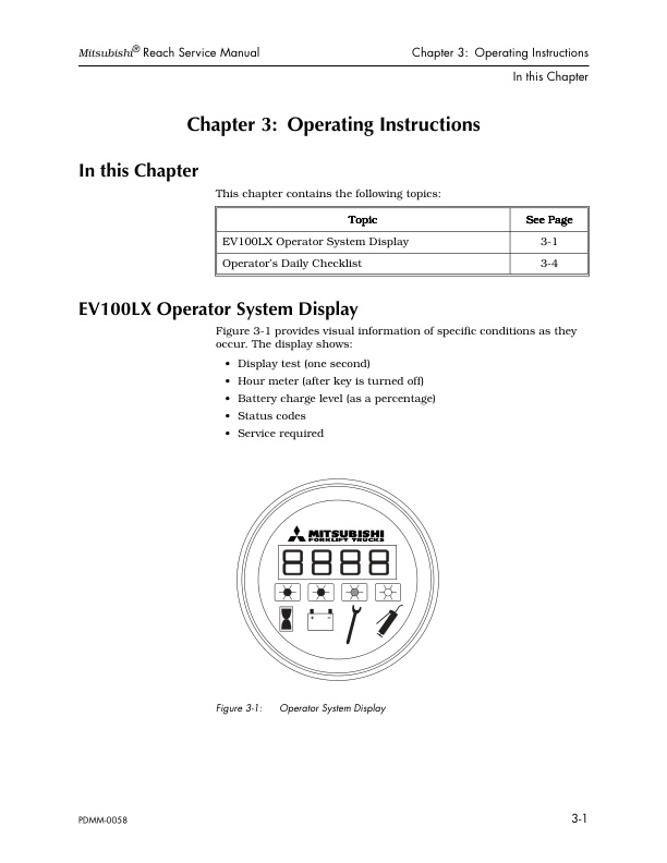
- 5.1.2. EV100LX Operator System Display
- 5.1.2.1. Display Test
- 5.1.2.2. Hour Meter
- 5.1.2.3. Battery Charge Level
- 5.1.2.4. Status Codes
- 5.1.2.4.1. Informational Messages
- 5.1.2.4.2. Performance Limiting Codes
- 5.1.2.4.3. Fault Codes
- 5.1.3. Operators Daily Checklist
- 5.1.3.1. Visual Checks
- 5.1.3.2. Operational Checks
- 5.1.3.2.1. Start-up Procedure
- 5.1.3.2.2. Forward/Reverse Travel
- 5.1.3.2.3. Braking
- 5.1.3.2.4. Plugging
- 5.1.3.2.5. Parking
- 5.1.3.2.6. Entering an Aisle
- 5.1.3.2.7. Operating the Truck on a Ramp
- 5.1.3.2.8. Travel Speed and Lift Limits
- 6. THEORY OF OPERATION
- 6.1. THEORY OF OPERATION
- 6.1.1. In this Chapter
- 6.1.2. EV100LX Control Panel
- 6.1.3. System Components
- 6.1.3.1. Silicon Controlled Rectifiers (SCR)
- 6.1.3.1.1. 1 Rectifier (REC1) Chopper SCR
- 6.1.3.1.2. 2 Rectifier (REC2) Commutating SCR
- 6.1.3.1.3. 5 Rectifier (REC5) Charging SCR
- 6.1.3.2. Diode Rectifiers
- 6.1.3.2.1. 3 Rectifier (REC3) Free Wheeling
- 6.1.3.2.2. 4 Rectifier (REC4) Plugging
- 6.1.3.2.3. Reactor (Coil T3/T4)
- 6.1.3.2.4. Capacitor 1-C
- 6.1.3.2.5. Filters REC22, REC23, REC24, REC25
- 6.1.3.3. Thermal Protector (TP)
- 6.1.3.4. Sensor (Sensor 1)
- 6.1.4. Control Features
- 6.1.4.1. Creep Speed
- 6.1.4.2. Controlled Acceleration
- 6.1.4.3. Current Limit
- 6.1.4.4. Plugging
- 6.1.4.5. Current Dropout
- 6.1.4.6. Speed Limit 1 (SL1) and Speed Limit 3 (SL3)
- 6.1.4.7. Static Return to OFF
- 6.1.4.8. Accelerator Volts Hold-Off
- 6.1.4.9. Coil Driver Modules
- 6.1.4.10. Thermal Cutback
- 6.1.4.11. Pulse Monitor Trip (PMT)
- 6.1.4.12. Internal Resistance Compensation
- 6.1.4.13. Steer Pump Time Delay
- 6.1.4.14. Stored Fault Code
- 6.1.4.15. Battery Discharge Indicator
- 6.1.4.16. Hour Meter
- 6.1.4.17. On-board Diagnostics
- 6.1.5. Basic SCR Controller Circuit Operation
- 6.1.5.1. Energizing the Control Circuit
- 6.1.5.2. Gate Pulse to REC2
- 6.1.5.3. Gate Pulse to REC1
- 6.1.5.4. Firing REC2
- 6.1.5.5. OFF Time
- 6.1.5.6. Oscillation Frequency
- 6.1.5.7. Oscillator Features
- 6.1.6. Wiring Conventions
- 6.1.7. Operation of the Travel System
- 6.1.7.1. Sequence 1 Truck at Rest
- 6.1.7.2. Sequence 2 Connect the Battery
- 6.1.7.3. Sequence 3 Closing the Key Switch and the Deadman Pedal
- 6.1.7.4. Sequence 4 PMT Test
- 6.1.7.5. Sequence 5 Directional Contactor Closure
- 6.1.7.6. Sequence 6 REC1 Turn ON
- 6.1.7.7. Sequence 7 REC5 Turn ON
- 6.1.7.8. Sequence 8 Reverse Charging the 1C Capacitor
- 6.1.7.9. Sequence 9 REC2 Turn ON and REC1 Turn OFF
- 6.1.7.10. Sequence 10 Free-Wheeling Current
- 6.1.7.11. Sequence 11 1A or Bypass Contactor Operation
- 6.1.7.12. Sequence 12 Controlled Plugging
- 6.1.8. Lift/Lower System
- 6.1.8.1. System Overview
- 6.1.8.2. Unique System Features
- 6.1.8.3. Components
- 6.1.8.4. Functionality
- 6.1.9. Braking
- 7. TROUBLESHOOTING
- 7.1. TROUBLESHOOTING
- 7.1.1. In this Chapter
- 7.1.2. Troubleshooting Procedure
- 7.1.2.1. Verifying Problems
- 7.1.2.2. Locating the Problem Area
- 7.1.2.3. Establishing a Logical Testing Sequence
- 7.1.2.4. Identifying the Cause of the Problem
- 7.1.2.5. Correcting the Problem
- 7.1.3. Electrical
- 7.1.3.1. Checking the Wiring
- 7.1.3.1.1. Troubleshooting Procedure
- 7.1.3.1.2. Shorts to the Truck Frame – Causes
- 7.1.3.1.3. Shorts to the Truck Frame – Checking
- 7.1.3.1.4. Voltage To Frame – Causes
- 7.1.3.1.5. Voltage To Frame – Checking
- 7.1.3.1.6. Voltage To Frame – Eliminating
- 7.1.3.2. Board and Component Swapping Precautions
- 7.1.3.2.1. Troubleshooting Order for Component Failure
- 7.1.3.2.2. Handling Printed Circuit Cards
- 7.1.3.2.3. Cleaning and Inspecting the Contactors
- 7.1.3.2.4. Contactors Specifications
- 7.1.3.2.5. Testing Other Electrical Components
- 7.1.3.2.6. EV100LX Component Tests
- 7.1.4. Hydraulics
- 7.1.4.1. Checking for Hydraulic Leaks
- 7.1.4.2. Maintenance Tips
- 7.1.4.2.1. Avoiding Hydraulic Problems
- 7.1.4.2.2. Lift/Lower Hydraulic System Troubleshooting
- 7.1.4.2.3. Steps for Locating Problems in the Lift/Lower System
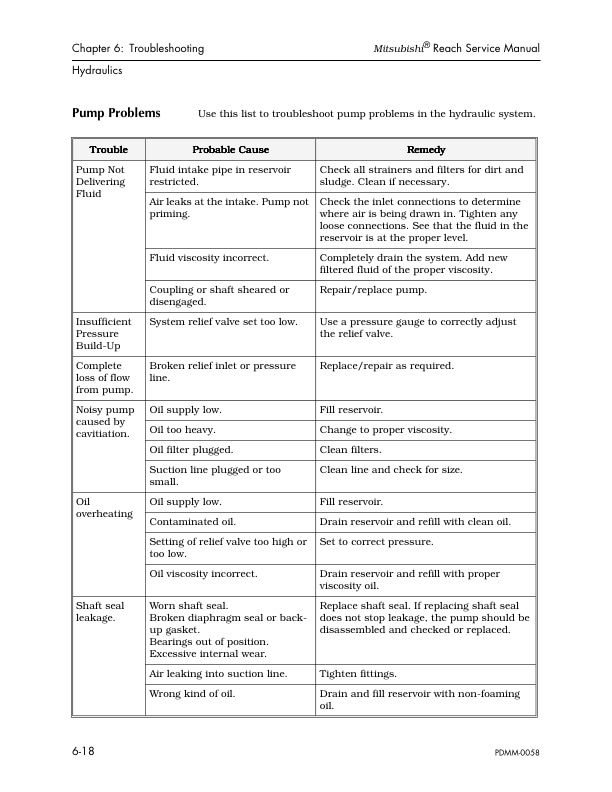
- 7.1.4.2.4. Pump Problems
- 7.1.5. EV100LX Codes and Tests
- 7.1.5.1. Troubleshooting the EV100LX Solid-State Control System
- 7.1.5.1.1. Identifying a Malfunction
- 7.1.5.1.2. Replacing the Logic Card
- 7.1.5.1.3. Wire Numbers
- 7.1.5.1.4. Jacking the Truck
- 7.1.5.1.5. Accessing the Terminals
- 7.1.5.1.6. Visual Check
- 7.1.5.2. Using the LX Handset
- 7.1.5.2.1. Operating the Handset
- 7.1.5.2.2. Function Set-Up Procedures
- 7.1.5.2.3. Handset Programmable Functions
- 7.1.5.2.4. System Voltage Drop vs. Function Setting
- 7.1.5.3. GE Status Codes
- 7.1.5.3.1. Status Code – Blank display
- 7.1.5.3.2. Status Code – 01
- 7.1.5.3.3. Status Code – 02
- 7.1.5.3.4. Status Code – 03
- 7.1.5.3.5. Status Code – 04
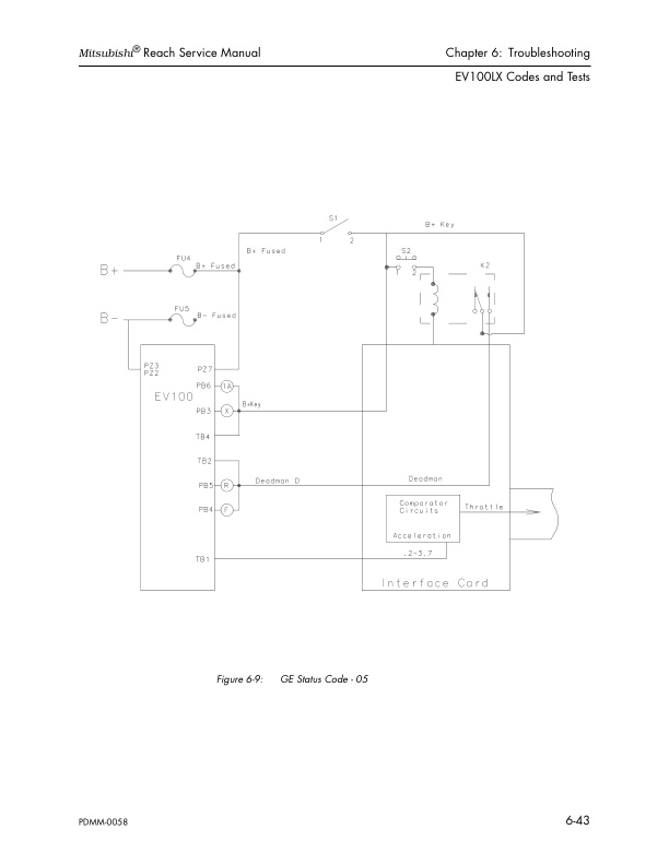
- 7.1.5.3.6. Status Code – 05
- 7.1.5.3.7. Status Code – 06
- 7.1.5.3.8. Status Code – 07
- 7.1.5.3.9. Status Code – 08
- 7.1.5.3.10. Status Code – 09
- 7.1.5.3.11. Status Code – 15
- 7.1.5.3.12. Status Code – 16
- 7.1.5.3.13. Status Code – 17
- 7.1.5.3.14. Status Code – 23
- 7.1.5.3.15. Status Code – 24
- 7.1.5.3.16. Status Code – 25
- 7.1.5.3.17. Status Code – 41
- 7.1.5.3.18. Status Code – 42
- 7.1.5.3.19. Status Code – 43
- 7.1.5.3.20. Status Code – 44
- 7.1.5.3.21. Status Code – 45
- 7.1.5.3.22. Status Code – 46
- 7.1.5.3.23. Status Code – 47
- 7.1.5.3.24. Status Code – 48
- 7.1.5.3.25. Status Code – 49
- 7.1.5.3.26. Status Code – 50
- 7.1.5.3.27. Status Code – 51
- 7.1.5.3.28. Status Code – 52
- 7.1.5.3.29. Status Code – 53
- 7.1.5.3.30. Status Code – 54
- 7.1.5.3.31. Status Code – 57
- 7.1.6. Troubleshooting the Interface Card System
- 7.1.6.1. Running Learn
- 7.1.6.2. Setting up the Truck
- 7.1.6.3. Interface Card Switch Settings
- 7.1.6.4. Interface Card Assembly
- 7.1.6.5. Interface Card Codes
- 7.1.7. Troubleshooting the Interface Card
- 7.1.7.1. Display on Interface Card is Dark
- 7.1.7.2. No Auxiliary Functions Aux. Motor Runs Other Functions OK
- 7.1.7.3. Auxiliary Motor Does not Run Other functions OK
- 7.1.7.4. One Auxiliary Function Is Inoperative
- 7.1.7.5. Auxiliary Functions Operate In Only One Direction Steering OK
- 7.1.7.5.1. No Lift
- 7.1.7.5.2. No Lower
- 7.1.7.6. No Travel, Other Functions OK
- 7.1.7.7. No Speed Limit
- 7.1.7.8. No Lift Inhibit
- 8. TRUCK DESCRIPTION
- 8.1. TRUCK DESCRIPTION
- 8.1.1. Overview
- 8.1.1.1. In this Chapter
- 8.1.2. Truck Overview
Related products
-
Mitsubishi 4DQ5, S4E, S6E, S6E2 Service Manual 99719-52120
$50.00 Add to cart -
Mitsubishi 4G15 Gasoline Engine Service Manual 99719-16110
$50.00 Add to cart -
Mitsubishi 1204E Diesel Engine Specifications Service Manual 99799-56101
$50.00 Add to cart -
Mitsubishi 4G63, 4G64 Fuel System Supplement Service Manual 99729-75110
$50.00 Add to cart -
Mitsubishi 2FBC30 Forklift Service Manual
$50.00 Add to cart


