

Mitsubishi FB161820KT Forklift Service Manual
$50.00
- Type Of Manual: Service Manual
- Number of Pages: 478
- Size: 39.4MB
- Format: PDF
Product details
-
Model List:
- FB161820KT Forklift
- 1. GENERAL INFORMATION
- 1.1. GENERAL INFORMATION
- 1.1.1. Vehicle Exterior
- 1.1.2. Serial Number Locations
- 1.1.3. Chassis and Mast Model Identification
- 1.1.4. Dimensions
- 1.1.5. Technical Data
- 2. BRAKE SYSTEM
- 2.1. BRAKE SYSTEM
- 2.1.1. Specifications
- 2.1.2. Structure and Functions
- 2.1.2.1. Caliper Assembly
- 2.1.2.2. Brake Pedal Assembly
- 2.1.2.3. Master Cylinder
- 2.1.2.4. Parking Brake Lever
- 2.1.3. Procedures and Suggestions for Disassembly and Reassembly
- 2.1.3.1. Master Cylinder
- 2.1.4. Inspection and Adjustment
- 2.1.4.1. Pad Clearance Adjustment
- 2.1.4.2. Brake Pedal Adjustment
- 2.1.4.3. Brake Switch Installation
- 2.1.4.4. Brake Fluid Line Bleeding
- 2.1.4.5. Parking Brake Adjustment
- 2.1.5. Troubleshooting
- 2.1.6. Service Data
- 3. HYDRAULIC SYSTEM
- 3.1. HYDRAULIC SYSTEM
- 3.1.1. Specifications
- 3.1.2. Structure and Functions
- 3.1.2.1. Hydraulic Line
- 3.1.2.2. Control Valve
- 3.1.2.3. Lift and Tilt Cylinders
- 3.1.2.4. Flow Regulator Valve
- 3.1.2.5. Down Safety Valve
- 3.1.3. Gear Pump
- 3.1.3.1. Procedures and Suggestions for Removal and Installation
- 3.1.4. Control Valve
- 3.1.4.1. Procedures and Suggestions for Removal and Installation
- 3.1.4.2. Procedures and Suggestions for Disassembly and Reassembly
- 3.1.5. Lift Cylinders
- 3.1.5.1. Procedures and Suggestions for Removal and Installation
- 3.1.5.2. Procedures and Suggestions for Disassembly and Reassembly
- 3.1.6. Tilt Cylinders
- 3.1.6.1. Procedures and Suggestions for Removal and Installation
- 3.1.6.2. Procedures and Suggestions for Disassembly and Reassembly
- 3.1.7. Flow Regulator Valve
- 3.1.7.1. Procedures and Suggestions for Disassembly and Reassembly
- 3.1.8. Suction Strainer and Return Filter
- 3.1.8.1. Procedures and Suggestions for Removal and Installation
- 3.1.9. Inspection and Adjustment
- 3.1.9.1. Hydraulic Tank
- 3.1.9.2. Control Valve
- 3.1.9.3. Lift Cylinders and Tilt Cylinders
- 3.1.9.4. Adjustment Values of Microswitches
- 3.1.9.5. Procedures for Adjusting Microswitches
- 3.1.10. Hydraulic Circuit Diagram
- 3.1.11. Hydraulic Circuits
- 3.1.12. Troubleshooting
- 3.1.13. Service Data
- 4. MAST AND FORKS
- 4.1. MAST AND FORKS
- 4.1.1. Mast Systems
- 4.1.1.1. Mast Type Code Stamping Position
- 4.1.1.2. Explanation of Mast Type Code
- 4.1.1.3. Mast Types
- 4.1.2. Description
- 4.1.2.1. Dual-stage Panoramic Mast (Simplex Mast)
- 4.1.2.2. Dual-stage Full Free Panoramic Mast (Duplex Mast)
- 4.1.2.3. Triple-stage Full Free Panoramic Mast (Triplex Mast)
- 4.1.2.4. Operation of Dual-stage Full Free Panoramic Mast
- 4.1.2.5. Operation of Triple-stage Full Free Panoramic Mast
- 4.1.3. Removal and Installation
- 4.1.3.1. Mast and Lift Bracket Assembly
- 4.1.4. Disassembly and Reassembly
- 4.1.4.1. Dual-stage Panoramic Mast (Simplex Mast)
- 4.1.4.2. Dual-stage Full Free Panoramic Mast (Duplex Mast)
- 4.1.4.3. Triple-stage Full Free Panoramic Mast (Triplex Mast)
- 4.1.5. Inspection and Adjustment
- 4.1.5.1. Chain Tension Adjustment
- 4.1.5.2. Clearance Adjustment on Lift Bracket
- 4.1.5.3. Mast Clearance Adjustment
- 4.1.5.4. Main Roller Shim Replacement
- 4.1.5.5. Mast Strip Adjustment
- 4.1.5.6. Tilt Angle Adjustment
- 4.1.5.7. Lift Cylinder Stroke Adjustment
- 4.1.6. Troubleshooting
- 4.1.7. Service Data
- 4.1.8. Motor Installation Positions
- 4.1.9. Specifications
- 4.1.10. Structures
- 4.1.11. Tightening of High-power Cable Terminals
- 4.1.12. Inspection of Brushes for Wear and Brush Replacement
- 4.1.13. Procedures and Suggestions for Removal and Installation
- 4.1.14. Procedures and Suggestions for Disassembly and Reassembly
- 4.1.15. Troubleshooting
- 4.1.16. Service Data
- 4.1.17. Checks and Repairs
- 5. Options Supplement
- 5.1. FORWORD
- 5.2. AMBER STROBE KIT
- 5.3. BACK BUZZER KIT
- 5.4. HEAD LAMP KIT (48 V AND 36 V) (Not applicable to EU models)
- 5.5. REARVIEW MIRROR KIT (Not applicable to EU models)
- 5.6. ADDITIONAL-ON CONTROL VALVE KIT (For MC model)
- 5.7. FOOT-OPERATED DIRECTION CONTROL KIT (Not applicable to US EE model)
- 5.8. EE MODEL AND EE UNCOVERED BATTERY MODEL (US EE model)
- 6. OPTIONS
- 6.1. OPTIONS
- 6.1.1. Rearview Mirror Kit
- 6.1.2. Backup Buzzer Kit
- 6.1.3. Working Lamp Kit
- 6.1.4. Tire Kit (Solid)
- 6.1.5. Tire Kit (Nonmarking Cushion)
- 6.1.6. Foot Direction Control Kit
- 7. POWER TRAIN
- 7.1. POWER TRAIN
- 7.1.1. Procedures and Suggestions for Removal and Installation
- 7.1.1.1. Removal
- 7.1.1.2. Installation
- 7.1.2. Service Data
- 8. REAR AXLE
- 8.1. REAR AXLE
- 8.1.1. Structure and Functions
- 8.1.1.1. Rear Wheels
- 8.1.2. Procedures and Suggestions for Removal and Installation
- 8.1.2.1. Rear Wheels
- 8.1.2.2. Rear Axle
- 8.1.3. Procedures and Suggestions for Disassembly and Reassembly
- 8.1.3.1. Steering Axle
- 8.1.3.2. Rear Axle Assembly
- 8.1.4. Inspection and Adjustment
- 8.1.4.1. Making sure of Minimum Turning Radius
- 8.1.5. Service Data
- 9. SERVICE DATA
- 9.1. SERVICE DATA
- 9.1.1. Inspection Standards
- 9.1.2. Periodic Replacement of Parts
- 9.1.2.1. Critical Safety Parts
- 9.1.3. Lubricating Standards
- 9.1.3.1. Lubrication Chart
- 9.1.3.2. Lubricant Quantities
- 9.1.3.3. Recommended Lubricant
- 9.1.4. Main Component Weights
- 9.1.5. Tightening Torques for Standard Bolts and Nuts
- 9.1.6. Special Tool Table
- 10. STEERING SYSTEM
- 10.1. STEERING SYSTEM
- 10.1.1. Specifications
- 10.1.2. Structure and Functions
- 10.1.2.1. General
- 10.1.2.2. Steering Control Valve
- 10.1.3. Procedures and Suggestions for Removal and Installation
- 10.1.3.1. Steering Column Assembly
- 10.1.4. Steering Control Valve
- 10.1.4.1. Disassembly
- 10.1.4.2. Inspection
- 10.1.4.3. Reassembly
- 10.1.5. Hydraulic Circuit Diagram
- 10.1.6. Troubleshooting
- 10.1.7. Service Data
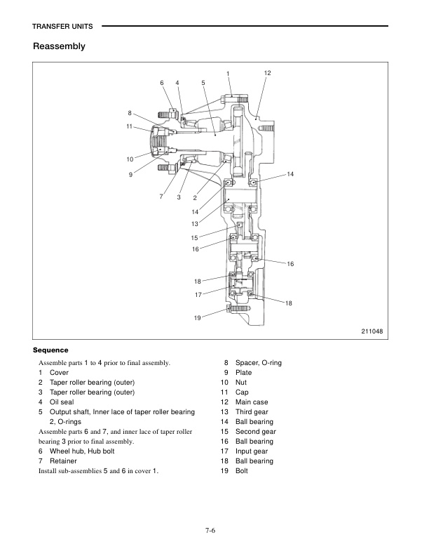
- 11. TRANSFER UNITS
- 11.1. TRANSFER UNITS
- 11.1.1. Specifications
- 11.1.2. Structure and Functions
- 11.1.3. Procedures and Suggestions for Disassembly and Reassembly
- 11.1.3.1. Disassembly
- 11.1.3.2. Inspection after Disassembly
- 11.1.3.3. Reassembly
- 11.1.4. Service Data
- 12. VEHICLE ELECTRICAL COMPONENTS
- 12.1. VEHICLE ELECTRICAL COMPONENTS
- 12.1.1. Console Box
- 12.1.1.1. Functions of Central Vehicle Monitor System
- 12.1.1.2. Electrical Components in Console Box
- 12.1.1.3. Disassembly and Reassembly
- 12.1.2. Direction Lever
- 12.1.3. Accelerator Control
- 12.1.4. Key Switch
- 12.1.5. Lighting Switch
- 12.1.6. Lamp Specification Chart
- 12.1.7. Troubleshooting of Lighting and Horn Systems
- 13. Chassis, Mast, Options
- 13.1. SERVICE MANUAL CHASSIS, MAST, AND OPTIONS
- 13.1.1. FOREWORD
- 13.1.2. HOW TO USE THIS MANUAL
- 13.1.3. GROUP INDEX
- 14. MAIN CONTROLLER
- 14.1. MAIN CONTROLLER
- 14.1.1. Outline
- 14.1.2. Controller Components (Part 1)
- 14.1.3. Controller Components (Part 2)
- 14.1.4. Logic Card Components
- 14.1.5. Controller Models
- 14.1.6. Operation Outline
- 14.1.7. Drive System
- 14.1.7.1. Neutral Position
- 14.1.7.2. Powering
- 14.1.7.3. Drive Motors Current Table (48 V type)
- 14.1.7.4. Drive Motors Current Table (36 V type)
- 14.1.7.5. Regeneration
- 14.1.7.6. Steering and Turns
- 14.1.7.7. Lever Regeneration Characteristic (48 V type)
- 14.1.7.8. Lever Regeneration Characteristic (36 V type and EE option type)
- 14.1.7.9. Auto Regeneration Characteristic (48 V type)
- 14.1.7.10. Auto Regeneration Characteristic (36 V type and EE option type)
- 14.1.7.11. Steering Characteristic (1.6 ton type)
- 14.1.7.12. Steering Characteristic (1.8 ton type)
- 14.1.7.13. Steering Characteristic (2.0 ton type)
- 14.1.8. Hydraulic System
- 14.1.8.1. Chopper Model
- 14.1.8.2. Contactor Model
- 14.1.9. Fail-safe System
- 14.1.9.1. Output Power Control at Low Battery Voltage
- 14.1.9.2. Overheat
- 14.1.9.3. Brush Wear
- 14.1.9.4. Maximum Vehicle Speed Control (SUO 7)
- 14.1.9.5. Output Power Control During Braking
- 14.1.9.6. Chat Timer (SUO 24)
- 14.1.9.7. Seat Switch Timer (SUO 25)
- 14.1.10. Malfunction Detection (Run Time Diagnosis)
- 14.1.11. Malfunction Data Record (History Folder)
- 14.1.11.1. Data Storage
- 14.1.11.2. Review of Stored Data
- 14.1.12. Setting
- 14.1.12.1. Printed Circuit Board Settings
- 14.1.12.2. Adjustment of Remaining Battery Level
- 14.1.12.3. Setup Options
- 14.1.13. Self-diagnosis
- 14.1.14. Other Functions
- 14.1.15. Display Unit
- 14.1.15.1. BDI (Battery Discharge Indicator)
- 14.1.15.2. Hourmeters and Time Display
- 14.1.15.3. Vehicle Speed and Error Code Display
- 14.1.15.4. Action Lights (LEDs)
- 14.1.16. Inspection and Adjustment
- 14.1.16.1. Inspection and Adjustment Tools
- 14.1.16.2. Removal and Installation of Logic Card
- 14.1.16.3. Tightening of High-tension Cable Terminals
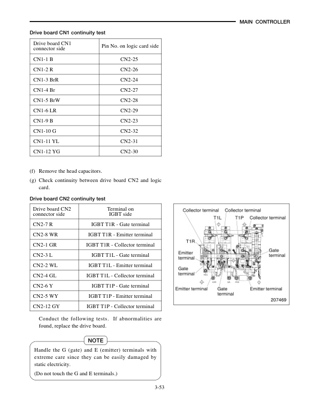
- 14.1.16.4. Component Testing
- 14.1.17. Service Data
- 14.1.18. Tightening Torque
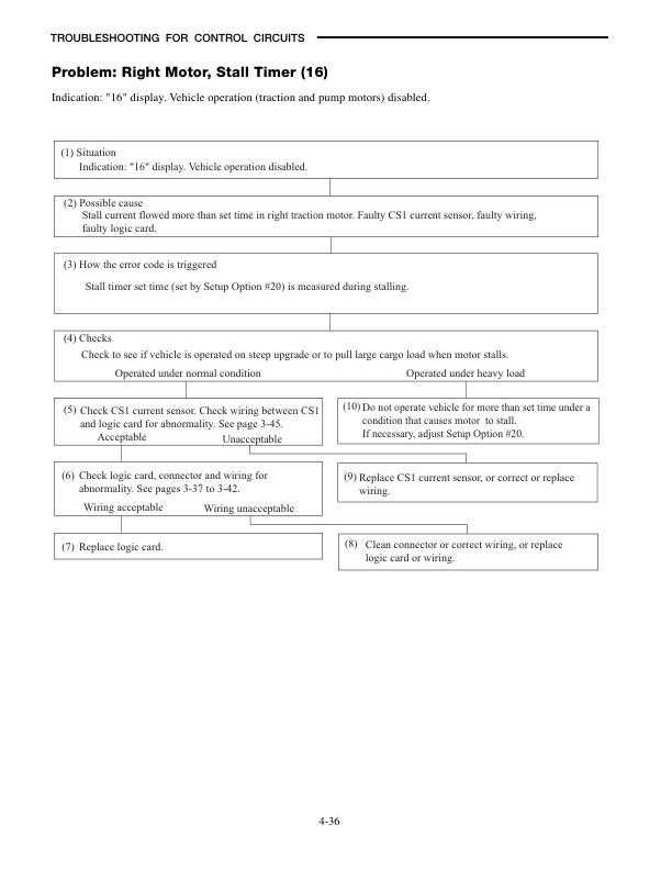
- 15. TROUBLESHOOTING FOR CONTROL CIRCUITS
- 15.1. TROUBLESHOOTING FOR CONTROL CIRCUITS
- 15.1.1. General Information
- 15.1.2. Alarm List
- 15.1.3. E0 Right Motor,Overheating
- 15.1.4. E1 Left Motor,Overheating
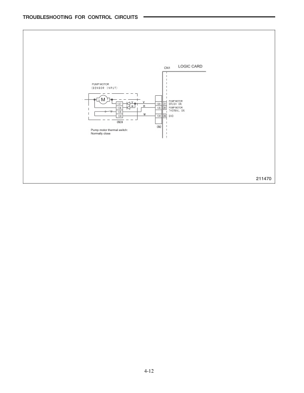
- 15.1.5. E2 Pump Motor,Overheating
- 15.1.6. E3 Controller,Overheating
- 15.1.7. E4 Right Motor,Worn Brushes
- 15.1.8. E5 Left Motor,Worn Brushes
- 15.1.9. E6 Pump Motor,Worn Brushes
- 15.1.10. Brake Oil,Low Level
- 15.1.11. Right Motor,Faulty Armature Circuit
- 15.1.12. Right Motor,Transistor Wire Breakage
- 15.1.13. Right Motor,Shorted Transistor
- 15.1.14. Right Motor,Faulty Transistor Drive
- 15.1.15. Right Motor,Faulty Current Sensor
- 15.1.16. Right Motor,Armature Over-current
- 15.1.17. Right Motor,Stall Timer
- 15.1.18. Right Motor,Faulty Field Circuit
- 15.1.19. Right Motor,Faulty Field Drive
- 15.1.20. Right Motor,Field Over-current
- 15.1.21. Left Motor,Faulty Armature Circuit
- 15.1.22. Left Motor,Transistor Wire Breakage
- 15.1.23. Left Motor,Shorted Transistor
- 15.1.24. Left Motor,Faulty Transistor Drive
- 15.1.25. Left Motor,Faulty Current Sensor
- 15.1.26. Left Motor,Armature Over-current
- 15.1.27. Left Motor,Stall Timer
- 15.1.28. Left Motor,Faulty Field Circuit
- 15.1.29. Left Motor,Faulty Field Drive
- 15.1.30. Left Motor,Field Over-current
- 15.1.31. Pump Motor,Faulty Circuit
- 15.1.32. Pump Motor,Transistor Wire Breakage
- 15.1.33. Pump Motor,Shorted Transistor
- 15.1.34. Pump Motor,Faulty Transistor Drive
- 15.1.35. Pump Motor,Faulty Current Sensor
- 15.1.36. Pump Motor,Armature Over-current
- 15.1.37. Line Contactor,Abnormality
- 15.1.38. Regeneration Contactor,Abnormality
- 15.1.39. Pump Contactor,Abnormality
- 15.1.40. Regeneration Diode,Abnormality
- 15.1.41. Right Armature Diode,Abnormality
- 15.1.42. Left Armature Diode,Abnormality
- 15.1.43. Pump Armature Diode,Abnormality
- 15.1.44. Right Motor,Wire Breakage
- 15.1.45. Left Motor,Wire Breakage
- 15.1.46. Pump Motor,Wire Breakage
- 15.1.47. Steering Sensor,Abnormality
- 15.1.48. Accelerator,Abnormality
- 15.1.49. Right Vehicle Speed Sensor,Abnormality
- 15.1.50. Left Vehicle Speed Sensor,Abnormality
- 15.1.51. E Direction Lever and Accelerator,Faulty Setting
- 15.1.52. (E)Seat Switch,Faulty Setting
- 15.1.53. H1 Lift Lever,Faulty Setting
- 15.1.54. H2 Tilt Lever,Faulty Setting
- 15.1.55. H3 Attachment 1 Lever,Faulty Setting
- 15.1.56. H4 Attachment 2 Lever,Faulty Setting
- 15.1.57. Data Communication,Abnormality
- 15.1.58. EEPROM,Abnormality
- 15.1.59. Logic Card,Faulty Initial Setting
- 15.1.60. Controller,Abnormality
- 15.1.61. Battery Voltage,Excessively Low (For 48-V Vehicles Only)
- 15.1.62. Battery Voltage,Excessively High (For 36-V Vehicles Only)
Related products
-
Mitsubishi 1204E Diesel Engine Operation and Maintenance Manual Service Manual 99799-56105
$50.00 Add to cart -
Mitsubishi PSI 4X LPG Engine Service Manual 99739-7C100
$50.00 Add to cart -
Mitsubishi 4DQ5, S4E, S4E2 Diesel Engine Service Manual
$50.00 Add to cart -
Mitsubishi 4G15 Gasoline Engine Service Manual 99719-16110
$50.00 Add to cart -
Mitsubishi 1204E Diesel Engine Systems Operation Testing and Adjusting Service Manual 99799-56103
$50.00 Add to cart


