

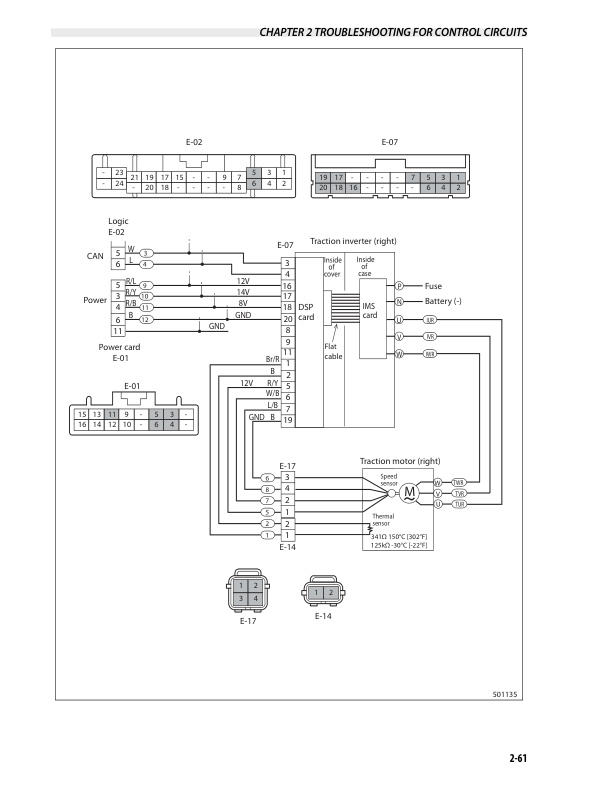
Mitsubishi FB16PNT, FB18PNT, FB20PNT Controller Service Manual 99759-7P100
$50.00
- Type Of Manual: Service Manual
- Manual ID: 99759-7P100
- Number of Pages: 272
- Size: 13.6MB
- Format: PDF
Product details
-
Model List:
- FB16PNT, FB18PNT, FB20PNT
- 1. FOREWORD
- 1.1.
- 1.2. Safety
- 1.3. How to Use This Manual
- 1.4. Units
- 1.4.1. Chapter 1 CONTROLLER
- 1.4.2. Chapter 2 TROUBLESHOOTING FOR CONTROL CIRCUITS
- 1.4.3. Chapter 3 MOTOR
- 1.4.4. Chapter 4 HOW TO READ CIRCUIT DIAGRAMS
- 1.4.5. Chapter 5 CIRCUIT DIAGRAM
- 2. Chapter 1 CONTROLLER
- 2.1. Controller System
- 2.1.1. System Layout
- 2.1.2. Controller Area Network (CAN)
- 2.1.3. Outline of Logic Unit
- 2.1.4. Outline of Inverter
- 2.1.5. Outline of EPS Controller
- 2.2. Traction Controller Feature
- 2.2.1. Modification of Traction Characteristics
- 2.2.2. Anti-rollback
- 2.2.3. Boost
- 2.2.4. Limitation of Maximum Travel Speed
- 2.2.5. Controlled Cornering Speed
- 2.2.6. Miscellaneous Features for Traction
- 2.3. Lifting Controller Feature
- 2.3.1. Setting and Limitation of Lift work Speed
- 2.3.2. Lift Stop
- 2.4. Other Feature
- 2.4.1. IPS (Integrated Presence System) Feature
- 2.4.2. Display Function
- 2.4.3. Parking Brake Interlock
- 2.4.4. BDI (Battery Discharge Indicator) Display Features
- 2.4.5. Miscellaneous Features
- 2.4.6. Hour Meter
- 2.5. Setup Option
- 2.5.1. Outline
- 2.5.2. Details of Setup Options (Group-1)
- 2.5.3. Details of Setup Options (Group-2)
- 2.5.4. Details of Setup Options (Group-3)
- 2.5.5. Setup Options (Group 1)
- 2.5.6. Setup Options (Group 2)
- 2.5.7. Setup Options (Group 3)
- 2.6. Diagnostics
- 2.6.1. Outline
- 2.6.2. Operation Procedure
- 2.6.3. Self-Diagnostics
- 2.6.4. Power Steering Diagnostics
- 2.6.5. Run Time Diagnostics
- 2.6.6. Fail-Safe Restriction List
- 2.7. Removal and Installation
- 2.7.1. Inverter Discharging Procedure
- 2.7.2. Replacing Inverter
- 2.7.3. Replacing DSP (Digital Signal Processor) Card
- 2.7.4. Replacing Logic Unit
- 2.7.5. Replacing EPS Controller
- 2.7.6. Replacing Logic Card
- 2.7.7. Replacing Power Supply Card
- 2.8. Basic Check
- 2.8.1. Testing Tools
- 2.8.2. Measurement of Card Voltage
- 2.8.3. Checking Contactor Coil
- 2.8.4. Checking Contactor Tips
- 2.8.5. Checking Inverter
- 2.8.6. Regeneration Check
- 2.9. AC Motor System Basics
- 2.9.1. Feature of AC motor
- 2.9.2. Speed control of Induction Motors
- 2.9.3. Inverter
- 3. Chapter 2 TROUBLESHOOTING FOR CONTROL CIRCUITS
- 3.1. General Information
- 3.1.1. Before Replacing Devices
- 3.1.2. Connection of the service tool
- 3.1.3. How to Clean Harness Connectors and System Components
- 3.2. List of Error Codes
- 3.3. Troubleshooting
- 3.3.1. Traction Motor R.H.,Overheating (E0)
- 3.3.2. Traction Motor L.H.,Overheating (E1)
- 3.3.3. Pump Motor,Overheating(E2)
- 3.3.4. Traction Inverter R.H., Overheating (E5)
- 3.3.5. Traction Inverter L.H., Overheating (E6)
- 3.3.6. Pump Inverter, Overheating (E7)
- 3.3.7. PS Controller,Overheating (E9)
- 3.3.8. Traction Motor Current Sensor R.H., Fault (14)
- 3.3.9. Traction Motor R.H., Over-current (15)
- 3.3.10. Traction Motor R.H., Stall Timer (16)
- 3.3.11. Traction Motor Current Sensor L.H., Fault (24)
- 3.3.12. Traction Motor L.H., Over-current (25)
- 3.3.13. Traction Motor L.H., Stall Timer (26)
- 3.3.14. Pump Motor Current Sensor Fault (34)
- 3.3.15. Pump Motor Over-current (35)
- 3.3.16. Line Contactor Fault (40)
- 3.3.17. Steering Contactor Fault (41)
- 3.3.18. Traction Motor R.H., Open (45)
- 3.3.19. Traction Motor L.H., Open (46)
- 3.3.20. Pump Motor Open (47)
- 3.3.21. PS Motor Open (49)
- 3.3.22. Tire Angle Sensor Fault (50)
- 3.3.23. Accelerator Sensor Fault (51)
- 3.3.24. Traction Motor R.H., Pulse Input Fault (52)
- 3.3.25. Traction Motor L.H., Pulse Input Fault (53)
- 3.3.26. FNR Lever or Accelerator, Faulty Setting (E)
- 3.3.27. Seat Switch, Faulty Setting for Traction ((E))
- 3.3.28. Lift Lever, Faulty Setting (H1)
- 3.3.29. Tilt Lever, Faulty Setting (H2)
- 3.3.30. Attachment 1 Lever, Faulty Setting (H3)
- 3.3.31. Attachment 2 Lever, Faulty Setting (H4)
- 3.3.32. Seat Switch, Faulty Setting for Hydraulic (L)
- 3.3.33. FNR Lever Fault (EE)
- 3.3.34. Display Communication Fault (60)
- 3.3.35. Logic Card Initialize Failure (61)
- 3.3.36. Logics Fault (62)
- 3.3.37. Traction Inverter R.H., Fault (63)
- 3.3.38. Traction Inverter L.H., Fault (64)
- 3.3.39. Pump Inverter Fault(65)
- 3.3.40. Input Unit Fault (67)
- 3.3.41. Output Unit Fault (68)
- 3.3.42. EPS Controller Fault (71)
- 3.3.43. Contactor Coil Fault (72)
- 3.3.44. Hydraulic Lock Solenoid Fault (74)
- 3.3.45. Parking Brake Fault (75)
- 3.3.46. IPS Buzzer Fault (76)
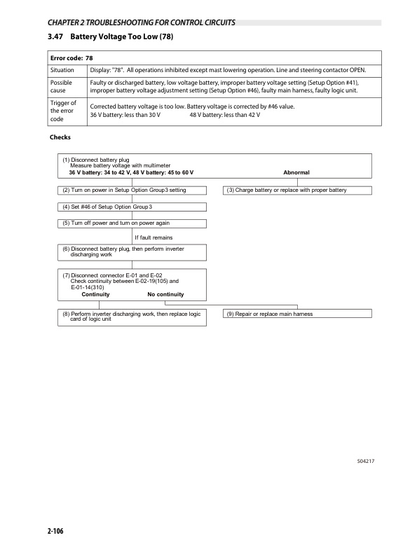
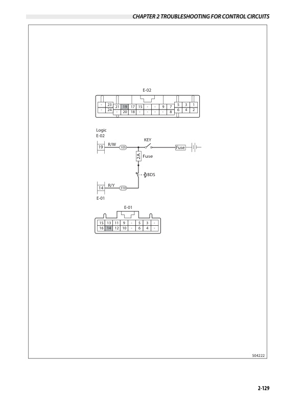
- 3.3.47. Battery Voltage Too Low (78)
- 3.3.48. Battery Voltage Too High (79)
- 3.3.49. Battery Consumption Too Much (Lo)
- 3.3.50. Tilt Angle Sensor Fault (80)
- 3.3.51. Load Sensor Fault (81)
- 3.3.52. Handle Sensor Fault (82)
- 3.3.53. PS Motor Current Sensor Fault (A4)
- 3.3.54. PS Motor Over-current (A5)
- 3.3.55. PS Handle Brake Fault (A7)
- 3.3.56. Battery Side Way Exchange Interlock (A8)
- 3.3.57. Parking brake warning (A9)
- 3.3.58. Battery Consumption Much
- 3.3.59. Brake Oil, Low Level
- 3.3.60. RTC Battery Low
- 4. Chapter 3 MOTOR
- 4.1. Motor Installation Positions
- 4.2. Specifications
- 4.3. Structures
- 4.3.1. Traction motor
- 4.3.2. Pump motor
- 4.3.3. EPS motor
- 4.4. Removing Transfer Assemblies, Traction Motors
- 4.5. Disassembling Traction motor
- 4.5.1. Disassembly Sequence
- 4.6. Inspecting Traction Motor
- 4.6.1. Inspecting Rotor
- 4.6.2. Inspecting Motor
- 4.6.3. Inspection of insulation
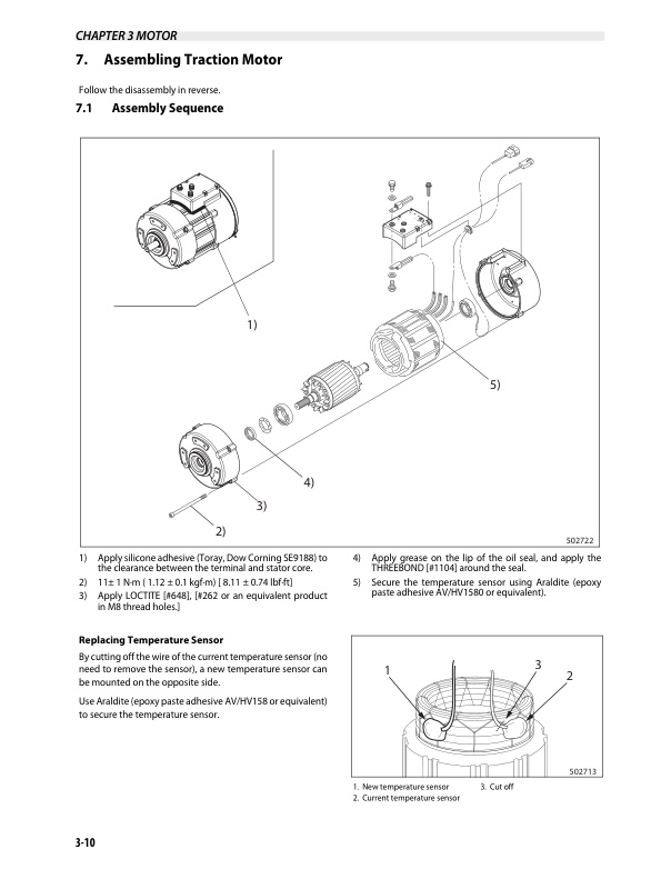
- 4.7. Assembling Traction Motor
- 4.7.1. Assembly Sequence
- 4.8. Removing Pump Motor
- 4.8.1. Suggestions for Removal
- 4.9. Disassembing Pump Motor
- 4.9.1. Disassembly Sequence
- 4.10. Inspecting Pump Motor
- 4.10.1. Inspecting Rotor
- 4.10.2. Inspecting Motor
- 4.10.3. Inspection of insulation
- 4.11. Assembling Pump motor
- 4.11.1. Assembly Sequence
- 4.12. Tightening of High-power Cable Terminals
- 4.13. Removing EPS Motor
- 4.13.1. Suggestions for Removal
- 4.14. Disassembling EPS Motor
- 4.15. Inspecting EPS Motor
- 4.15.1. Inspecting Armature
- 4.15.2. Inspecting Motor
- 4.15.3. Inspecting Oil Seal and Permanent Magnet
- 4.16. Inspecting EPS Motor
- 4.16.1. Brush
- 4.17. Troubleshooting
- 5. Chapter 4 HOW TO READ CIRCUIT DIAGRAMS
- 5.1. Description of Circuit Diagrams
- 5.1.1. Schematic Diagram
- 5.1.2. Connector Diagrams
- 5.2. How to Read Circuit Diagrams
- 5.2.1. Symbols
- 5.2.2. Sheet Symbol
- 5.2.3. Connecting Lines
- 5.2.4. Equipment
- 5.2.5. Relay Contactor and Coil
- 5.2.6. Connectors
- 5.2.7. Indication of Connecting Line
- 5.2.8. Indication of GND (Earth)
- 5.2.9. Indication of Another Specification
- 5.3. How to Read Connector Diagrams
- 6. Chapter 5 CIRCUIT DIAGRAM
Related products
-
Mitsubishi FB16NT, FB18NT, FB20NT Chassis, Mast and Options Service Manual 99719-78100
$50.00 Add to cart -
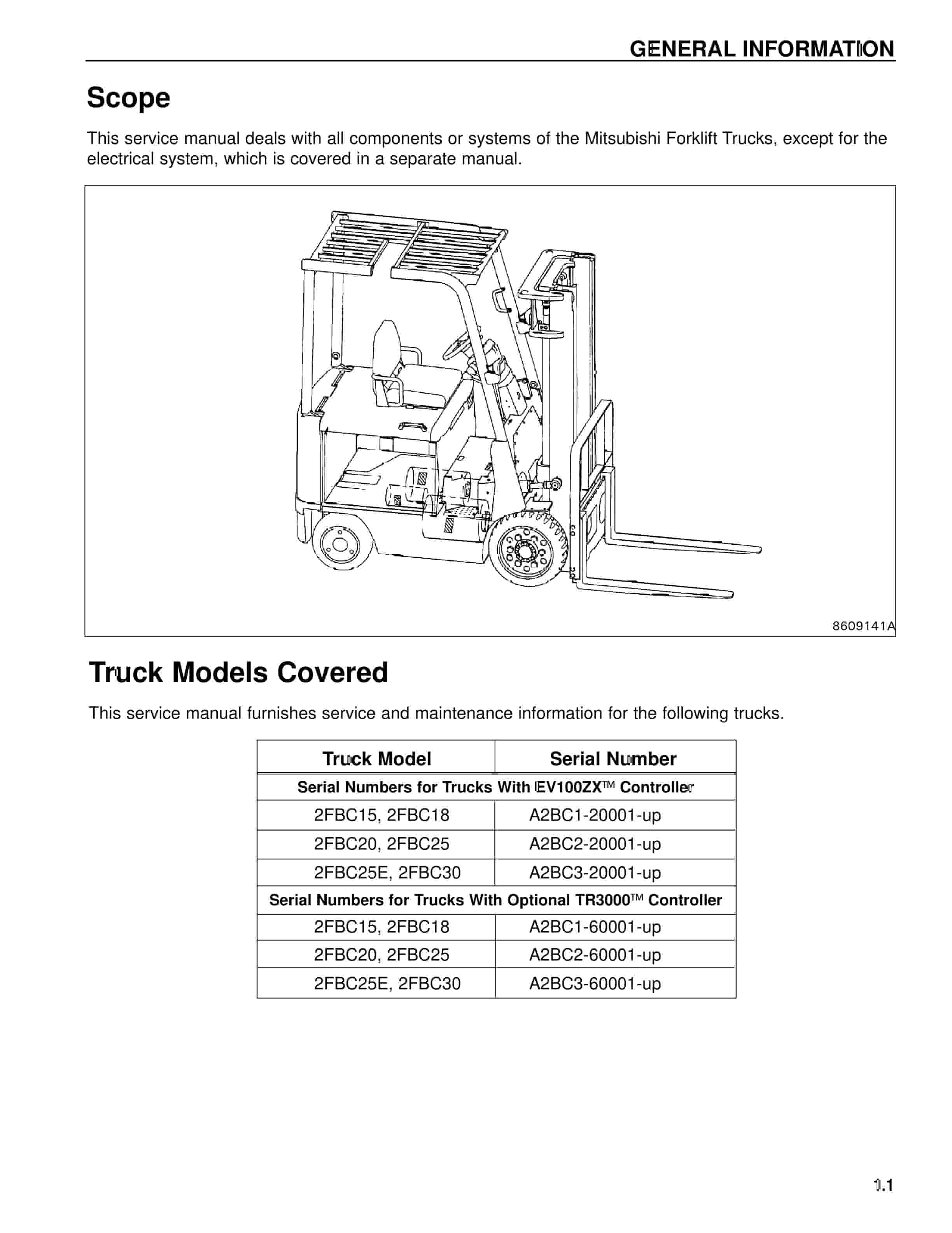
Mitsubishi 2FBC25 Forklift Service Manual
$50.00 Add to cart -
Mitsubishi 1204E Diesel Engine Service Manual SMEEA-AF15E-200
$50.00 Add to cart -
Mitsubishi 4DQ5, S4E, S4E2 Diesel Engine Service Manual
$50.00 Add to cart -
Mitsubishi 4G63, 4G64 Gasoline Engine Service Manual 99729-74120
$50.00 Add to cart


