

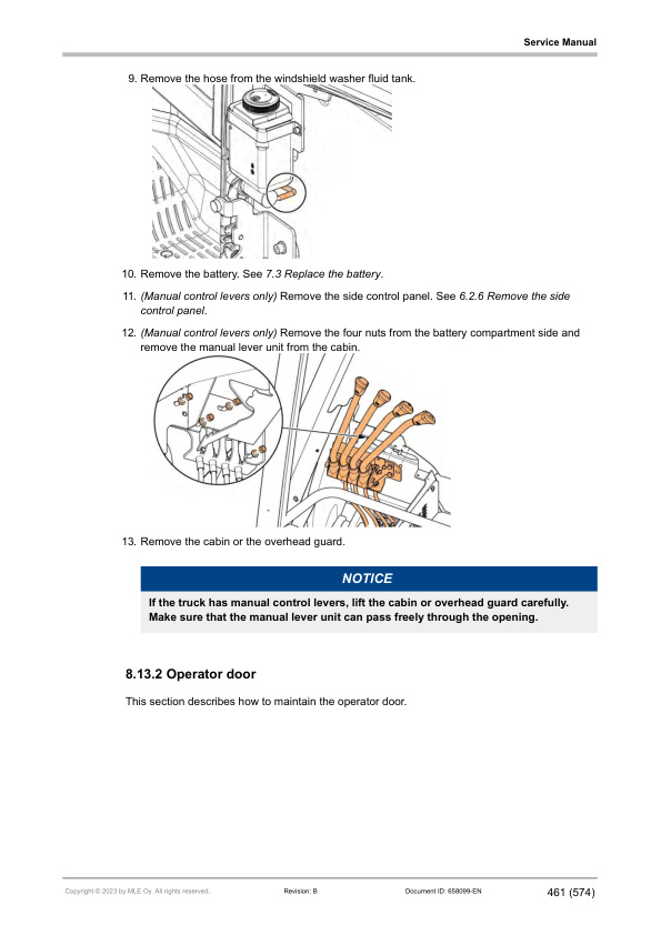
Mitsubishi FB40N, FB45N, FB50CN, FB50N, FB50NH, FB55NH Service Manual 658099 EN B
$50.00
- Type Of Manual: Service Manual
- Manual ID: 658099
- Language: EN B
- Number of Pages: 576
- Size: 16.1MB
- Format: PDF
Product details
-
Model List:
- FB40N, FB45N, FB50CN, FB50N, FB50NH, FB55NH
- 1. Table of contents
- 2. Foreword
- 3. How to read this manual
- 3.1. Safety-related signs
- 3.2. Safety symbols
- 3.3. Units
- 3.4. Interactive links
- 4. Safety instructions
- 4.1. General safety instructions
- 4.2. Safety requirements for industrial trucks
- 4.3. Repairs and structural modifications
- 4.4. Seat belt
- 4.5. Wheels
- 4.6. LOCKOUT and TAGOUT
- 4.7. Service area safety
- 4.8. Personal safety
- 4.9. Work safety
- 4.10. Operating temperature
- 5. General information
- 5.1. Truck models covered by this manual
- 5.2. Identification plates and decals
- 5.3. Special tools
- 5.4. Operating position
- 5.5. Operating direction
- 5.6. Transportation
- 5.6.1. Lifting the truck
- 5.6.2. Towing connection
- 5.6.3. Towing the truck
- 5.6.4. Brake release
- 5.7. Assembly and commissioning
- 5.8. Order spare parts
- 6. Main components
- 6.1. Truck covers
- 6.2. Overhead guard
- 6.3. Cabin
- 6.3.1. Manual holder
- 6.3.2. Emergency exits
- 6.4. Operators seat
- 6.5. Operating devices
- 6.5.1. Steering wheel
- 6.5.2. Mini steering wheel
- 6.5.3. Armrest
- 6.5.4. Manual levers
- 6.5.5. Side control panel
- 6.6. Display panel
- 6.6.1. Emergency stop button
- 6.6.2. Key switch
- 6.6.3. Display control buttons
- 6.6.4. Truck display
- 6.7. Pedals
- 6.7.1. Accelerator pedal
- 6.7.2. Brake pedal
- 6.7.3. Electronic friction lock pedal (option)
- 6.7.4. Dual pedal
- 6.7.5. Pedal functionalities
- 6.8. Battery inspection hatch
- 6.9. Electric system
- 6.9.1. Electrical operation
- 6.9.2. Controllers
- 6.9.3. Vehicle master controller
- 6.9.4. Traction controller
- 6.9.5. Pump controller
- 6.9.6. Steering controller
- 6.9.7. Sensors and switches
- 6.9.8. Option panel
- 6.9.9. Fuses
- 6.9.10. Relays and contactors
- 6.9.11. DC/DC converter
- 6.9.12. Armrest connector
- 6.9.13. Display connector
- 6.9.14. Steering feedback device
- 6.10. Hydraulic operation
- 6.10.1. Hydraulic operation overview
- 6.10.2. Hydraulic operation lifting/lowering
- 6.10.3. Hydraulic symbols
- 6.10.4. Hydraulic valve unit with fingertip controls
- 6.10.5. Hydraulic valve unit with manual levers
- 6.10.6. Hydraulic supply system
- 6.10.7. Hydraulic flow distribution with additional hydraulic functions
- 6.11. Drive axle
- 6.12. Brakes
- 6.12.1. Service brake
- 6.12.2. Parking brake
- 6.13. Rear axle
- 6.14. Load handling
- 6.14.1. Lifting carriage
- 6.14.2. Integrated sideshift carriage
- 6.14.3. Hook-on sideshift
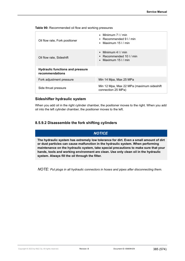
- 6.14.4. Integrated fork positioner with sideshift
- 6.14.5. Load backrest
- 6.15. Mast
- 6.15.1. Simplex mast
- 6.15.2. Triplex mast
- 6.15.3. Mast chains
- 6.15.4. Main rollers
- 6.15.5. Mast cylinders
- 6.15.6. Automated performance reduction based on lift height
- 6.16. Wheels
- 6.16.1. Solid rubber wheels
- 6.16.2. Pneumatic wheels
- 6.16.3. Cushion wheels
- 7. Maintenance
- 7.1. Maintenance intervals
- 7.2. Truck covers
- 7.2.1. Remove the pedal plate
- 7.2.2. Open the battery door
- 7.2.3. Remove the back cover
- 7.2.4. Remove the steering wheel cover
- 7.2.5. Remove the control panel
- 7.2.6. Remove the side control panel
- 7.2.7. Remove the front top side cover
- 7.2.8. Remove the air intake cover
- 7.2.9. Remove the interior panel
- 7.2.10. Remove the electric panel cover
- 7.2.11. Remove the step cover
- 7.2.12. Open the side door
- 7.2.13. Remove the right side cover
- 7.3. Cabin
- 7.3.1. Windshield washer tank
- 7.3.2. Examine the air filters of the heater
- 7.3.3. Replace the air filters of the air conditioner
- 7.3.4. Cabin seals
- 7.3.5. Air conditioner unit
- 7.4. Drive unit
- 7.4.1. Leakage check of the drive axle
- 7.4.2. Fastening of the drive axle
- 7.4.3. Lubricate the drive axle
- 7.4.4. Test the parking brake
- 7.4.5. Maintenance of the parking brake and the service brake
- 7.4.6. Test the regenerative brake
- 7.5. Hydraulics
- 7.5.1. Hydraulic system maintenance
- 7.5.2. Leakage check of the hydraulic system
- 7.5.3. Replace the hydraulic oil return filter
- 7.5.4. Replace the air breather filter
- 7.5.5. Cleaning of the hydraulic oil suction filter
- 7.5.6. Oil level
- 7.5.7. Operation of the hydraulics
- 7.5.8. Relief valves
- 7.5.9. Hydraulic oil change
- 7.5.10. Hoses and cylinders
- 7.5.11. Lubricate the pump axle splines
- 7.5.12. Lubricate the steering unit pump axle splines
- 7.5.13. Clean the oil tank
- 7.6. Mast
- 7.6.1. Mounting of the mast
- 7.6.2. Wear level of the mast rollers and contact surfaces
- 7.6.3. Chain tension
- 7.6.4. Chain lubrication
- 7.6.5. Chain wear measurement
- 7.6.6. Check the chain anchors and locking pins
- 7.6.7. Check the cylinders and piston rods
- 7.6.8. Lifting and lowering speed
- 7.6.9. Lubrication of the mast channel surfaces
- 7.6.10. Lifting test
- 7.6.11. Examine the welding in the mast for cracks
- 7.6.12. Mounting of any attachments and load-carrying components
- 7.6.13. Examine the welding of the cylinders and masts for cracking
- 7.6.14. Examine the rollers, pins and welds for cracking and damage
- 7.6.15. Apply grease to the lubrication points of the tilt cylinder
- 7.6.16. Additional mast attachments
- 7.7. Lifting carriage
- 7.7.1. Examine the welding in lifting carriage for cracks
- 7.7.2. Examine the load backrest for cracks
- 7.7.3. Fork inspection
- 7.7.4. Maintenance of the integrated sideshift carriage
- 7.7.5. Maintenance of the integrated fork positioner with sideshift
- 7.8. Rear axle
- 7.8.1. Lubricate the rear axle
- 7.8.2. Examine the operating condition of the bearings, check for looseness of the bearings
- 7.8.3. Examine the welds for cracks
- 7.8.4. Examine the mounting of the rear axle
- 7.8.5. Examine the condition of the rubber spring
- 7.9. Wheels
- 7.9.1. Damage and wear in the wheels
- 7.9.2. Before you replace the wheels
- 7.9.3. Front wheels
- 7.9.4. Rear wheels
- 7.10. Electrics
- 7.10.1. Test the functionality of sensors
- 7.10.2. Steering wheel functions
- 7.10.3. Horn
- 7.10.4. Electrical connections tightening torques
- 7.10.5. Cables and wiring
- 7.10.6. Examine and clear the alarm history
- 7.10.7. Insulation resistance test
- 7.10.8. Discharge the controllers
- 7.10.9. Emergency stop button functionality check
- 7.10.10. Key switch functionality check
- 7.10.11. Replace the filter of the air intake
- 7.11. Safety
- 7.11.1. Inspect the seat belt
- 7.12. General
- 7.12.1. How to clean the truck
- 7.12.2. Lubrication
- 7.12.3. Examine the welding in the truck frame for cracking
- 7.12.4. Examine the truck frame and the lifting carriage
- 7.12.5. Examine the overhead guard for deformation, cracking and damage
- 7.12.6. Examine the gas springs
- 7.12.7. Examine the condition and position of the identification plates
- 7.12.8. Examine the covers
- 7.12.9. Safety functions
- 7.12.10. Examine the fastening of the steering wheel
- 8. Battery maintenance
- 8.1. Lead-acid batteries
- 8.1.1. Safety with lead-acid batteries
- 8.1.2. General information
- 8.1.3. Requirements for battery charging areas
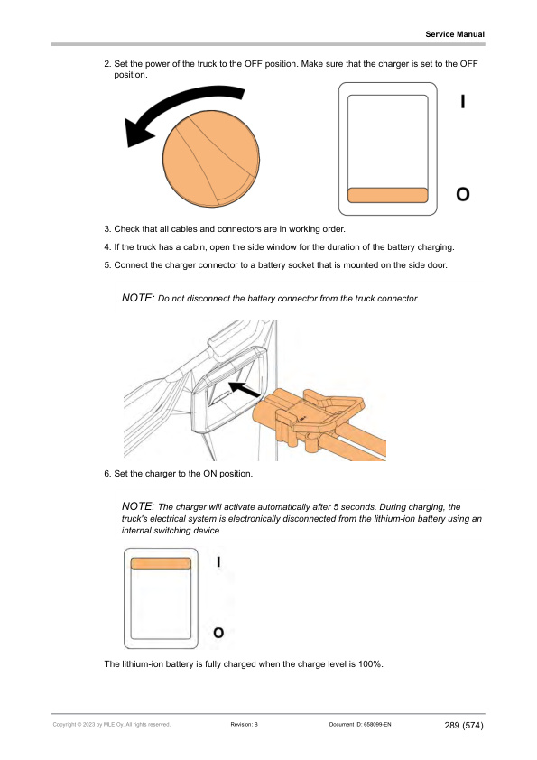
- 8.1.4. Charge the battery
- 8.1.5. Charge the battery with easy charging
- 8.1.6. Battery maintenance
- 8.1.7. Malfunctions
- 8.1.8. Acquire a new battery
- 8.1.9. Storage
- 8.2. Lithium-ion batteries
- 8.2.1. General information
- 8.2.2. Safety signs
- 8.2.3. Requirements for battery charging areas
- 8.2.4. Charge the battery
- 8.2.5. Battery maintenance
- 8.2.6. Acquire a new battery
- 8.2.7. Storage
- 8.3. Replace the battery
- 8.3.1. General safety instructions
- 8.3.2. Replace the battery with a lifting device
- 8.3.3. Remove the battery with the battery sideway exchange tools
- 8.3.4. Install a battery with the battery sideway exchange tools
- 9. Repair
- 9.1. Repair drive unit
- 9.1.1. Drive axle lifting and handling
- 9.1.2. Remove the drive axle
- 9.1.3. Remove the motor and cover of the drive axle
- 9.1.4. Replace the brake discs
- 9.1.5. Replace the hub and main seal
- 9.1.6. Install the motor and cover of the drive axle
- 9.1.7. Install the drive axle
- 9.1.8. Bleed the service brake
- 9.2. Repair rear axle
- 9.2.1. Remove the rear axle
- 9.3. Repair hydraulic system
- 9.3.1. Remove the pump motor
- 9.3.2. Disassemble the steering unit
- 9.3.3. Set the lifting pressure
- 9.3.4. Disassemble the coils
- 9.3.5. Disassemble the M1, M2 and M9 valves
- 9.3.6. Remove the clamp release valve
- 9.4. Repair mast
- 9.4.1. Using the mast bearing tool
- 9.4.2. Remove the mast
- 9.4.3. Disassemble the mast
- 9.4.4. Repair mast chains
- 9.4.5. Repair free lift cylinder
- 9.4.6. Repair side cylinders
- 9.4.7. Repair tilt cylinders
- 9.4.8. Replace the main rollers of the mast
- 9.5. Repair lifting carriage
- 9.5.1. Remove the lifting carriage
- 9.5.2. Adjust the rollers of the lifting carriage
- 9.5.3. Replace the guidance rollers of the lifting carriage
- 9.5.4. Replace the main rollers of the lifting carriage
- 9.5.5. Replace the load backrest
- 9.5.6. Repair integrated sideshift carriage
- 9.5.7. Repair hook-on sideshift carriage
- 9.5.8. Troubleshooting the fork positioner with sideshift
- 9.5.9. Repair integrated fork positioner with sideshift
- 9.5.10. Repair hook-on fork positioner with sideshift
- 9.6. Repair pedals
- 9.6.1. Remove the accelerator pedal
- 9.6.2. Remove the brake pedal
- 9.6.3. Disassemble the brake pedal
- 9.6.4. Remove the electronic friction lock pedal
- 9.6.5. Remove the dual pedal plate
- 9.6.6. Remove the dual pedal
- 9.6.7. Adjust the dual pedal
- 9.6.8. Adjust the direction sensor of the dual pedal
- 9.6.9. Adjust the dual pedal angle sensor
- 9.7. Repair steering wheel
- 9.7.1. Remove the steering wheel unit
- 9.7.2. Remove the steering wheel gas spring
- 9.7.3. Remove the lever unit
- 9.7.4. Remove the levers
- 9.8. Repair mini steering wheel
- 9.8.1. Disassemble the mini steering wheel
- 9.8.2. Disassemble the mini steering wheel holder
- 9.9. Repair armrest
- 9.9.1. Remove the armrest
- 9.9.2. Remove the armrest base plate
- 9.9.3. Replace the armrest padding
- 9.9.4. Fingertip control armrest
- 9.9.5. Dual joystick armrest
- 9.9.6. Calibrate the armrest
- 9.10. Repair operators seat
- 9.10.1. Remove the operators seat from the truck
- 9.10.2. Replace the seat padding
- 9.10.3. Replace the seat belt
- 9.10.4. Replace the seat switch
- 9.10.5. Replace the gas spring
- 9.10.6. Replace the seat armrest
- 9.10.7. Adjust the height of the seat armrest
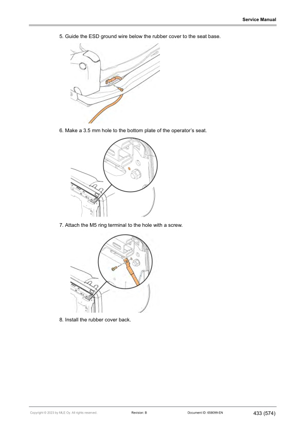
- 9.10.8. Ground the operators seat
- 9.10.9. MSG65
- 9.10.10. MSG75
- 9.11. Repair electric system
- 9.11.1. Remove the electric panel
- 9.11.2. Remove the contactor panel
- 9.11.3. Replace the horn
- 9.12. Repair sensors and switches
- 9.12.1. Replace the rotation sensor
- 9.12.2. Replace the battery door sensor
- 9.12.3. Replace the side door sensor
- 9.12.4. Replace the rear axle sensor
- 9.12.5. Replace the tilt angle sensor
- 9.12.6. Replace the mast height sensor
- 9.12.7. Replace the sensors of the hydraulic valve unit with manual levers
- 9.12.8. Replace the manual lever switches
- 9.12.9. Replace the steering wheel sensor
- 9.12.10. Replace the mini steering wheel sensors
- 9.12.11. Replace the pressure sensor
- 9.12.12. Replace the parking brake sensor
- 9.12.13. Replace the horn switch
- 9.12.14. Replace the side control panel switches
- 9.12.15. Replace the autolight sensor
- 9.13. Repair cabin
- 9.13.1. Remove the cabin or the overhead guard
- 9.13.2. Operator door
- 9.13.3. Rear window
- 9.13.4. Manual holder
- 9.13.5. Windshield washer (cabin truck)
- 9.13.6. Sun guard
- 9.13.7. Reading light
- 9.13.8. Cabin fan
- 9.13.9. Heater
- 9.13.10. HVAC
- 9.14. Replace the gas spring of the battery door
- 10. TruckTool Diagnostics
- 10.1. Overview
- 10.2. Location of the service socket
- 11. Parameter descriptions
- 12. Service data
- 12.1. Special tightening torques
- 12.2. Tightening torques for standard bolts and nuts
- 12.3. Oils and lubricants
- 12.3.1. Lubrication points
- 12.3.2. Rear axle
- 12.3.3. Mast chains
- 12.3.4. Mast channels
- 12.3.5. Pump axle splines
- 12.4. Air conditioner
- 12.5. Troubleshooting
- 12.5.1. Troubleshooting case examples
- 12.5.2. Traction
- 12.5.3. Brakes
- 12.5.4. Hydraulics
- 12.5.5. Steering
- 12.5.6. Charging
- 13. Options
- 13.1. Options overview
- 13.2. Accessory rack
- 13.3. A4 paper holder
- 13.4. Computer holder
- 13.5. Scanner holder
- 13.6. Holder arm
- 13.7. Reverse drive handle with horn button
- 13.8. Loose mast components
- 13.9. Smart backup alarm
- 13.10. Rear combination and tail lights kit
- 13.10.1. Turn signals
- 13.10.2. Brake lights
- 13.10.3. Front lights
- 13.11. Amber strobe
Related products
-
Mitsubishi 1204E Diesel Engine Service Manual SMEEA-AF15E-200
$50.00 Add to cart -
Mitsubishi 4G33, 4G52, 4G54 Service Manual 99719-41111
$50.00 Add to cart -
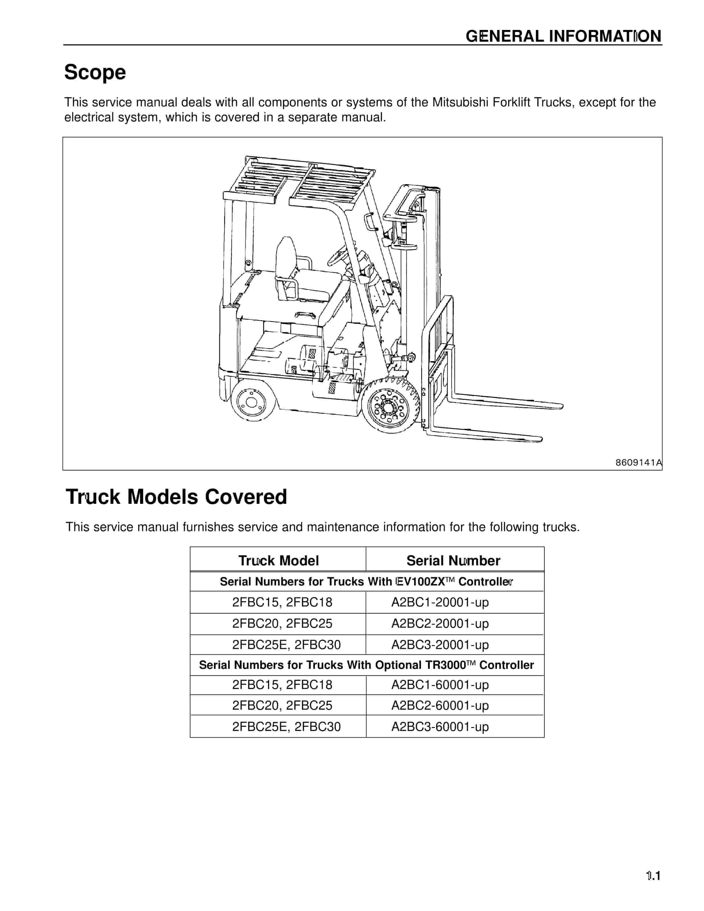
Mitsubishi 2FBC20 Forklift Service Manual
$50.00 Add to cart -
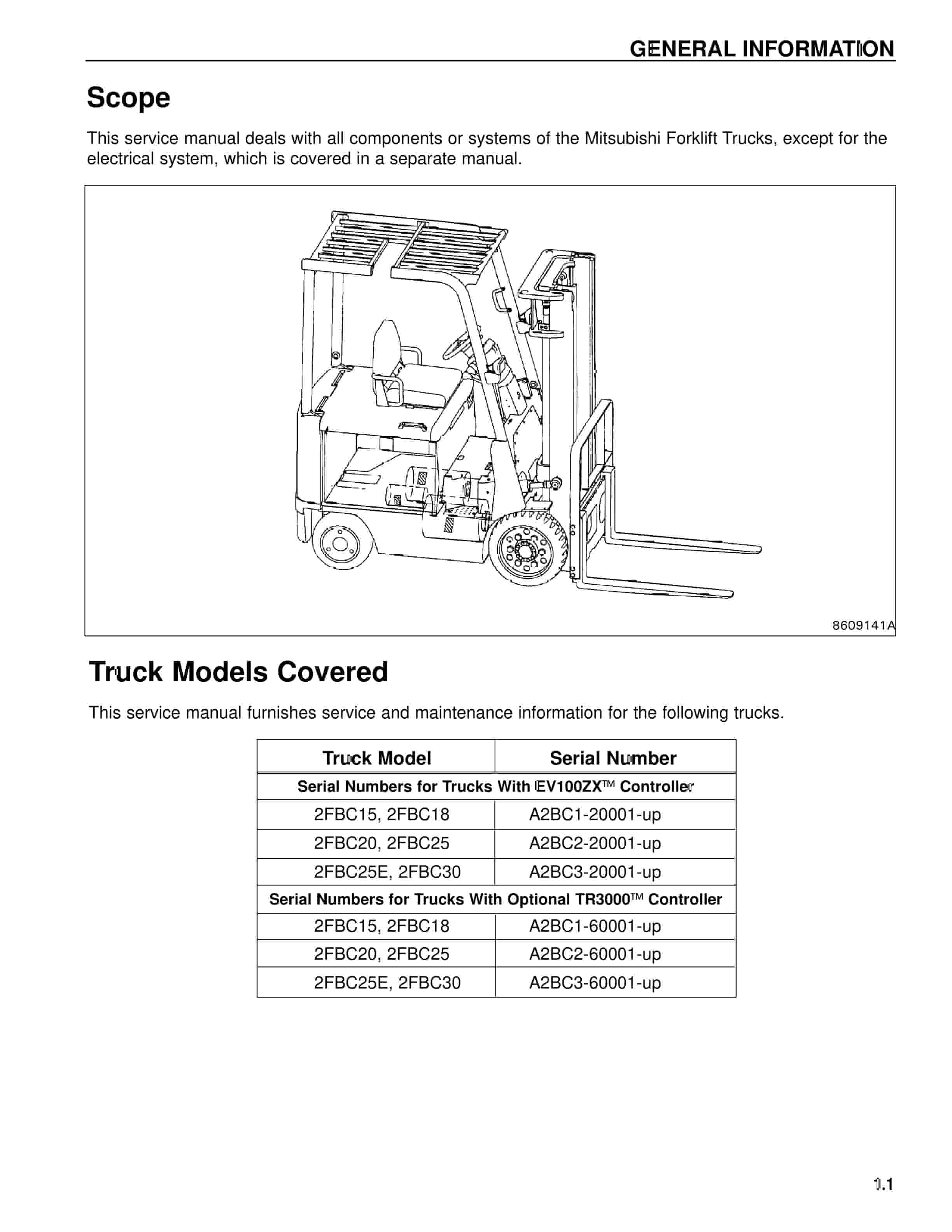
Mitsubishi 2FBC25 Forklift Service Manual
$50.00 Add to cart -
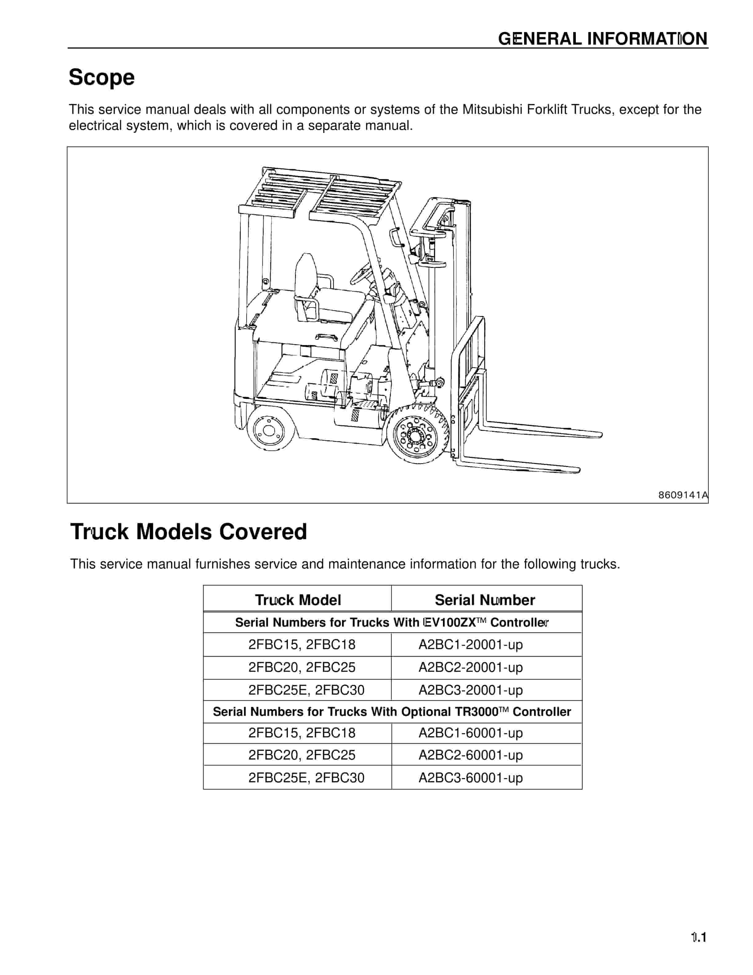
Mitsubishi 2FBC15 Forklift Service Manual
$50.00 Add to cart


