

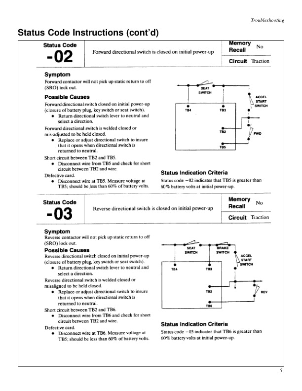
Mitsubishi FBC30, FBC35 Forklift Service Manual
$50.00
- Type Of Manual: Service Manual
- Number of Pages: 343
- Size: 7.7MB
- Format: PDF
Product details
-
Model List:
- FBC30, FBC35
- 1. FOREWARD
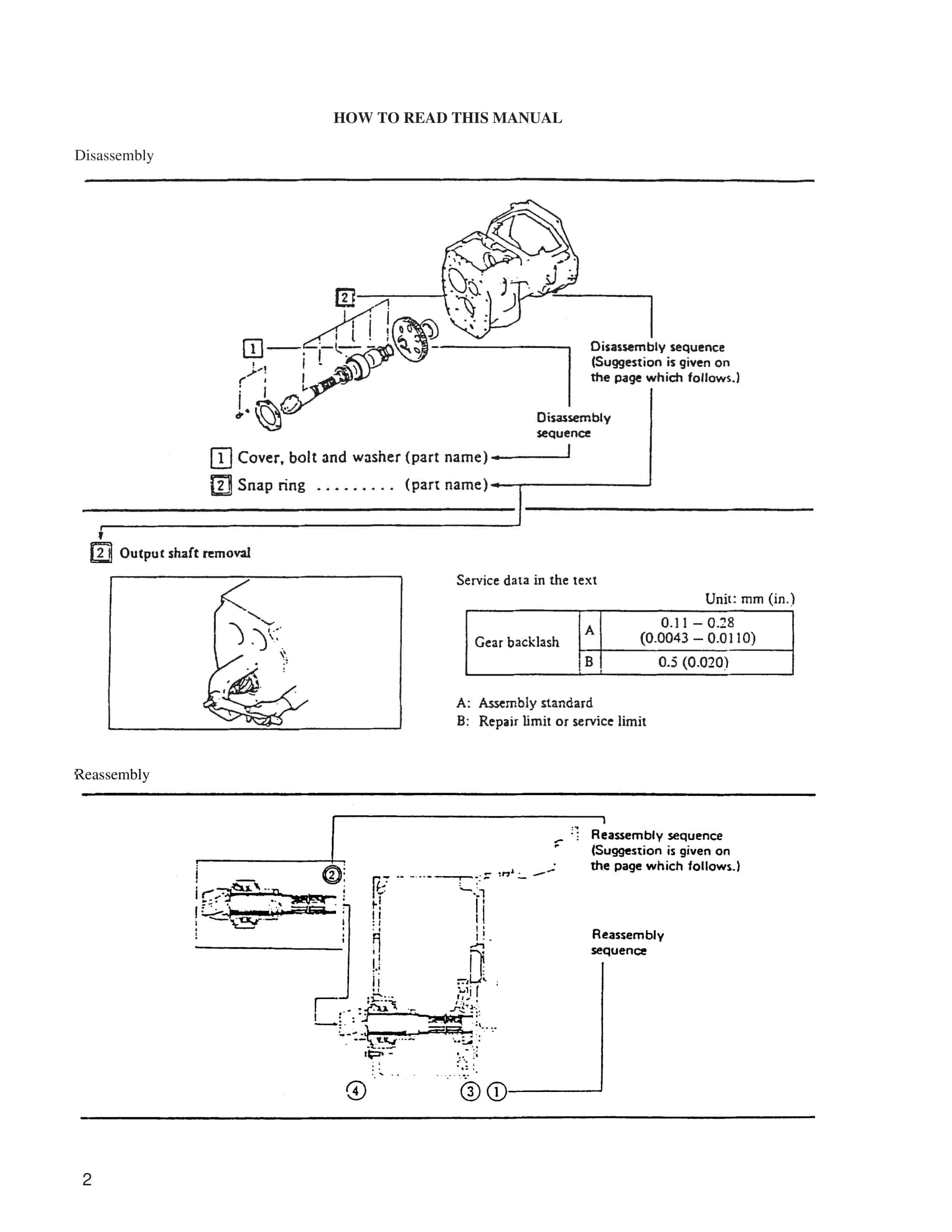
- 1.1. How To Read This Manual
- 2. GENERAL INFORMATION
- 2.1. MODEL VIEW
- 2.2. TRUCK MODELS COVERED
- 2.3. NAME PLATE AND SERIAL NUMBER LOCATIONS
- 2.4. SPECIFICATIONS
- 3. BRAKE SYSTEM
- 3.1. DESCRIPTION
- 3.1.1. Automatic adjusting device
- 3.1.2. Brake pedal and associated parts
- 3.1.3. Parking brake lever mechanism
- 3.2. DISASSEMBLY AND REASSEMBLY
- 3.2.1. Master cylinder
- 3.2.2. Wheel brakes
- 3.3. INSPECTION AND ADJUSTMENT
- 3.3.1. Automatic adjusting device
- 3.3.2. Manual adjustment
- 3.3.3. Bleeding air out of the brake fluid line
- 3.3.4. Brake test
- 4. HYDRAULIC SYSTEM
- 4.1. DESCRIPTION
- 4.1.1. Hydraulic Tank
- 4.1.2. Hydraulic Pump
- 4.1.3. Control Valve
- 4.1.4. Tilt Cylinders
- 4.2. REMOVAL AND INSTALLATION
- 4.2.1. Hydraulic Pump
- 4.2.2. Control Valve
- 4.2.3. Tilt Cylinders
- 4.3. DISASSEMBLY AND REASSEMBLY
- 4.3.1. Hydraulic Pump
- 4.3.2. Control Valve (MC)
- 4.3.3. Tilt Cylinders
- 4.4. INSPECTION AND ADJUSTMENT
- 4.4.1. Hydraulic Tank
- 4.4.2. Hydraulic Pump
- 4.4.3. Control Valve
- 5. INSPECTION GUIDE
- 5.1. PREFACE TO INSPECTION GUIDE
- 5.2. INSPECTION GUIDE
- 6. MAST AND FORKS
- 6.1. MAST MODEL DESIGNATION
- 6.1.1. Mast Model Number Location
- 6.1.2. Mast Model Number Coding
- 6.1.3. Mast Types
- 6.2. DESCRIPTION
- 6.2.1. Dual-stage panoramic mast
- 6.2.2. Dual-stage full free-lift panoramic mast
- 6.2.3. Triple-stage full free-lift panoramic mast
- 6.2.4. Hook device
- 6.2.5. Lift Cylinders
- 6.2.6. Flow regulator valve
- 6.2.7. Down safety valves
- 6.3. REMOVAL AND INSTALLATION
- 6.3.1. Mast and lift bracket assembly
- 6.3.2. Lift cylinders
- 6.3.3. Element mast piping
- 6.4. DISASSEMBLY AND REASSEMBLY
- 6.4.1. Dual-stage panoramic mast
- 6.4.2. Dual-stage full free-lift panoramic mast
- 6.4.3. Triple-stage full free-lift panoramic mast
- 6.4.4. Lift Cylinders
- 6.4.5. Flow regulator valve
- 6.4.6. Down safety valves
- 6.5. INSPECTION AND ADJUSTMENT
- 6.5.1. Lift chains, chain wheels and chain wheel supports
- 6.5.2. Lift chain tension
- 6.5.3. Longitudinal clearance adjustment on mast and lift bracket rollers
- 6.5.4. Mast strip adjustment
- 6.5.5. Lateral clearance adjustment on outer mast and inner mast rollers
- 6.5.6. Lateral clearance adjustment on outer mast and middle mast rollers
- 6.5.7. Lateral clearance adjustment on middle mast and inner mast rollers
- 6.5.8. Lateral clearance adjustment on lift bracket rollers
- 6.5.9. Mast cushion deflection inspection
- 6.5.10. Lift cylinder stroke adjustment
- 6.5.11. Hook device inspection
- 6.5.12. Pulley hose inspection
- 6.5.13. Flow regulator valve adjustment
- 6.5.14. Testing
- 7. REAR AXLE
- 7.1. DESCRIPTION
- 7.2. REMOVAL AND INSTALLATION
- 7.2.1. Rear Tires and Rear Axle
- 7.3. DISASSEMBLY AND REASSEMBLY
- 7.3.1. Disassembly
- 7.3.2. Reassembly
- 7.4. INSPECTION AND ADJUSTMENT
- 7.4.1. Toe-in adjustment
- 7.4.2. Minimum Turning Radius Adjustment
- 8. REDUCTION DIFFERENTIAL AND FRONT AXLE
- 8.1. DESCRIPTION
- 8.2. REMOVAL AND INSTALLATION
- 8.2.1. Front tires
- 8.3. DISASSEMBLY AND REASSEMBLY
- 8.3.1. Front axle
- 8.3.2. Reduction gear and differential
- 8.4. INSPECTION AND ADJUSTMENT
- 8.4.1. Side bearing preload and adjustment
- 8.4.2. Reduction gear backlash adjustment
- 8.4.3. Face runout measurement
- 8.4.4. Tooth contact adjustment
- 8.5. TRANSFER CASE
- 8.5.1. Disassembly
- 8.5.2. Reassembly
- 9. SERVICE DATA
- 9.1. MAINTENANCE STANDARDS
- 9.1.1. Reduction differential and front axle
- 9.1.2. Rear axle
- 9.1.3. Brake system
- 9.1.4. Steering system
- 9.1.5. Hydraulic system
- 9.1.6. Masts and forks
- 9.2. TIGHTENING TORQUE CHART
- 9.3. MAINTENANCE SCHEDULE
- 9.4. PERIODICAL REPLACEMENT PARTS
- 9.5. LUBRICATION CHART
- 9.6. FUEL AND LUBRICANT SPECIFICATIONS
- 9.7. RECOMMENDED BRANDS OF LUBRICANTS
- 9.8. WEIGHT OF MAJOR COMPONENTS
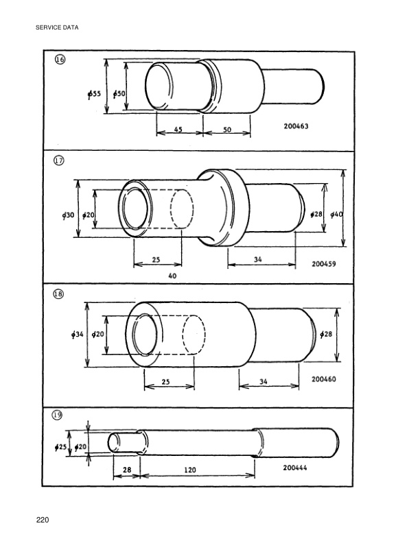
- 9.9. SPECIAL SERVICE TOOLS
- 10. STEERING SYSTEM
- 10.1. DESCRIPTION
- 10.1.1. Removal of steering pump/motor removal assembly
- 10.1.2. Steer pump disassembly
- 10.1.3. Steer pump reassembly
- 10.2. REMOVAL AND INSTALLATION
- 10.2.1. Steering gear and power cylinder
- 10.3. DISASSEMBLY AND REASSEMBLY
- 10.3.1. Steering gear
- 10.3.2. Power cylinder
- 10.4. INSPECTION AND ADJUSTMENT
- 10.4.1. Steering wheel free play
- 10.4.2. Steering effort
- 10.5. HYDRAULIC PRESSURE MEASUREMENT AND ADJUSTMENT
- 11. TROUBLESHOOTING
- 11.1. TRANSFER GEAR, REDUCTION DIFFERENTIAL AND FRONT AXLE
- 11.2. REAR AXLE
- 11.3. BRAKE SYSTEM
- 11.4. STEERING SYSTEM
- 11.5. HYDRAULIC SYSTEM
- 11.6. MASTS AND FORKS
- 12. COMPONENT ASSEMBLY AND ADJUSTMENT
- 12.1. Component Location
- 12.2. Dashboard and Seat
- 12.3. Console Box Assembly
- 12.4. Combination Meter Assembly
- 12.5. Controller Compartment
- 12.5.1. Contractors-RB (Regenerative Braking), 1A, FW (Field Weakening), PS (Power Steering) and Pump (Hydraulic)
- 12.5.2. Contractor – FR (Forward/Reverse)
- 12.5.3. EV100 LX Traction Logic Card and Hydraulic Logic Card Checks and Adjustments
- 12.5.4. EV100 LX Handset
- 12.5.5. Brake Bracket
- 12.5.6. Pump Contactor Hydraulic Control Adjustment-Lift Switch
- 12.5.7. SCR Hydraulic Control Adjustment
- 13. DESCRIPTION OF LIFT TRUCK CIRCUIT
- 13.1. EV100 LX Control Panel
- 13.1.1. Control Panel Layout
- 13.1.2. Component Identification
- 13.1.3. Test Points
- 13.1.4. Logic Switch Sequence
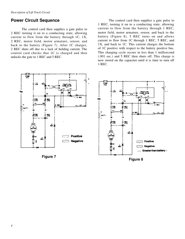
- 13.1.5. Power Circuit Sequence
- 13.1.6. Traction Control Logic Flow Chart
- 13.1.7. Control Features
- 13.2. Console
- 13.2.1. Hour Meter
- 13.2.2. Fault Indicator
- 13.2.3. Battery Discharge Indicator (BDI)
- 13.2.4. Brake Fluid Level Warning Circuit
- 13.2.5. Motor Protection Circuits
- 13.3. Horn Circuit
- 13.4. Options
- 13.4.1. Optional Backup Alarm
- 13.4.2. Optional Warning Light or Strobe
- 13.4.3. Optional Head Lamps, Working Lamps Tail Lamps-36/48V
- 13.4.4. Optional Head Lamps, Working Lamps Tail Lamps-12V
- 13.4.5. Optional Stop Light-36/48V
- 13.4.6. Optional Stop Light-12V
- 14. FOREWARD
- 15. GENERAL INFORMATION
- 15.1. Truck Models
- 15.2. External View
- 15.3. Name Plate and Serial Number Locations
- 15.4. Technical Data
- 15.4.1. General
- 15.4.2. Basic Dimensions
- 15.4.3. Performance
- 15.4.4. Control
- 15.4.5. Power Line
- 15.4.6. Axles Wheels
- 15.4.7. Brake System
- 15.4.8. Steering System
- 15.4.9. Steering Motor
- 15.4.10. Steering Pump
- 15.4.11. Power Steering
- 15.4.12. Hydraulic System
- 15.4.13. Hydraulic Pressure for Attachment
- 15.4.14. Battery
- 15.5. Description
- 15.6. Storage
- 15.7. Maintenance
- 15.7.1. Motor Maintenance Schedule
- 15.7.2. Bearings
- 15.7.3. Insulation
- 15.7.4. Brushes
- 15.7.5. Commutator
- 15.7.6. Mechanical
- 15.7.7. Cleaning
- 15.8. Traction, Pump and Steering Disassembly
- 15.8.1. Failure
- 15.8.2. Renewal Parts
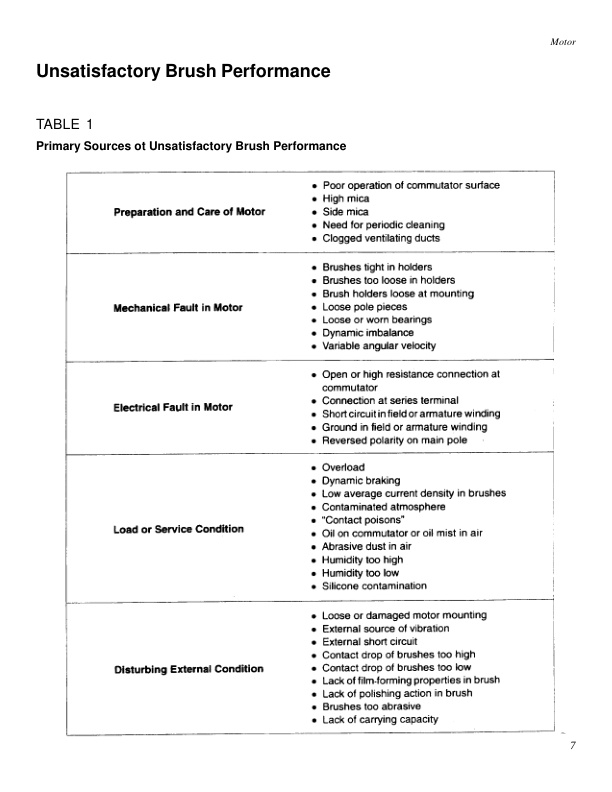
- 15.9. Unsatisfactory Brush Performance
- 15.9.1. Table 1 Primary Sources of Unsatisfactory Brush Performance
- 15.9.2. Table 2 Indications Appearing at Brushes
- 15.9.3. Table 3 Indications Appearing as Heat
- 15.9.4. Table 4 Indications Appearing at Commutator Surface
- 15.10. Commutator Check Chart
- 15.10.1. Satisfactory Commutator Surfaces
- 15.10.2. Poor Commutator Surfaces
- 15.10.3. Causes of Poor Commutator Conditions
- 16. RECOMMENDED REASSEMBLY PRACTICE
- 17. TESTING EQUIPMENT RECOMMENDATIONS
- 18. TROUBLESHOOTING
- 18.1. Introduction
- 18.2. Tools and Required Equipment
- 18.3. Frame Resistance Check
- 18.4. SCR Gerneral Maintenance
- 18.5. Status Code Descriptions
- 18.6. Status Code Instructions
- 18.7. Component Check
- 18.7.1. Control Card
- 18.7.2. Capacitor 1C
- 18.7.3. Contractors F/R (Forward/Reverse), 1A, PS (Power Steering), FW (Field Weakening), RB (Regenerative Braking) and Pump (Hydraulic
- 18.7.4. Potentiometer in Accelerator
- 18.7.5. SCRs (1 REC, REC and REC)
- 18.7.6. Rectifiers (3 REC, 4 REC, and Diode Blocks)
- 18.7.7. Thermal Protector (TP)
- 18.7.8. Filter Block (23 FIL, etc.)
- 18.7.9. Choke and Reactor T3-T4
- 18.8. Replacement of EV100 LX Components
- 18.8.1. Stud Semiconductors
- 18.8.2. Module Semiconductors
- 18.8.3. Capacitor
- 18.8.4. REC, 23 REC, and 25 REC
- 18.8.5. Filter Mounting Block
- 18.9. Secondary Troubleshooting
- 18.9.1. Table 1 Failures that Cause Reduced or No Motor Torque with SCR Control
- 18.9.2. Table 2 Failures that Cause Full or No Motor Torque with SCR Control
- 18.9.3. Table 3 Misoperation of Other Features
- 18.10. EV100 LX Hygraulic Pump Control Troubleshooting
- 18.10.1. Table 4 Failures that Cause Reduced or No Motor Torque with SCR Control
- 18.10.2. Table 5 Failures that Cause No Motor Torque with SCR Control
- 18.11. Power Cable Connections
- 18.12. Traction Control Card Wire Harness Connections
- 18.12.1. Panel Connector
- 18.12.2. TB Connections
- 18.12.3. A B Plugs
- 18.13. Hydraulic Pump SCR Control Card Wire Harness Connections
- 18.13.1. Panel Connector
- 18.13.2. TB Connections
- 18.13.3. A B Plugs
- 18.14. Traction Control Components
- 18.14.1. Potentiometer (for Accelerator)
- 18.14.2. Acclerator Switch
- 18.14.3. Brake Switch
- 18.15. Pump Driver
- 18.16. Hydraulic Control Components
- 18.16.1. Hydraulic Control Switch (Standard)
- 18.16.2. Hydraulic Control Switch (Tilt/Auxiliary)
- 18.16.3. Hydraulic Control Switch (Lift)
- 18.16.4. Potentiometer (for SCR Hydraulic Control)
- 18.17. Options
- 18.17.1. Relay for 12-Volt Stop Lamp
- 18.17.2. Volt DC/Dc Convertor
- 18.18. Console
- 18.19. EV100LX Electrical Schematic – Trucks Equipped with Contactor Hydraulics
- 18.20. EV100LX Electrical Schematic – Trucks Equipped with Optional SCR Hyrdaulics
Related products
-
Mitsubishi 4G63, 4G64 Gasoline Engine Service Manual 99729-74120
$50.00 Add to cart -
Mitsubishi 1204E Diesel Engine Troubleshooting Service Manual 99799-56104
$50.00 Add to cart -
Mitsubishi 4G33, 4G52, 4G54 Service Manual 99719-42120
$50.00 Add to cart -
Mitsubishi 4DQ5, S4E, S6E, S6E2 Service Manual 99719-52120
$50.00 Add to cart -
Mitsubishi 4G63, 4G64, 6G72 Liquefied Petroleum Gas Supplement Service Manual 99729-75100
$50.00 Add to cart


