

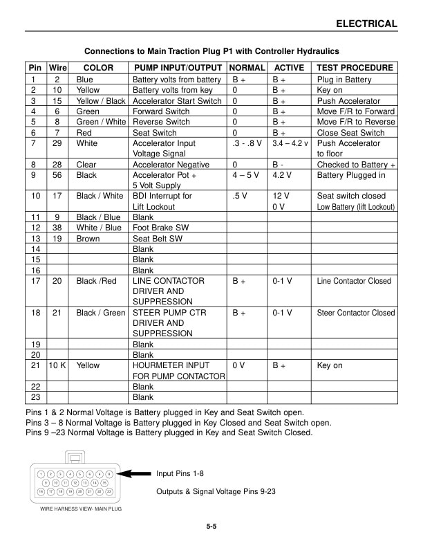
Mitsubishi FBC35N, FBC40N, FBC45N, FBC55N Chassis and Mast Service Manual WENB8472-01
$50.00
- Type Of Manual: Service Manual
- Manual ID: WENB8472-01
- Number of Pages: 365
- Size: 6.6MB
- Format: PDF
Product details
-
Model List:
- FBC35N, FBC40N, FBC45N, FBC55N
- 1. TABLE OF CONTENTS
- 2. BRAKE SYSTEM
- 2.1. BRAKE SYSTEM
- 2.1.1. Specifications
- 2.1.2. Structure
- 2.1.2.1. Brake System
- 2.1.2.2. Master Cylinder and Reservoir Tank
- 2.1.2.3. Wheel Brake
- 2.1.3. Master Cylinder
- 2.1.3.1. Disassembly
- 2.1.4. Wheel Cylinder
- 2.1.4.1. Disassembly
- 2.1.4.2. Inspection and Repair
- 2.1.4.3. Assembly
- 2.1.5. Wheel Brake
- 2.1.5.1. Disassembly
- 2.1.5.2. Inspection and Repair
- 2.1.5.3. Assembly
- 2.1.6. Parking Brake Lever
- 2.1.6.1. Inspection and Repair
- 2.1.6.2. Installation
- 2.1.7. Adjustment and Tests
- 2.1.7.1. Automatic Adjuster Test
- 2.1.7.2. Procedure for Manual Adjustment
- 2.1.7.3. Brake Fluid Line Bleeding
- 2.1.7.4. Inspecting Reservoir Tank Level Sensor
- 2.1.7.5. Procedures for Brake Pedal Adjustment
- 2.1.8. Troubleshooting
- 2.1.9. Service Data
- 3. FRONT AXLE AND REDUCTION DIFFERENTIAL
- 3.1. FRONT AXLE AND REDUCTION DIFFERENTIAL
- 3.1.1. Specifications
- 3.1.2. Structure
- 3.1.3. Procedures and Key Points for Removal and Installation
- 3.1.3.1. Front Tire
- 3.1.3.2. Front Axle Assembly
- 3.1.3.3. Reduction and Differential
- 3.1.4. Axle Shaft and Hub
- 3.1.4.1. Disassembly
- 3.1.4.2. Inspection and Repair
- 3.1.4.3. Assembly
- 3.1.4.4. Adjustments
- 3.1.5. Troubleshooting
- 3.1.6. Service Data
- 4. GENERAL INFORMATION
- 4.1. GENERAL INFORMATION
- 4.1.1. Truck Models Covered
- 4.1.2. Nameplate and Serial Number Locations
- 4.1.3. Dimensions
- 4.1.4. Dimensions Chart
- 4.1.5. General Information (Standard Models)
- 5. HYDRAULIC SYSTEM
- 5.1. HYDRAULIC SYSTEM
- 5.1.1. Hydraulic System
- 5.1.1.1. Description
- 5.1.1.1.1. Schematic
- 5.1.1.1.2. Hydraulic Tank
- 5.1.1.1.3. Hydraulic Pump
- 5.1.1.1.4. Control Valve
- 5.1.1.1.5. Lift and Tilt Cylinders
- 5.1.1.1.6. Flow Regulator Valve
- 5.1.1.1.7. Down Safety Valve
- 5.1.1.2. Removal and Installation Warning
- 5.1.2. Hydraulic Pump
- 5.1.2.1. Removal
- 5.1.2.2. Installation
- 5.1.2.3. Disassembly
- 5.1.2.3.1. Working Rules and Tips
- 5.1.2.4. Inspection after Disassembly
- 5.1.2.5. Reassembly
- 5.1.2.6. Placing Pump Back into Service
- 5.1.2.7. Inspection after Reassembly
- 5.1.2.8. Trouble Shooting
- 5.1.3. Control Valve
- 5.1.3.1. Removal
- 5.1.3.2. Installation
- 5.1.3.3. Disassembly
- 5.1.3.4. Suggestions
- 5.1.3.5. Reassembly
- 5.1.4. Lift and Tilt Cylinders
- 5.1.4.1. Removal
- 5.1.4.1.1. Lift Cylinders
- 5.1.4.1.2. Tilt Cylinders
- 5.1.4.2. Disassembly
- 5.1.4.2.1. Lift Cylinders
- 5.1.4.2.2. Tilt Cylinders
- 5.1.4.2.3. Flow Regulator Valve
- 5.1.4.3. Inspection after Disassembly
- 5.1.4.4. Precautions for Reassembly
- 5.1.5. Inspection and Adjustment
- 5.1.5.1. Hydraulic Tank
- 5.1.5.2. Control Valve
- 5.1.5.2.1. Main Relief Valve Adjustment
- 5.1.5.2.2. Auxiliary Relief Valve Adjustment
- 6. MAST AND FORKS
- 6.1. MAST AND FORKS
- 6.1.1. Specifications
- 6.1.2. Description
- 6.1.2.1. Dual-stage Panoramic Mast (Simplex Mast)
- 6.1.2.2. Triple-stage Full Free Panoramic Mast (Triplex Mast)
- 6.1.3. Disassembly and Reassembly
- 6.1.4. Dual-stage Panoramic Mast (Simplex Mast)
- 6.1.4.1. Dual-stage Full Free Panoramic Mast (Duplex Mast)
- 6.1.5. Triple-stage Full Free Panoramic Mast (Triplex Mast)
- 6.1.6. Inspection and Adjustment
- 6.1.6.1. Chain, Chain Wheel Support and Chain Wheel
- 6.1.6.2. Chain Tension Adjustment
- 6.1.6.3. Clearance Adjustment on Lift Bracket
- 6.1.6.4. Mast Clearance Adjustment
- 6.1.6.5. Main Roller Shim Replacement (Simplex Mast)
- 6.1.7. Mast Strip Adjustment
- 6.1.7.1. Tilt Angle Adjustment
- 6.1.7.2. Lift Cylinder Stroke Adjustment
- 6.1.8. Troubleshooting
- 6.1.9. Service Data
- 7. REAR AXLE
- 7.1. REAR AXLE
- 7.1.1. Specifications
- 7.1.1.1. Structure
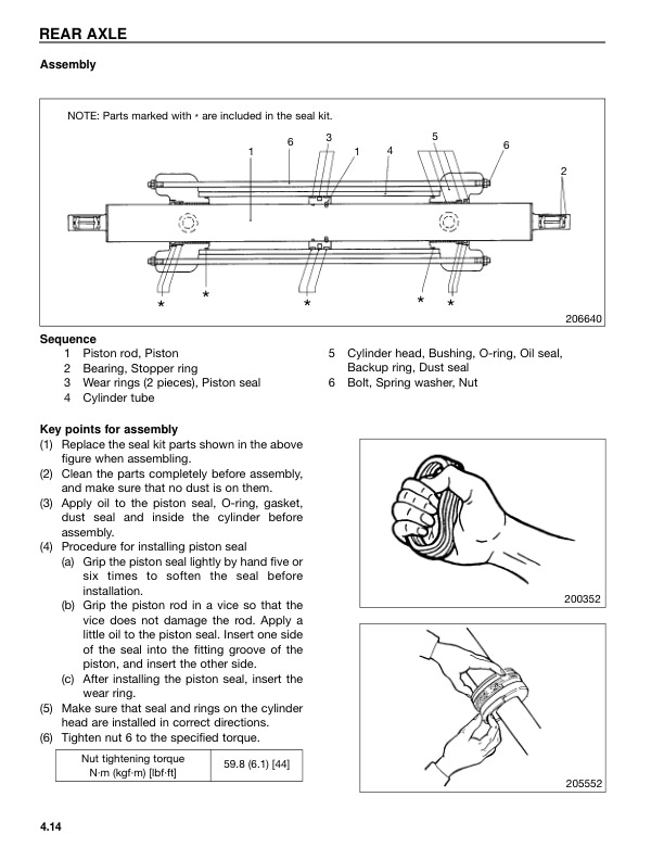
- 7.1.1.2. Rear Axle
- 7.1.1.3. Steering Cylinder
- 7.1.2. Procedures and Key Points for Removal and Installation
- 7.1.2.1. Rear Tires
- 7.1.2.2. Rear Axle
- 7.1.3. Rear Axle Assembly
- 7.1.3.1. Disassembly
- 7.1.3.2. Assembly
- 7.1.4. Steering Cylinder
- 7.1.4.1. Disassembly
- 7.1.4.2. Inspection and Repair
- 7.1.4.3. Assembly
- 7.1.5. Adjustment
- 7.1.5.1. Adjustment of Minimum Turning Radius
- 7.1.6. Troubleshooting
- 7.1.7. Service Data
- 8. SERVICE DATA
- 8.1. SERVICE DATA
- 8.1.1. Tightening Torques for Standard Bolts and Nuts
- 8.1.1.1. Fine Thread with Spring Washer
- 8.1.1.2. Fine Thread without Spring Washer
- 8.1.1.3. Course Thread with Spring Washer
- 8.1.1.4. Course Thread without Spring Washer
- 8.1.2. Maintenance Chart
- 8.1.3. Periodic Replacement Parts
- 8.1.4. Lubrication Chart
- 8.1.5. Fuel and Lubricant Specifications
- 8.1.6. Weight of Major Components
- 8.1.7. Special Service Tools
- 8.1.7.1. Special Tool Illustrations
- 8.1.8. Inspection Guide
- 9. STEERING SYSTEM
- 9.1. STEERING SYSTEM
- 9.1.1. Steering System
- 9.1.1.1. Description
- 9.1.1.1.1. Steering System
- 9.1.1.1.2. Oil Flow Sequence
- 9.1.1.1.3. General Information
- 9.1.2. Steering Gear
- 9.1.2.1. Removal
- 9.1.2.2. Installation
- 9.1.2.3. Steering Gear
- 9.1.2.4. Inspection after Removal
- 9.1.2.5. Disassembly
- 9.1.2.5.1. Working Rules and Tips
- 9.1.2.5.2. Suggestions
- 9.1.2.5.3. Inspection after Disassembly
- 9.1.2.6. Reassembly
- 9.1.2.7. Suggestions
- 9.1.3. Steer Pump
- 9.1.3.1. Removal
- 9.1.3.2. Installation
- 10. TRANSFER ASSEMBLY
- 10.1. TRANSFER ASSEMBLY
- 10.1.1. Structure and Functions
- 10.1.2. Disassembly and Reassembly
- 10.1.2.1. Disassembly
- 10.1.2.2. Inspection after Disassembly
- 10.1.2.3. Reassembly
- 10.1.3. Tightening Torque
- 11. CHECKS AND REPAIRS
- 11.1. CHECKS REPAIRS
- 11.1.1. General Information
- 11.1.2. Exploded View of Contactor
- 11.1.3. Contactor Repair
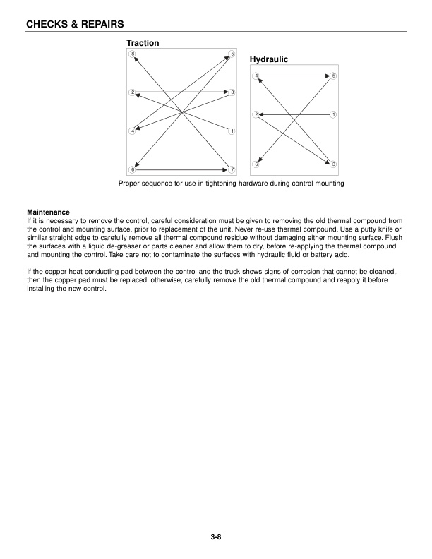
- 11.1.4. Thermal Transfer
- 11.1.5. Traction Control
- 11.1.6. Trouble Shooting Tips (Motors)
- 11.1.7. Unsatisfactory Brush Performance
- 11.1.8. Commutator Surfaces Conditions
- 12. DIAGNOSTIC STATUS CODES
- 12.1. DIAGNOSTIC STATUS CODES
- 12.1.1. Basic Checks
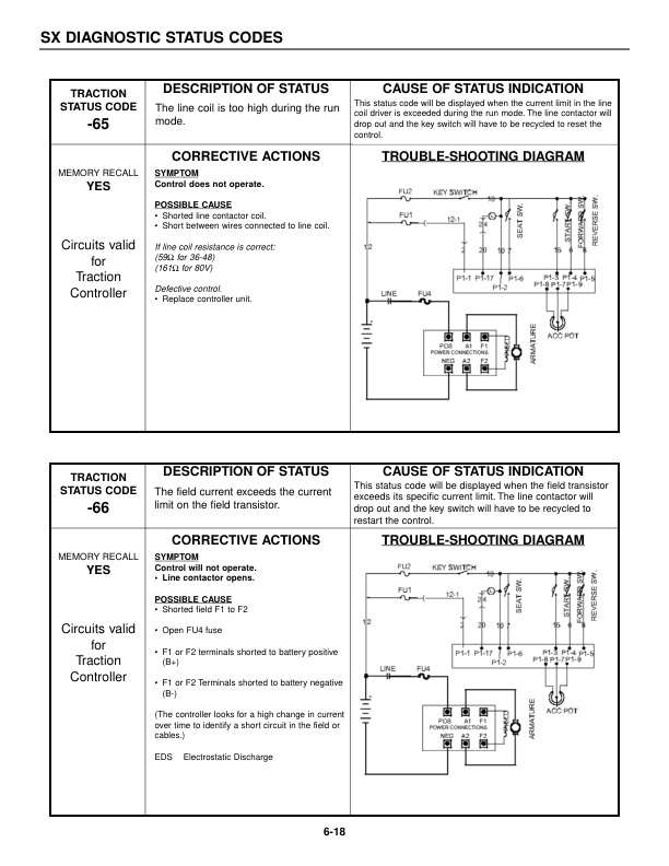
- 12.1.2. Status Codes
- 13. ELECTRICAL
- 13.1. ELECTRICAL
- 13.1.1. Electrical Wiring Diagram
- 13.1.2. Electrical Schematic
- 13.1.3. Voltage Checks
- 13.1.4. Pump Driver
- 13.1.5. Shorted or Open Field or Armature FET Test
- 14. FOREWORD
- 14.1. SAFETY PRECAUTIONS
- 14.2. TABLE OF CONTENTS
- 15. GENERAL INFORMATION AND FEATURES
- 15.1. GENERAL INFORMATION FEATURES
- 15.1.1. Glossary
- 15.1.2. Serial Number Locations
- 15.1.3. Features of the Control System
- 15.1.4. Basics of Circuit Operation
- 15.1.5. Display, Premium
- 15.1.6. Premium Display Set up Modes
- 15.1.7. Vehicle Monitoring System
- 15.1.8. Traction Control Logic Flow Chart
- 15.1.9. General Maintenance Instructions
- 15.1.10. General Trouble Shooting Instructions
- 16. PROGRAMMING
- 16.1. PROGRAMMING
- 16.1.1. Handset
- 16.1.2. Operation
- 16.1.3. Set-up Procedures
- 16.1.4. Function Settings
- 16.1.5. Controller Setup
- 16.1.6. Traction Controller Settings
- 16.1.7. Pump Controller Settings
- 16.1.8. Memory Maps
- 16.1.9. Accelerator Setup
- 16.1.10. Speedometer Setup
- 17. SCHEMATICS
- 17.1. SCHEMATICS
- 18. SX CONTROL CONNECTIONS AND TROUBLESHOOTING BY SYMPTOM
- 18.1. SX CONTROL CONNECTIONS TROUBLESHOOTING BY SYMPTOM
- 18.1.1. SX Control
- 18.1.2. Failures that Cause Reduced or No Motor Torque
- 18.1.3. Misoperation of Other Features
Related products
-
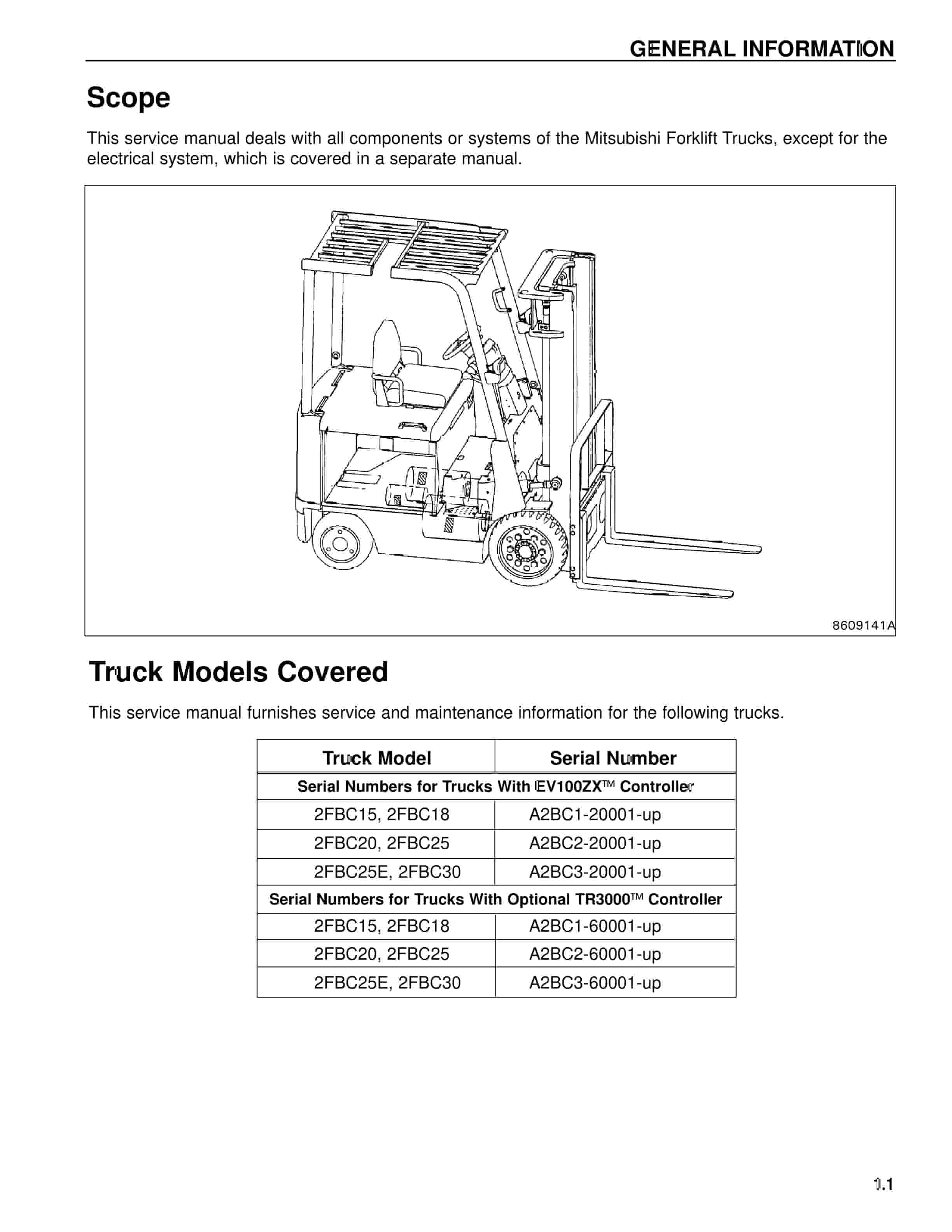
Mitsubishi 2FBC25 Forklift Service Manual
$50.00 Add to cart -
Mitsubishi 4G33, 4G52, 4G54 Service Manual 99719-42120
$50.00 Add to cart -
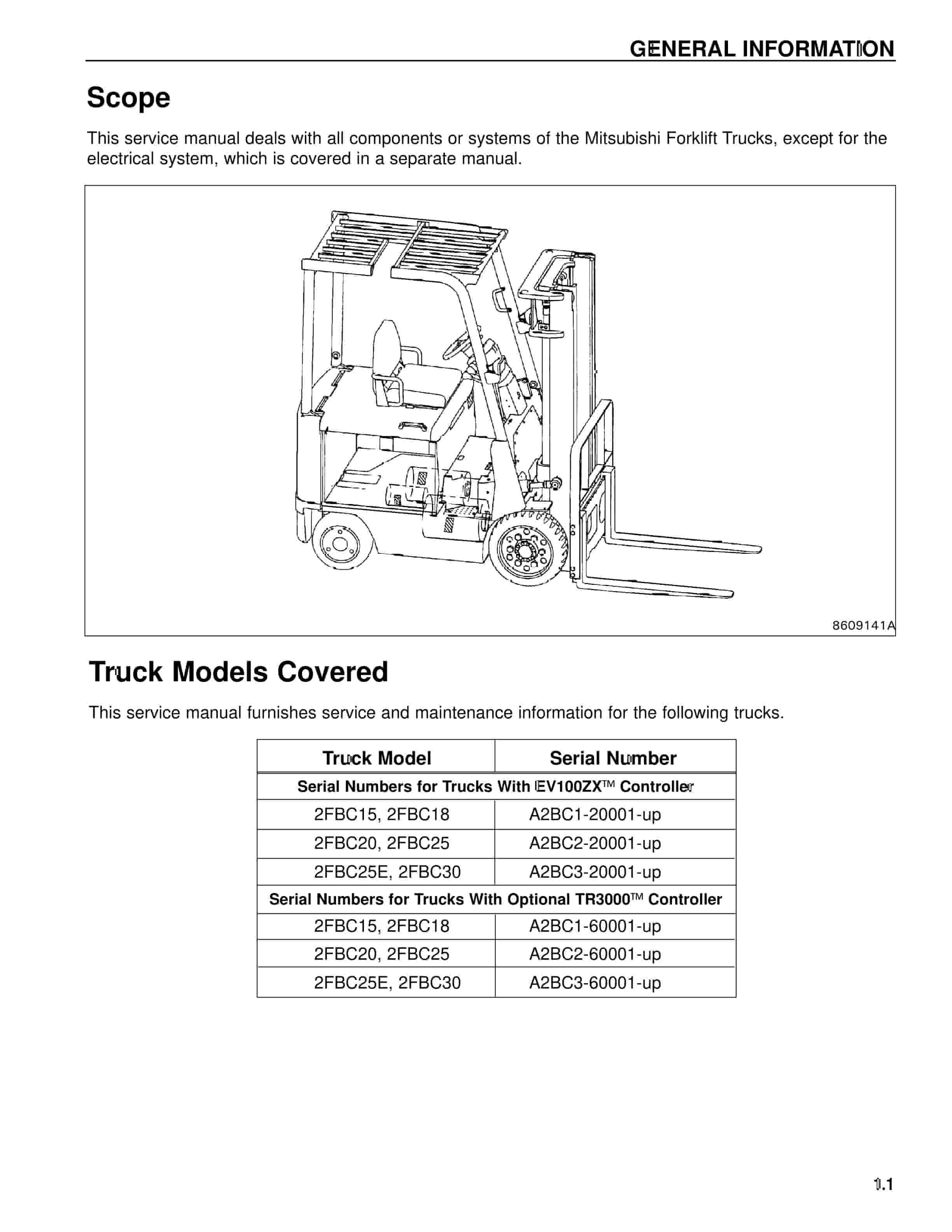
Mitsubishi 2FBC20 Forklift Service Manual
$50.00 Add to cart -
Mitsubishi 1204E Diesel Engine Troubleshooting Service Manual 99799-56104
$50.00 Add to cart -
Mitsubishi 1204E Diesel Engine Specifications Service Manual 99799-56101
$50.00 Add to cart


