

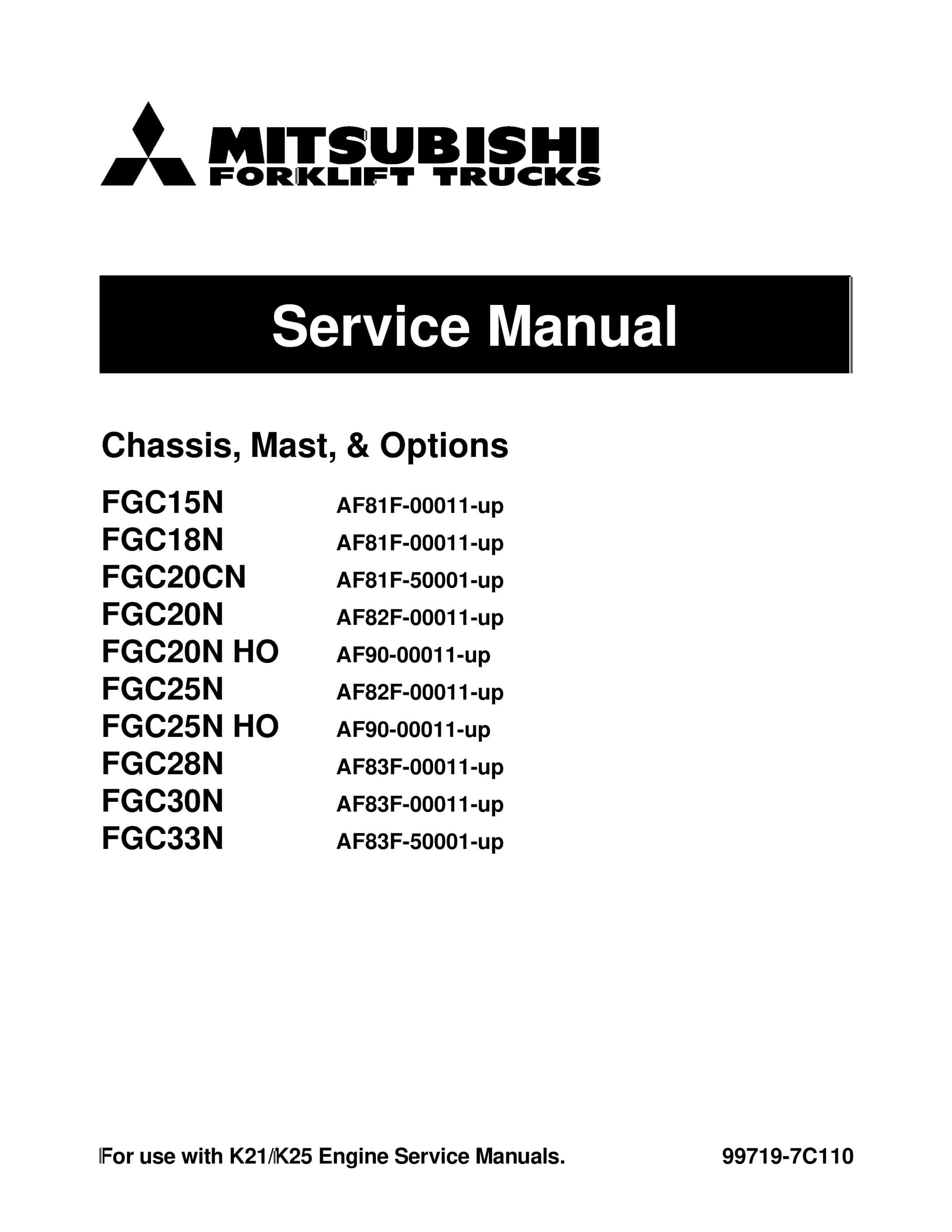


Mitsubishi FGC15N to FGC33N Chassis, Mast and Options Service Manual 99719-7C110
$50.00
- Type Of Manual: Service Manual
- Manual ID: 99719-7C110
- Number of Pages: 576
- Size: 10.2MB
- Format: PDF
Product details
-
Model List:
- FGC15N, FGC18N, FGC20CN, FGC20N, FGC20N-HO, FGC25N, FGC25N-HO, FGC28N, FGC30N, FGC33N
- 1. GENERAL INFORMATION
- 1.1. GENERAL INFORMATION
- 1.1.1. Model View
- 1.1.2. Truck Models Covered
- 1.1.3. Serial Number Locations
- 1.1.4. Dimensions
- 1.1.5. Technical Data
- 2. BRAKE SYSTEM
- 2.1. BRAKE SYSTEM
- 2.1.1. Structure
- 2.1.2. Disassembly and Reassembly
- 2.1.3. Inspection and Adjustment
- 2.1.4. Troubleshooting
- 2.1.5. Service Data
- 3. CONTROLERS
- 3.1. CONTROLLERS
- 3.1.1. Outline
- 3.1.2. Main Functions
- 3.1.3. Service Tool Functions
- 3.1.4. Locations of Sensors and Switches
- 4. COOLING SYSTEM
- 4.1. COOLING SYSTEM
- 4.1.1. Specification
- 4.1.2. Structure
- 4.1.3. Removal and Installation
- 4.1.4. Inspection and Adjustment
- 4.1.4.1. Unit Layout
- 4.1.4.2. Inspection and Adjustment
- 5. ELECTRICAL SYSTEM
- 5.1. ELECTRICAL SYSTEM
- 5.1.1. Chassis Electrical Devices Wiring Outline (No. 1)
- 5.1.2. Chassis Electrical Devices Wiring Outline (No. 2)
- 5.1.3. Structure
- 5.1.4. Console Box
- 5.1.5. Battery
- 5.1.6. Wire Color
- 5.1.7. Troubleshooting
- 5.1.8. Electrical Schematic ( 1 / 2 )
- 5.1.9. Electrical Schematic ( 2 / 2 )
- 6. FRONT AXLE AND REDUCTION DIFFERENTIAL
- 6.1. FRONT AXLE
- 6.1.1. Structure
- 6.1.2. Removal and Installation
- 6.1.3. Disassembly and Reassembly
- 6.1.4. Service Data
- 7. HYDRAULIC SYSTEM
- 7.1. HYDRAULIC SYSTEM
- 7.1.1. Structure and Functions
- 7.1.2. Disassembly and Reassembly
- 7.1.3. Inspection and Adjustment
- 7.1.4. Inspection and Adjustment
- 7.1.5. Troubleshooting
- 7.1.6. Service Data
- 7.1.7. Control Valve
- 7.1.8. Disassembly and Reassembly
- 8. MAST AND FORKS
- 8.1. MAST AND FORKS
- 8.1.1. Mast Systems
- 8.1.2. Structure
- 8.1.3. Removal and Installation
- 8.1.4. Disassembly and Reassembly
- 8.1.5. Duplex Mast
- 8.1.6. Triplex Mast
- 8.1.7. Inspection and Adjustment
- 8.1.8. Troubleshooting
- 8.1.9. Service Data
- 9. POWER TRAIN
- 9.1. POWER TRAIN
- 9.1.1. Removal and Installation
- 9.1.1.1. Removal of Engine and Transmission Assembly
- 9.1.1.2. Cooling, Exhaust and Hydraulic
- 9.1.1.3. Front Wheel and Front Axle Shaft
- 9.1.1.4. Engine and Transmission Assembly
- 9.1.2. Installation
- 10. POWERSHIFT TRANSMISSION
- 10.1. POWERSHIFT TRANSMISSION
- 10.1.1. Structure and Function
- 10.1.2. Removal and Installation
- 10.1.3. Control Valve
- 10.1.4. Input Shaft Assembly
- 10.1.5. Oil Pump Assembly
- 10.1.6. Inspection and Adjustment
- 10.1.7. Troubleshooting
- 10.1.8. Tightening Torque
- 10.1.9. Service Data
- 11. REAR AXLE
- 11.1. REAR AXLE
- 11.1.1. Structure and Functions
- 11.1.2. Removal and Installation
- 11.1.3. Disassembly and Reassembly
- 11.1.4. Troubleshooting
- 11.1.5. Service Data
- 12. REDUCTION DIFFERENTIAL
- 12.1. REDUCTION DIFFERENTIAL
- 12.1.1. Structure and Function
- 12.1.2. Removal and Installation
- 12.1.3. Disassembly and Reassembly
- 12.1.4. Inspection
- 12.1.5. Reassembly
- 12.1.6. Troubleshooting
- 13. SERVICE DATA
- 13.1. SERVICE DATA
- 13.1.1. Maintenance Schedule
- 13.1.2. Tightening Torques for Standard Bolts and Nuts
- 13.1.3. Parts to be Changed Periodically
- 13.1.4. Lubrication Instructions
- 13.1.5. Fuel and Lubricant Specifications
- 13.1.6. Refill Capacities
- 13.1.7. Weight of Components (Approximate)
- 13.1.8. Special Service Tool
- 14. STEERING SYSTEM
- 14.1. STEERING SYSTEM
- 14.1.1. Structure and Function
- 14.1.2. Steering Column
- 14.1.3. Disassembly and Reassembly
- 14.1.4. Removal and Installation of Steering Wheel and Steering Valve
- 14.1.5. Steering Valve
- 14.1.6. Troubleshooting
- 14.1.7. Service Data
- 15. ENGINE CONTROL
- 15.1. ENGINE CONTROL
- 15.1.1. PRECAUTIONS
- 15.1.1.1. General precautions for service operations
- 15.1.2. PREPARATION
- 15.1.2.1. Service Tools
- 15.1.3. DESCRIPTION
- 15.1.4. BASIC INSPECTION
- 15.1.4.1. Inspection of Idle Speed, Ignition Timing, and Air-fuel Ratio
- 15.1.4.2. Throttle Valve Closed Position Learning and Idle Air Volume Learning
- 15.1.4.3. Accelerator Pedal Released Position Learning
- 15.1.4.4. Fuel pressure inspection EC
- 15.1.5. TROUBLE DIAGNOSIS
- 15.1.5.1. How to Proceed with Trouble Diagnosis
- 15.1.5.2. Diagnosis Chart by Symptom
- 15.1.5.3. Component Parts Location
- 15.1.5.4. ECM Component
- 15.1.5.5. Circuit Diagram
- 15.1.5.6. ECM Terminal Layout
- 15.1.5.7. ECM Input/Output Signal Specifications
- 15.1.5.8. Service Tool (ST)
- 15.1.5.9. Self-Diagnosis Function (without ST)
- 15.1.5.10. ST Reference Value in Data Monitor
- 15.1.5.11. Fail-Safe Function
- 15.1.6. POWER SUPPLY AND GROUND SYSTEM
- 15.1.6.1. ECM Input/Output Signal Specifications
- 15.1.6.2. Circuit Diagram
- 15.1.7. CRANKSHAFT POSITION SENSOR (POS) SYSTEM
- 15.1.7.1. ECM Input/Output Signal Specifications
- 15.1.7.2. Circuit Diagram
- 15.1.7.3. Component Parts Inspection
- 15.1.8. CAMSHAFT POSITION SENSOR (PHASE) SYSTEM
- 15.1.8.1. ECM Input/Output Signal Specifications
- 15.1.8.2. Circuit Diagram
- 15.1.8.3. Component Parts Inspection
- 15.1.9. MASS AIR FLOW SENSOR SYSTEM
- 15.1.9.1. ST Data Monitor Display
- 15.1.9.2. ECM Input/Output Signal Specifications
- 15.1.9.3. Circuit Diagram
- 15.1.9.4. Component Parts Inspection
- 15.1.10. ENGINE COOLANT TEMPERATURE SENSOR SYSTEM
- 15.1.10.1. ST Data Monitor Display
- 15.1.10.2. ECM Input/Output Signal Specifications
- 15.1.10.3. Circuit Diagram
- 15.1.10.4. Component Parts Inspection
- 15.1.11. HEATED OXYGEN SENSOR SYSTEM
- 15.1.11.1. ST Data Monitor Display
- 15.1.11.2. ECM Input/Output Signal Specifications
- 15.1.11.3. Circuit Diagram
- 15.1.12. THROTTLE POSITION SENSOR SYSTEM
- 15.1.12.1. ST Data Monitor Display
- 15.1.12.2. ECM Input/Output Signal Specifications
- 15.1.12.3. Circuit Diagram
- 15.1.12.4. Component Parts Inspection
- 15.1.13. ACCELERATOR PEDAL POSITION SENSOR SYSTEM
- 15.1.13.1. ST Data Monitor Display
- 15.1.13.2. ECM Input/Output Signal Specifications
- 15.1.13.3. Circuit Diagram
- 15.1.13.4. Component Parts Inspection
- 15.1.14. INTAKE AIR TEMPERATURE SENSOR
- 15.1.14.1. ST Data Monitor Display
- 15.1.14.2. ECM Input/Output Signal Specifications
- 15.1.14.3. Circuit Diagram
- 15.1.14.4. Component Parts Inspection
- 15.1.15. PNP SWITCH SYSTEM
- 15.1.15.1. ST Data Monitor Display
- 15.1.15.2. ECM Input/Output Signal Specifications
- 15.1.15.3. Circuit Diagram
- 15.1.16. STOP LAMP SWITCH SYSTEM
- 15.1.16.1. ST Data Monitor Display
- 15.1.16.2. ECM Input/Output Signal Specifications
- 15.1.16.3. Circuit Diagram
- 15.1.16.4. Component Parts Inspection
- 15.1.17. ELECTRIC LOAD SWITCH SYSTEM
- 15.1.17.1. ST Data Monitor Display
- 15.1.17.2. ECM Input/Output Signal Specifications
- 15.1.17.3. Circuit Diagram
- 15.1.18. CAN COMMUNICATION SYSTEM
- 15.1.18.1. ECM Input/Output Signal Specifications
- 15.1.18.2. Circuit Diagram
- 15.1.19. IGNITION SYSTEM
- 15.1.19.1. ST Data Monitor Display
- 15.1.19.2. ECM Input/Output Signal Specifications
- 15.1.19.3. Circuit Diagram
- 15.1.19.4. Component Parts Inspection
- 15.1.20. FUEL INJECTOR SYSTEM
- 15.1.20.1. ST Data Monitor Display
- 15.1.20.2. ECM Input/Output Signal Specifications
- 15.1.20.3. Circuit Diagram
- 15.1.20.4. Component Parts Inspection
- 15.1.21. FUEL PUMP SYSTEM
- 15.1.21.1. ST Data Monitor Display
- 15.1.21.2. ECM Input/Output Signal Specifications
- 15.1.21.3. Circuit Diagram
- 15.1.21.4. Component Parts Inspection
- 15.1.22. THROTTLE CONTROL MOTOR SYSTEM
- 15.1.22.1. ECM Input/Output Signal Specifications
- 15.1.22.2. Circuit Diagram
- 15.1.22.3. Component Parts Inspection
- 15.1.23. HEATED OXYGEN SENSOR HEATER SYSTEM
- 15.1.23.1. ST Data Monitor Display
- 15.1.23.2. ECM Input/Output Signal Specifications
- 15.1.23.3. Circuit Diagram
- 15.1.23.4. Component Parts Inspection
- 15.1.24. PCV GAS RECIRCULATION DEVICE
- 15.1.24.1. System Diagram
- 15.1.24.2. Component Parts Inspection
- 15.1.25. FUEL CUT FUNCTION
- 15.1.25.1. Inspection Procedure
- 15.1.26. REMOVAL AND INSTALLATION OF ECM COMPONENTS
- 15.1.26.1. Removal and Installation of ECM
- 15.1.26.2. Removal and Installation of Crankshaft Position Sensor (POS)
- 15.1.26.3. Removal and Installation of Camshaft Position Sensor (PHASE)
- 15.1.26.4. Removal and Installation of Mass Air Flow Sensor
- 15.1.26.5. Removal and Installation of Engine Coolant Temperature Sensor
- 15.1.26.6. Removal and Installation of Heated Oxygen Sensor (with Heated Oxygen Sensor Heater)
- 15.1.26.7. Removal and Installation of Throttle Position Sensor (Electric Throttle Control Actuator Assembly)
- 15.1.26.8. Removal and Installation of Accelerator Pedal Position Sensor (Accelerator Pedal Assembly)
- 15.1.26.9. Removal and Installation of Intake Air Temperature Sensor (with Mass Air Flow Sensor)
- 15.1.26.10. Removal and Installation of Neutral Switch (M/T Model)
- 15.1.26.11. Removal and Installation of Ignition Coil (with Power Transistor)
- 15.1.26.12. Removal and Installation of Fuel Injector
- 15.1.26.13. Removal and Installation of Fuel Pump
- 15.1.26.14. Removal and Installation of Throttle Control Motor (Electric Throttle Control Actuator Assembly)
- 15.1.26.15. Removal and Installation of LPG Injector Holder
- 15.1.26.16. Removal and Installation of LPG Injector Drive Unit
- 15.1.27. SERVICE DATA AND SPECIFICATIONS (SDS)
- 15.1.27.1. Standard, Repair Limit
- 16. ENGINE ELECTRICAL
- 16.1. ENGINE ELECTRICAL SYSTEM
- 16.1.1. ADJUSTMENT VALUE
- 16.1.2. TROUBLE DIAGNOSIS
- 16.1.3. STARTER MOTOR
- 16.1.3.1. Starter Motor Specifications
- 16.1.3.2. Component Parts Location
- 16.1.3.3. Overhaul
- 16.1.3.4. Assembly Inspection
- 16.1.4. ALTERNATOR
- 16.1.4.1. Components of Alternator
- 16.1.4.2. Disassembly
- 16.1.4.3. Inspection
- 17. ENGINE FUEL
- 17.1. ENGINE FUEL
- 17.1.1. EMISSION CONTROL SYSTEM (ONLY FOR ELECTRONIC CONTROLLED TYPE)
- 17.1.2. UNIT LAYOUT
- 17.1.3. SERVICE DATA AND SPECIFICATIONS (SDS)
- 17.1.3.1. Electronic Control System Specifications
- 17.1.4. LPG FUEL SYSTEM TROUBLE DIAGNOSIS
- 17.1.5. DISASSEMBLY AND ASSEMBLY OF FUEL SYSTEM
- 17.1.5.1. Removal and Installation of LPG Injector Drive Unit Connector
- 17.1.5.2. Removal and Installation of Electronic Control Throttle Assembly
- 17.1.5.3. Removal and Installation of Gasoline Fuel Injector (Electronic Controlled Gasoline and Combined Use)
- 17.1.5.4. Injector Holder
- 17.1.6. VAPORIZER MECHANISM AND OPERATION
- 17.1.6.1. Primary (Decompression) Room
- 17.1.6.2. Description
- 18. ENGINE LUBRICATION AND COOLING SYSTEM
- 18.1. ENGINE LUBRICATION COOLING SYSTEMS
- 18.1.1. LUBRICATION SYSTEM
- 18.1.1.1. Specifications
- 18.1.1.2. Adjustment Value
- 18.1.1.3. Oil Pressure
- 18.1.1.4. Tightening Torque
- 18.1.1.5. Trouble Diagnosis
- 18.1.1.6. Lubrication Schematic Diagram
- 18.1.1.7. Oil Pump
- 18.1.2. ENGINE COOLANT SYSTEM
- 18.1.2.1. Specifications
- 18.1.2.2. Adjustment Value
- 18.1.2.3. Tightening Torque
- 18.1.2.4. Trouble Diagnosis
- 18.1.2.5. Cooling System Configuration
- 18.1.2.6. Water Pump
- 18.1.2.7. Thermostat
- 19. ENGINE MECHANICAL
- 19.1. ENGINE MECHANICAL
- 19.1.1. PRECAUTIONS
- 19.1.1.1. Precautions for Draining Engine Coolant
- 19.1.1.2. Precautions for Disconnecting Fuel Piping
- 19.1.1.3. Precautions for Removing and Disassembling
- 19.1.1.4. Precautions for Inspection, Correction, and Replacement
- 19.1.1.5. Precautions for Assembly and Installation
- 19.1.1.6. Parts Requiring Angle Tightening
- 19.1.1.7. Caution for Use of Power Tools
- 19.1.1.8. Precautions for Liquid Gasket Application
- 19.1.2. ENGINE OUTSIDE DRAWINGS
- 19.1.3. MAIN SPECIFICATIONS
- 19.1.4. ADJUSTMENT VALUE
- 19.1.5. TIGHTENING TORQUE
- 19.1.5.1. Standard Bolt Tightening Torque
- 19.1.5.2. Engine Part Tightening Torque
- 19.1.6. TROUBLE DIAGNOSIS
- 19.1.7. SERVICE TOOLS
- 19.1.8. REMOVAL AND INSTALLATION OF ENGINE
- 19.1.8.1. Removal
- 19.1.8.2. Installation
- 19.1.8.3. Inspection
- 19.1.9. ENGINE SERVICE
- 19.1.9.1. Engine Disassembly
- 19.1.9.2. Inspection and Correction
- 19.1.9.3. Engine Assembly
- 20. ENGINE TUNE-UP
- 20.1. ENGINE TUNE-UP
- 20.1.1. SPECIFICATIONS
- 20.1.2. TIGHTENING TORQUE
- 20.1.3. TROUBLE DIAGNOSIS
- 20.1.4. ENGINE INSPECTION AND ADJUSTMENT
- 20.1.4.1. Engine Body Related
- 20.1.4.2. Ignition and Fuel Systems
- 21. FOREWORD
- 21.1. FOREWORD
- 21.2. GROUP INDEX
- 22. GENERAL INFORMATION
- 22.1. GENERAL INFORMATION
- 22.1.1. HOW TO USE THIS MANUAL
- 22.1.1.1. Description
- 22.1.1.2. Definition of Terms
- 22.1.1.3. Definition of Units
- 22.1.1.4. Description
- 22.1.2. PRECAUTIONS FOR SAFETY AND QUALITY
- 22.1.2.1. Reduction of Risk Operation
- 22.1.2.2. Correct Operation
- 22.1.2.3. Precautions for Radio Equipment Installation
- 22.1.3. PRECAUTIONS
- 22.1.3.1. Precautions in Draining Engine Coolant
- 22.1.3.2. Precautions for Disconnecting Fuel Piping
- 22.1.3.3. Precautions for Removing and Disassembling
Related products
-
Mitsubishi 1204E Diesel Engine Troubleshooting Service Manual 99799-56104
$50.00 Add to cart -
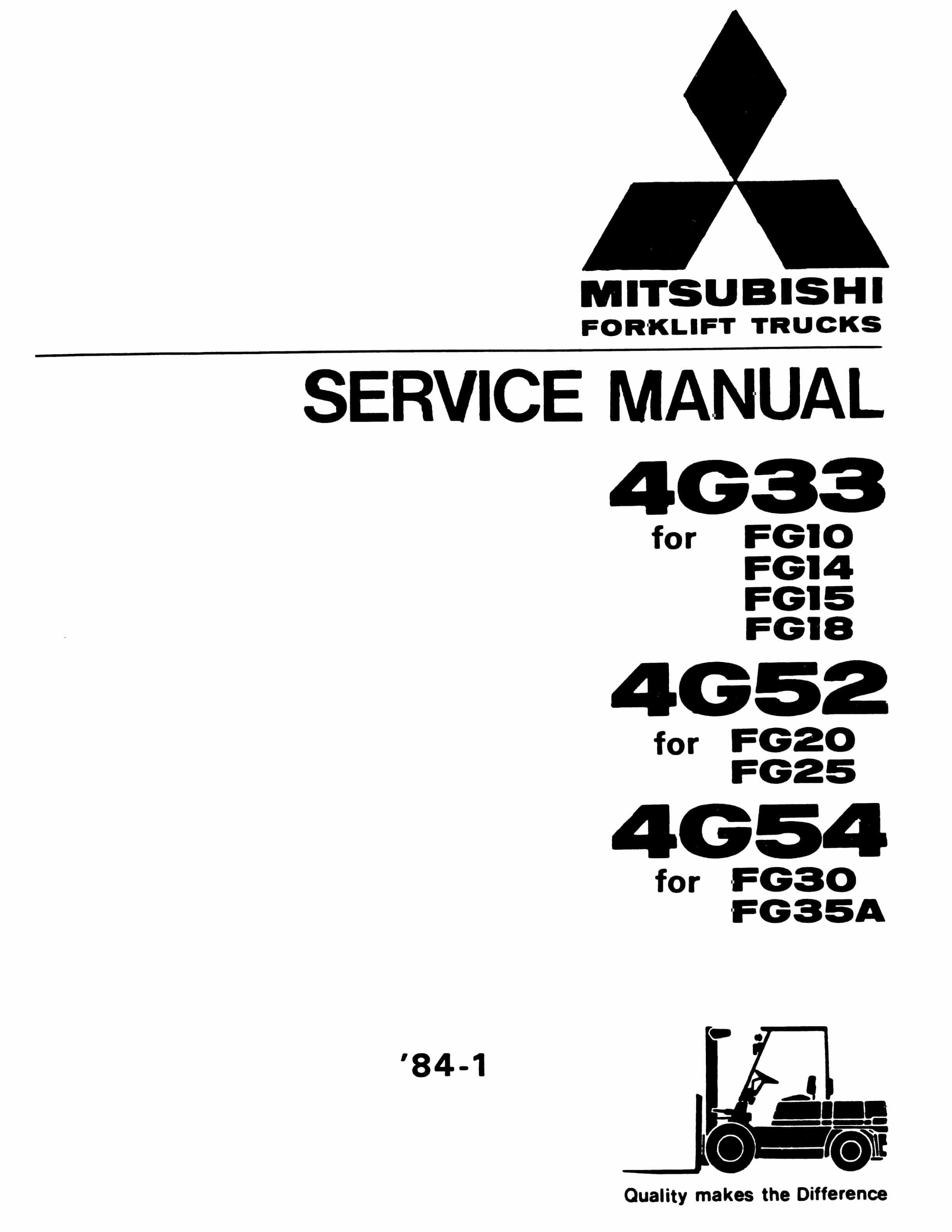
Mitsubishi 4G33, 4G52, 4G54 Service Manual 99719-42120
$50.00 Add to cart -
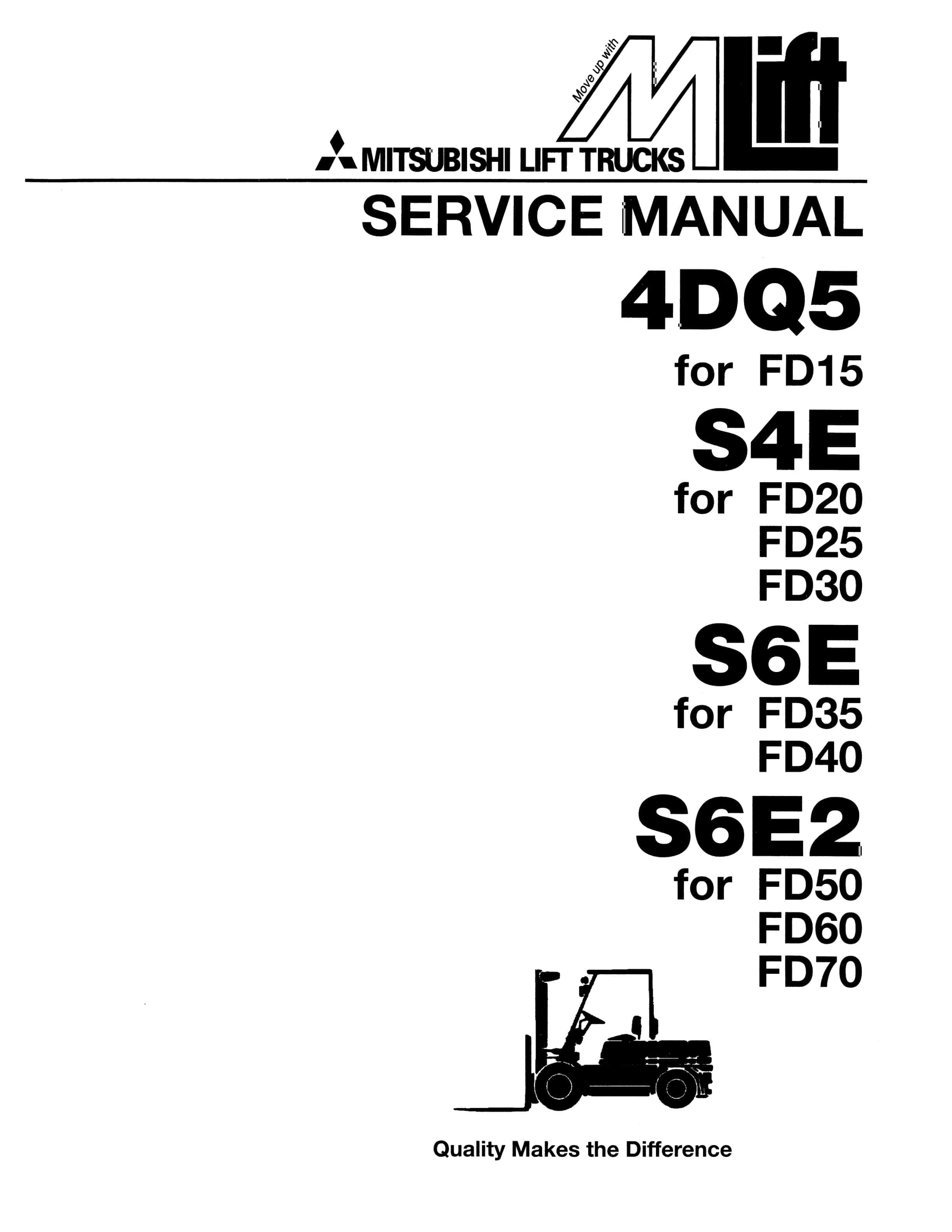
Mitsubishi 4DQ5, S4E, S6E, S6E2 Service Manual 99719-52120
$50.00 Add to cart -
Mitsubishi PSI 4X LPG Engine Service Manual 99739-7C100
$50.00 Add to cart -
Mitsubishi 1204E Diesel Engine Operation and Maintenance Manual Service Manual 99799-56105
$50.00 Add to cart


