

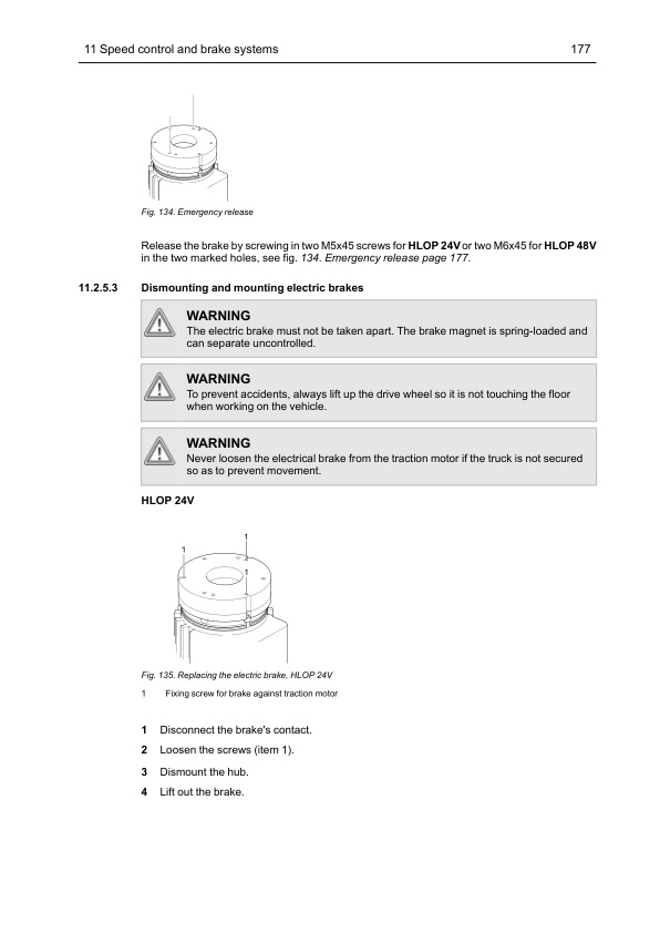
Mitsubishi OPBM10P, OPBH12PH Service Manual SM23GBEPMHA1
$50.00
- Type Of Manual: Service Manual
- Manual ID: SM23GBEPMHA1
- Number of Pages: 226
- Size: 13.0MB
- Format: PDF
Product details
-
Model List:
- OPBM10P, OPBH12PH
- 1. GENERAL INFORMATION AND TECHNICAL DATA
- 1.1. Introduction
- 1.1.1. General
- 1.1.2. The trucks
- 1.1.3. Genuine Parts
- 1.1.4. Authorised service personnel
- 1.1.5. Symbol key
- 1.2. Safety
- 1.2.1. General
- 1.2.2. Safety instructions
- 1.2.3. Truck modification
- 1.2.4. Lifting the truck
- 1.2.5. Welding on truck
- 1.3. Environmental considerations
- 1.3.1. We respect the environment
- 1.4. Preparations
- 1.4.1. Service
- 1.4.2. Troubleshooting
- 1.5. Truck data
- 1.5.1. Machine plates
- 1.5.2. Safety and warning signs
- 1.5.3. Explanation of symbols
- 1.5.4. Type designation
- 1.5.5. Truck types
- 1.5.6. Dimensions and weights
- 1.6. Component placement
- 1.6.1. HLOP 24V
- 1.6.2. HLOP 48V
- 1.7. Component specification
- 1.7.1. Drive motor
- 1.7.2. Electric brake
- 1.7.3. Gearbox
- 1.7.4. Hydraulic unit
- 1.7.5. Control system for traction and pump motors
- 1.7.6. Steering servo motor
- 1.7.7. Controller system for steering
- 1.8. Recommended consumable materials
- 1.8.1. Oil and grease types
- 1.9. Code explanations
- 1.9.1. Colour codes for wiring diagrams
- 1.9.2. Designations for electrical components in electrical diagram
- 1.9.3. Standard abbreviations and units
- 1.9.4. Acronyms and abbreviations
- 2. SPECIAL TOOLS
- 2.1. List of tools
- 3. SERVICE
- 3.1. Service schedule / inspection
- 3.1.1. Introduction
- 3.1.2. Safety
- 3.1.3. Service schedule explanation
- 3.1.4. Inspection daily / monthly / PDI and commissioning
- 3.1.5. First service (200 hours)
- 3.1.6. Main service
- 3.1.7. Extra service inspections
- 3.1.8. Service inspection
- 3.1.9. Dye penetration inspection instruction
- 3.2. Service schedule
- 3.3. Lubrication
- 3.3.1. Recommended lubricants
- 3.3.2. Symbol key, lubrication chart
- 3.3.3. Lubrication chart
- 4. CHASSIS
- 4.1. Design and function
- 4.1.1. Machine housing
- 4.1.2. Overhead guard
- 4.1.3. Battery locking
- 4.1.4. Covers and panels
- 4.2. Repair and maintenance instructions
- 4.2.1. Before work is performed
- 4.2.2. Removal and installation of the overhead guard
- 4.2.3. Panels and housing
- 4.2.4. Battery lock adjustment, HLOP 48V
- 4.2.5. Removal and installation of the battery rollers
- 4.2.6. Remove and install the foot plate
- 4.2.7. Tilt the truck before changing wheels
- 4.2.8. Replacing the load wheels, HLOP 24/48V
- 4.2.9. Adjustment of stabilising lugs, HLOP 48V
- 5. DRIVE UNIT
- 5.1. Design and function
- 5.1.1. Description
- 5.1.2. Drive motor
- 5.1.3. Gearbox
- 5.1.4. Drive wheel
- 5.2. Repair and maintenance instructions
- 5.2.1. Before work is performed
- 5.2.2. Servicing and maintenance
- 5.3. Drive unit, HLOP 24V
- 5.3.1. Traction motor
- 5.3.2. Gearbox
- 5.3.3. Drive wheels
- 5.4. Drive unit, HLOP 48V
- 5.4.1. Drive motor
- 5.4.2. Gearbox
- 5.4.3. Drive wheel
- 5.5. Diagnostics and troubleshooting
- 5.5.1. Troubleshooting
- 5.5.2. Troubleshooting chart
- 6. MAST SYSTEM
- 6.1. Design and function
- 6.1.1. Fixation of the mast
- 6.1.2. Operators platform
- 6.1.3. Mast switch in mast
- 6.2. Repair and maintenance instructions
- 6.2.1. Before work is performed
- 6.2.2. Operators platform
- 6.2.3. Fork carriage
- 6.2.4. Lift chains
- 6.2.5. Control of initial lift stroke
- 6.2.6. Inspection of forks
- 6.2.7. Emergency lowering valve
- 6.3. Diagnostics and troubleshooting
- 6.3.1. Troubleshooting
- 7. STEERING
- 7.1. Design and function
- 7.1.1. General
- 7.1.2. Feedback sensors
- 7.1.3. Communication between the servo components
- 7.2. Repair and maintenance instructions
- 7.2.1. Before work is performed
- 7.2.2. Steering wheel
- 7.2.3. Steering servo motor
- 7.2.4. Remove and install the zero position sensor
- 7.2.5. Adjustments and tests
- 7.3. Diagnostics and troubleshooting
- 8. HYDRAULIC SYSTEM
- 8.1. Design and function
- 8.1.1. Description, HLOP 24/48V
- 8.1.2. Functions
- 8.1.3. Hydraulic diagram
- 8.1.4. Hydraulic unit, pump motor, HLOP 24/48V
- 8.1.5. Valve unit, HLOP 24/48V
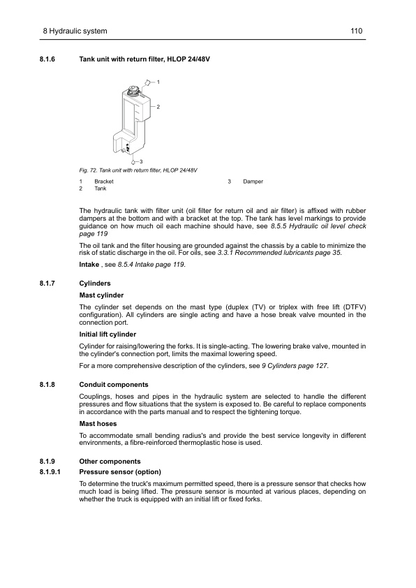
- 8.1.6. Tank unit with return filter, HLOP 24/48V
- 8.1.7. Cylinders
- 8.1.8. Conduit components
- 8.1.9. Other components
- 8.1.10. Hydraulic oil
- 8.2. Repair and maintenance instructions
- 8.2.1. Before work is performed
- 8.2.2. General rules
- 8.2.3. Installation
- 8.2.4. Connections
- 8.2.5. Dismounting and mounting of hydraulic hoses
- 8.3. Hydraulic unit, pump motor, HLOP 24/48V
- 8.3.1. Removal and installation of the hydraulic unit (pump motor unit)
- 8.3.2. Removal and installation of the pump
- 8.3.3. Removal and installation of the motor bearing
- 8.3.4. Start after work with the pump motor unit
- 8.4. Valve unit, HLOP 24/48V
- 8.4.1. Overview
- 8.4.2. Tightening torque
- 8.4.3. Cold resistance values, coils
- 8.4.4. Removal and installation of valve unit
- 8.4.5. Start after work with the valve unit
- 8.4.6. Pressure limitation, control and setting
- 8.4.7. Check of lowering speed
- 8.5. Tank and filter unit, HLOP 24/48V
- 8.5.1. General
- 8.5.2. Replacing the air filter
- 8.5.3. Replacing the oil filter
- 8.5.4. Intake
- 8.5.5. Hydraulic oil level check
- 8.5.6. Changing the oil
- 8.5.7. Removal and installation of the hydraulic tank
- 8.6. Diagnostics and troubleshooting
- 8.6.1. TruckTool
- 8.6.2. Troubleshooting
- 8.6.3. Troubleshooting, hydraulics functions, HLOP 24/48V
- 9. CYLINDERS
- 9.1. Design and function
- 9.1.1. Descriptions
- 9.1.2. Damping
- 9.1.3. Hose break valve
- 9.2. Repair and maintenance instructions
- 9.2.1. Before work is performed
- 9.2.2. Bleeding of the hydraulic cylinders without a bleed air screw
- 9.2.3. Bleeding of the hydraulic cylinders with an air bleed screw
- 9.2.4. Work with hose break valve/lowering brake valve in cylinders
- 9.2.5. Replace seals, lift cylinder
- 9.3. Cylinders, HLOP 24/48V
- 9.3.1. Removing and installing the free lift cylinder, triplex with free lift (DTFV) mast
- 9.3.2. Removing and installing the mast lift cylinder, duplex (TV) mast
- 9.3.3. Removing and installing the mast lift cylinder, triplex with free lift (DTFV) mast
- 9.3.4. Removing and installing the initial cylinder
- 9.3.5. Aeration of the initial cylinder
- 10. ELECTRICAL SYSTEM
- 10.1. Introduction
- 10.1.1. Overview of components
- 10.1.2. CAN bus communication
- 10.2. Safety
- 10.2.1. Safety instructions
- 10.2.2. Electronic controllers
- 10.2.3. Safety checks
- 10.2.4. Steering servo system
- 10.2.5. Hydraulic system
- 10.2.6. Traction speed system
- 10.2.7. Sensors
- 10.2.8. Safety controls, weight measurement system
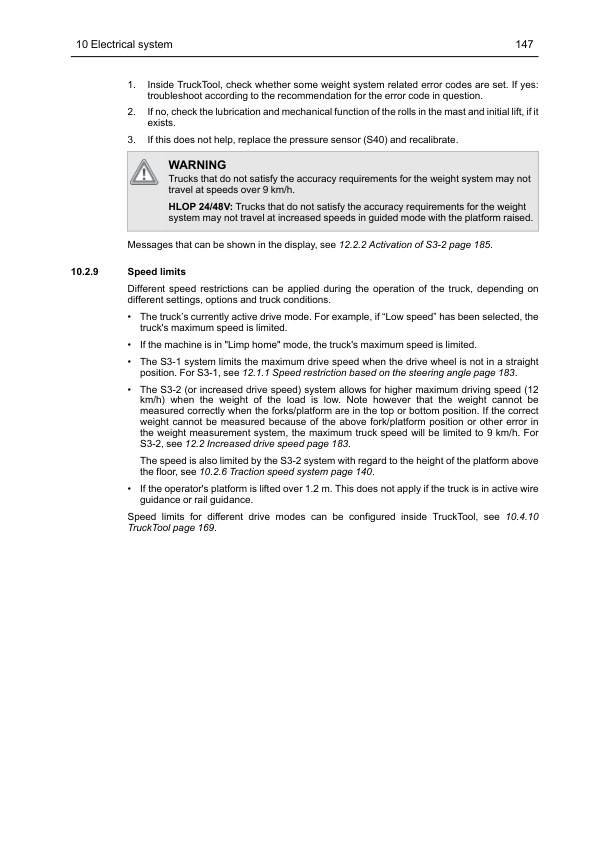
- 10.2.9. Speed limits
- 10.3. Design and function
- 10.3.1. Battery replacement
- 10.3.2. Battery capacity
- 10.3.3. VCM (Vehicle Control Module) (truck computer)
- 10.3.4. Display and icon panel
- 10.3.5. TMC (Traction Motor Controller)
- 10.3.6. PMC (Pump Motor Controller)
- 10.3.7. EPS (Electrical Power Steering) controller
- 10.3.8. Hydraulic system
- 10.3.9. Brake system
- 10.3.10. Traction system
- 10.3.11. Connector specifications
- 10.4. Repair and maintenance instructions
- 10.4.1. Before work is performed
- 10.4.2. Connectors in cold store
- 10.4.3. Wiring diagram
- 10.4.4. Insulation test
- 10.4.5. Remove and install the VCM
- 10.4.6. Remove and install the multi function display (HMI-20)
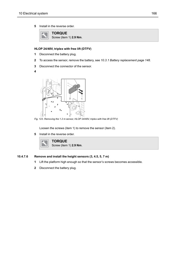
- 10.4.7. Remove and install the safety sensors
- 10.4.8. Cold resistance values, coils
- 10.4.9. TruckTool
- 10.5. Diagnostics and troubleshooting
- 11. SPEED CONTROL AND BRAKE SYSTEMS
- 11.1. Design and function
- 11.1.1. General
- 11.1.2. Speed and brake control
- 11.1.3. Electric brakes
- 11.1.4. Brake button
- 11.1.5. Motor brake
- 11.2. Repair and maintenance instructions
- 11.2.1. Before work is performed
- 11.2.2. Speed Controller
- 11.2.3. Brake button
- 11.2.4. Removal and installation of the left hand control
- 11.2.5. Electric brakes
- 11.3. Diagnostics and troubleshooting
- 11.3.1. Troubleshoot the speed controller
- 11.3.2. Troubleshoot the brake
- 12. MISCELLANEOUS
- 12.1. Stability support system, Cornering control
- 12.1.1. Speed restriction based on the steering angle
- 12.1.2. Dynamic cornering control
- 12.1.3. Settings DCC
- 12.2. Increased drive speed
- 12.2.1. Design and function
- 12.2.2. Activation of Increased drive speed
- 12.2.3. Calibration of Weight system
- 12.3. Lift and travel speed reduction/stop
- 12.4. Step warning
- 12.4.1. Design and function
- 12.4.2. Activation Step out warning option
- 12.5. Dual controls
- 12.5.1. Design and function
- 12.5.2. Maintenance and repair instructions
- 12.5.3. Diagnostics and troubleshooting
- 12.6. Wire guidance
- 12.6.1. Wire guidance antenna
- 12.6.2. Steering lock, wire guidance, HLOP 24/48V
- 12.6.3. Removing/installing the antenna
- 12.6.4. Select setting
- 12.6.5. Calibration
- 12.6.6. Troubleshooting
- 12.7. End of Aisle
- 12.7.1. General
- 12.7.2. Introduction
- 12.7.3. Installation
- 12.7.4. Settings
- 12.7.5. End of Aisle magnetic system troubleshooting
- 12.8. Rail guidance
- 12.8.1. Design and function
- 12.8.2. Repair and maintenance instructions
- 12.8.3. Diagnostics and troubleshooting
- 12.9. Descent with the help of safety line, option HLOP 24/48V
- 12.10. Mast lowering
- 12.11. Delivery mode, HLOP 24/48V
- 12.12. Mast raising, HLOP 24/48V
- 12.13. PPS, Personnel Protection System
Related products
-
Mitsubishi 4DQ5, S4E, S4E2 Service Manual 99719-52130
$50.00 Add to cart -
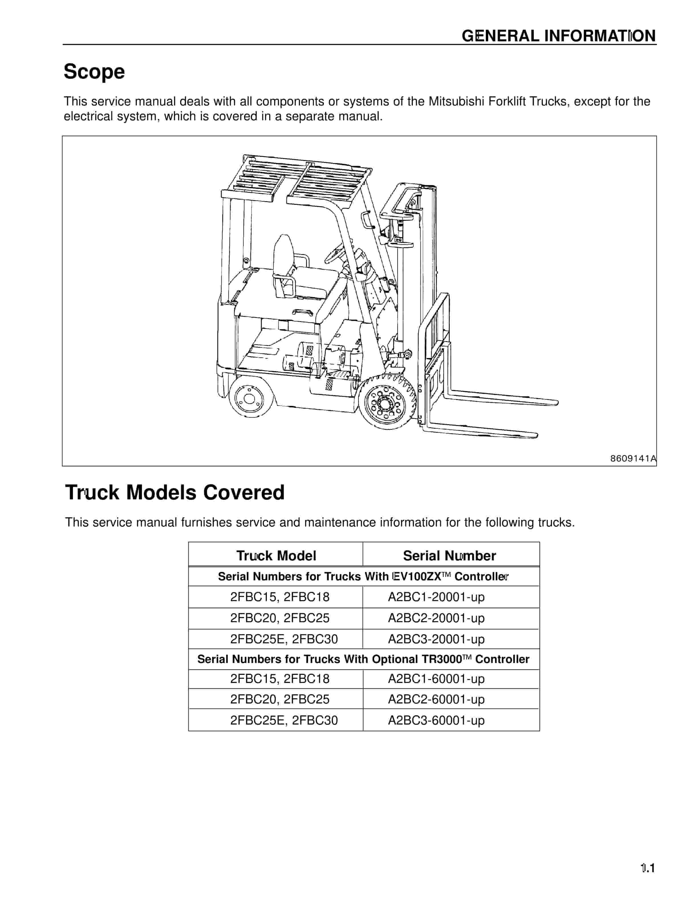
Mitsubishi 2FBC18 Forklift Service Manual
$50.00 Add to cart -
Mitsubishi 4G15 Gasoline Engine Service Manual 99719-16110
$50.00 Add to cart -
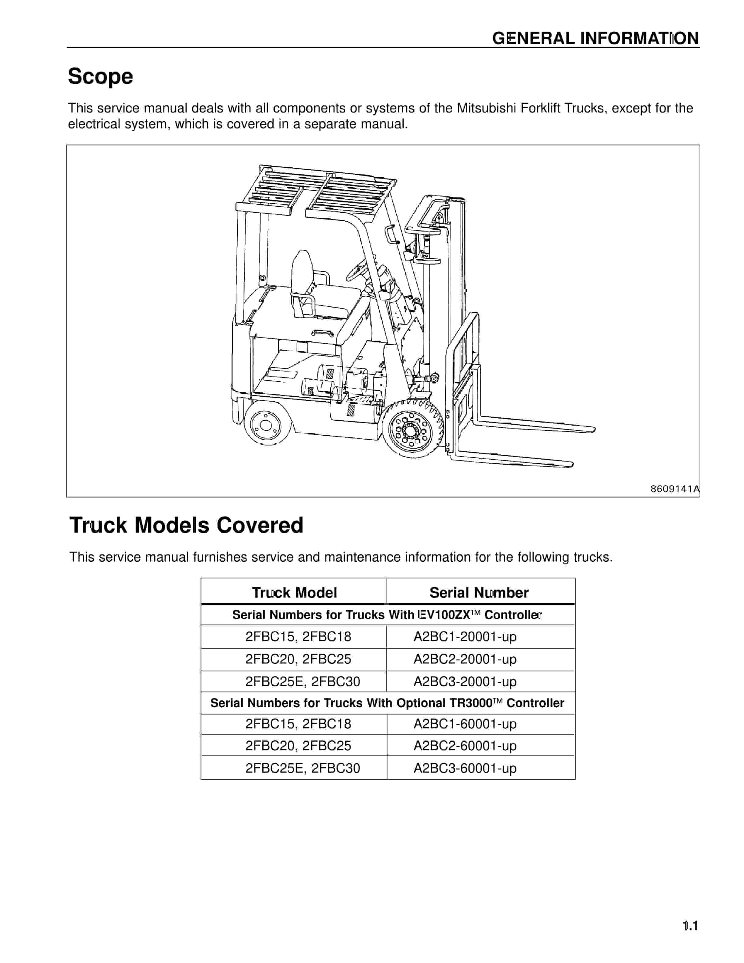
Mitsubishi 2FBC25 Forklift Service Manual
$50.00 Add to cart -
Mitsubishi 4G63, 4G64 Gasoline Engine Service Manual 99729-74120
$50.00 Add to cart


