

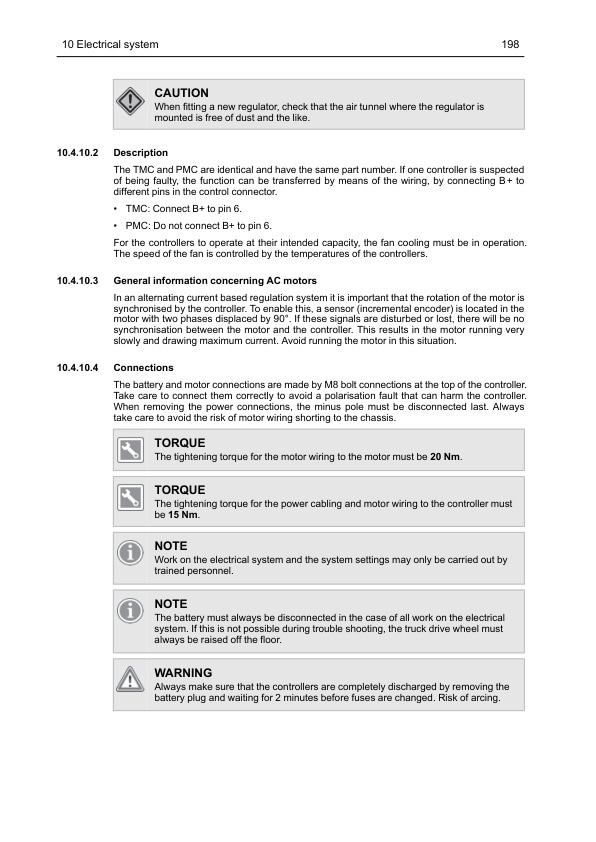
Mitsubishi RB12N3L to RB20N3HX Service Manual SM24GBUN01A2
$50.00
- Type Of Manual: Service Manual
- Manual ID: SM24GBUN01A2
- Number of Pages: 252
- Size: 9.7MB
- Format: PDF
Product details
-
Model List:
- RB12N3L, RB14N3L, RB14N3C, RB16N3, RB20N3, RB16N3H, RB20N3H, RB25N3H, RB20N3HX
- 1. GENERAL INFORMATION AND TECHNICAL DATA
- 1.1. Introduction
- 1.1.1. General
- 1.1.2. The trucks
- 1.1.3. Genuine Parts
- 1.1.4. Authorised service personnel
- 1.1.5. Symbol key
- 1.2. Safety
- 1.2.1. General
- 1.2.2. Safety instructions
- 1.2.3. Truck modification
- 1.2.4. Lifting the truck
- 1.2.5. Welding on truck
- 1.3. Environmental considerations
- 1.3.1. We respect the environment
- 1.4. Preparations
- 1.4.1. Service
- 1.4.2. Troubleshooting
- 1.5. Truck data
- 1.5.1. Machine plates
- 1.5.2. Safety and warning signs
- 1.5.3. Explanation of symbols
- 1.5.4. Type designation
- 1.5.5. Truck types
- 1.5.6. Dimensions
- 1.6. Component specification
- 1.6.1. Drive motor
- 1.6.2. Electric brake
- 1.6.3. Gearbox
- 1.6.4. Hydraulic unit
- 1.6.5. Control system for traction and pump motors
- 1.6.6. Steering servo motor
- 1.6.7. Controller system for steering
- 1.7. Recommended consumable materials
- 1.7.1. Oil and grease types
- 1.8. Code explanations
- 1.8.1. Colour codes for wiring diagrams
- 1.8.2. Designations for electrical components in electrical diagram
- 1.8.3. Standard abbreviations and units
- 1.8.4. Acronyms and abbreviations
- 2. SPECIAL TOOLS
- 2.1. List of tools
- 3. SERVICE
- 3.1. Service schedule / inspection
- 3.1.1. Introduction
- 3.1.2. Safety
- 3.1.3. Service schedule explanation
- 3.1.4. Inspection daily / monthly / PDI and commissioning
- 3.1.5. First service (200 hours)
- 3.1.6. Main service
- 3.1.7. Extra service inspections
- 3.1.8. Service inspection
- 3.1.9. Dye penetration inspection instruction
- 3.2. Service schedule
- 3.3. Lubrication
- 3.3.1. Recommended lubricants
- 3.3.2. Symbol key lubrication chart
- 3.3.3. Lubrication chart – narrow reach truck, reach truck
- 3.3.4. Cab lubrication schematic diagram (option)
- 4. CHASSIS
- 4.1. Design and function
- 4.1.1. Chassis frame
- 4.1.2. Machine housing
- 4.1.3. Overhead guard
- 4.1.4. Battery locking
- 4.1.5. Armrest and steering wheel
- 4.1.6. Foot plate
- 4.1.7. Covers and panels
- 4.1.8. Tightening torque for chassis plates
- 4.2. Repair and maintenance instructions
- 4.2.1. Panels
- 4.2.2. Load wheels
- 4.2.3. Machine housing
- 4.2.4. Adjusting the stabilising lugs – RB16-25N3H(X)
- 4.2.5. Driver seat
- 4.2.6. Overhead guard
- 4.2.7. Batteries
- 4.2.8. Battery rollers
- 4.2.9. Adjustable armrest
- 4.2.10. Fitting the antistatic chain
- 5. DRIVE UNIT
- 5.1. Design and function
- 5.1.1. Drive motor
- 5.1.2. Gearbox
- 5.2. Repair and maintenance instructions
- 5.2.1. Before work is performed
- 5.2.2. Drive unit
- 5.2.3. Traction motor
- 5.2.4. Removal and installation of the traction motor
- 5.2.5. First service
- 5.2.6. Preventive maintenance
- 5.2.7. Reconditioning the traction motor
- 5.2.8. Gearbox
- 5.2.9. Drive wheel
- 5.3. Diagnostics and troubleshooting
- 5.3.1. Troubleshooting chart
- 6. MAST SYSTEM
- 6.1. Design and function
- 6.1.1. Mast system
- 6.1.2. Fork carriage
- 6.2. Repair and maintenance instructions
- 6.2.1. Lift chains
- 6.2.2. Reach carriage
- 6.2.3. Fork carriage
- 6.2.4. Side shift unit of hanging type
- 6.2.5. Integrated side shift unit (ISS)
- 6.2.6. Integral Fork positioner/sideshift, RB12-14N3(L)(C), RB16-20N3, RB16N3H, RB20N3H
- 6.2.7. Integral Fork positioner/sideshift (RB25N3H)
- 6.3. Diagnostics and troubleshooting
- 6.3.1. Troubleshooting chart, triplex with free lift (DTFV) and duplex (T)
- 6.3.2. Troubleshooting chart for the integrated side shift unit (ISS), triplex with free lift (DTFV)
- 6.3.3. Troubleshooting chart for the integral fork positioner/sideshift, triplex with free lift (DTFV)
- 7. STEERING
- 7.1. Design and function
- 7.1.1. General
- 7.1.2. Feedback sensors
- 7.1.3. Communication between the servo components
- 7.2. Repair and maintenance instructions
- 7.2.1. Steering wheel
- 7.2.2. Steering servo motor
- 7.2.3. Settings, adjustments and testing
- 7.2.4. Remove and install the zero position sensor
- 7.2.5. Options
- 7.3. Diagnostics and troubleshooting
- 7.3.1. Troubleshooting with TruckTool
- 8. HYDRAULIC SYSTEM
- 8.1. Design and function
- 8.1.1. Description
- 8.1.2. Hose rupture valve
- 8.1.3. Electric proportional valve
- 8.1.4. Electric solenoid valve
- 8.1.5. MTC (Mast Tilt Control)
- 8.1.6. Hydraulic diagram
- 8.2. Repair and maintenance instructions
- 8.2.1. Before work is performed
- 8.2.2. General instructions
- 8.2.3. Installation
- 8.2.4. Connections
- 8.2.5. Dismantling and assembling hydraulic hoses
- 8.2.6. Pump motor
- 8.2.7. Hydraulic oil tank
- 8.2.8. MTC (Mast Tilt Control)
- 8.3. Control valve
- 8.3.1. Operation of the control valve
- 8.3.2. Control valve overview
- 8.3.3. Removal and installation of the control valve
- 8.3.4. Adjusting the working pressure
- 8.3.5. Inspection and adjustment of the lowering rate
- 8.3.6. Calibrating the hydraulic functions
- 8.3.7. S3 valve
- 8.3.8. Emergency lowering valve
- 8.3.9. Hose rupture valve
- 8.4. Diagnostics and troubleshooting
- 8.4.1. Troubleshooting the hydraulic system
- 8.4.2. Troubleshooting chart
- 8.4.3. Troubleshooting the control valve
- 9. HYDRAULIC CYLINDERS
- 9.1. Design and function
- 9.1.1. Reach cylinder
- 9.1.2. Tilt cylinder
- 9.1.3. Free lift cylinder
- 9.1.4. Final stroke cylinder
- 9.2. Repair and maintenance instructions
- 9.2.1. General
- 9.2.2. Reach cylinder
- 9.2.3. Tilt cylinder
- 9.2.4. Free lift cylinder
- 9.2.5. Final stroke cylinder
- 9.2.6. Removal and installation of the gasket in the hydraulic cylinder
- 10. ELECTRICAL SYSTEM
- 10.1. Introduction
- 10.1.1. Overview of components
- 10.1.2. CAN bus communication
- 10.2. Safety
- 10.2.1. Safety instructions
- 10.2.2. Electronic controllers
- 10.2.3. Traction system
- 10.2.4. Hydraulic system
- 10.2.5. Sensors
- 10.2.6. Maximum drive speed and drive stop
- 10.3. Design and function
- 10.3.1. Battery
- 10.3.2. Battery capacity measurement (lead-acid)
- 10.3.3. Battery parameters
- 10.3.4. Display
- 10.3.5. VCM (Vehicle Control Module) (truck computer)
- 10.3.6. TMC (Traction Motor Controller)
- 10.3.7. PMC (Pump Motor Controller)
- 10.3.8. EPS (Electrical Power Steering) controller
- 10.3.9. Connector specifications
- 10.4. Repair and maintenance instructions
- 10.4.1. Wiring diagram
- 10.4.2. Preventive maintenance
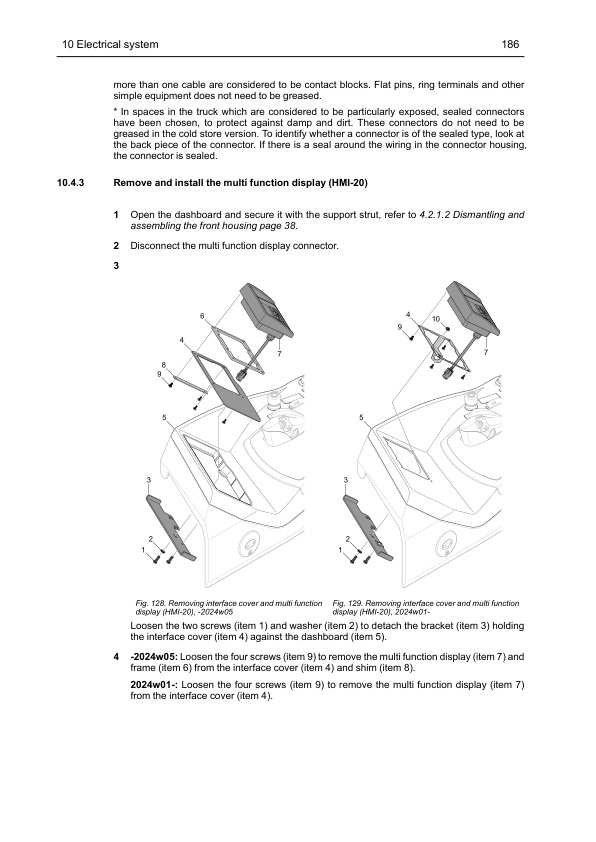
- 10.4.3. Remove and install the multi function display (HMI-20)
- 10.4.4. Remove and install the horn
- 10.4.5. Remove and install the emergency stop
- 10.4.6. Remove and install the direction selector button (option)
- 10.4.7. Remove and install the DC/DC converter (option)
- 10.4.8. Ergologic unit
- 10.4.9. Remove and install the electrical components
- 10.4.10. Traction and pump regulation
- 10.4.11. Insulation resistance
- 10.4.12. Temperature measurement and management
- 10.4.13. System for detecting the reach carriage position
- 10.4.14. Electrical monitoring of battery locking
- 10.4.15. Maintaining and changing the battery (Lead Acid)
- 10.4.16. TruckTool
- 10.5. Diagnostics and troubleshooting
- 11. SPEED CONTROL AND BRAKE SYSTEMS
- 11.1. Design and function
- 11.1.1. Electric brake
- 11.1.2. Speed and brake sensor
- 11.2. Repair and maintenance instructions
- 11.2.1. Electric brakes
- 11.2.2. Brake Pedal Assembly
- 11.2.3. Left-foot switch
- 11.2.4. Speed Controller
- 11.3. Diagnostics and troubleshooting
- 12. MISCELLANEOUS
- 12.1. Options
- 12.1.1. General
- 12.1.2. Service indication
- 12.1.3. Trucks equipped with restart
- 12.1.4. Side shift and tilt centring
- 12.1.5. Speed reduction
- 12.1.6. Automatic logging off
- 12.1.7. Buzzer when the battery voltage is low
- 12.1.8. Hand-controlled direction selector
- 12.1.9. Cold storage cab
- 12.1.10. Battery on motor-powered rollers
- 12.1.11. Electrically heated drivers seat (option)
- 12.2. Level selector and height indication
- 12.2.1. Pulse height preset
- 12.2.2. Level Assistance System, LAS
- 12.2.3. Height indication on the display
- 12.2.4. Checking the fork offset
- 12.3. Stability Support System, S3-1
- 12.3.1. Identification
- 12.3.2. Functionality, S3-1
- 12.3.3. Drive Speed
- 12.3.4. Hydraulic functions
- 12.3.5. Technical description
- 12.4. Weight system
- 12.4.1. Introduction
- 12.4.2. Enable options
- 12.4.3. Accompanying hardware
- 12.4.4. Premises and requirements
- 12.4.5. Calibration of the weight system
- 12.4.6. Weight indication
- 12.5. Load wheel covers
- 12.5.1. Installation of load wheel covers
- 12.6. Delivery mode
- 12.6.1. Driving in delivery mode and platform mode
Related products
-
Mitsubishi PSI 4X LPG Engine Service Manual 99739-7C100
$50.00 Add to cart -
Mitsubishi 4G63, 4G64 Gasoline Engine Service Manual 99729-14110
$50.00 Add to cart -
Mitsubishi 4DQ7, S4S Diesel Engine Service Manual
$50.00 Add to cart -
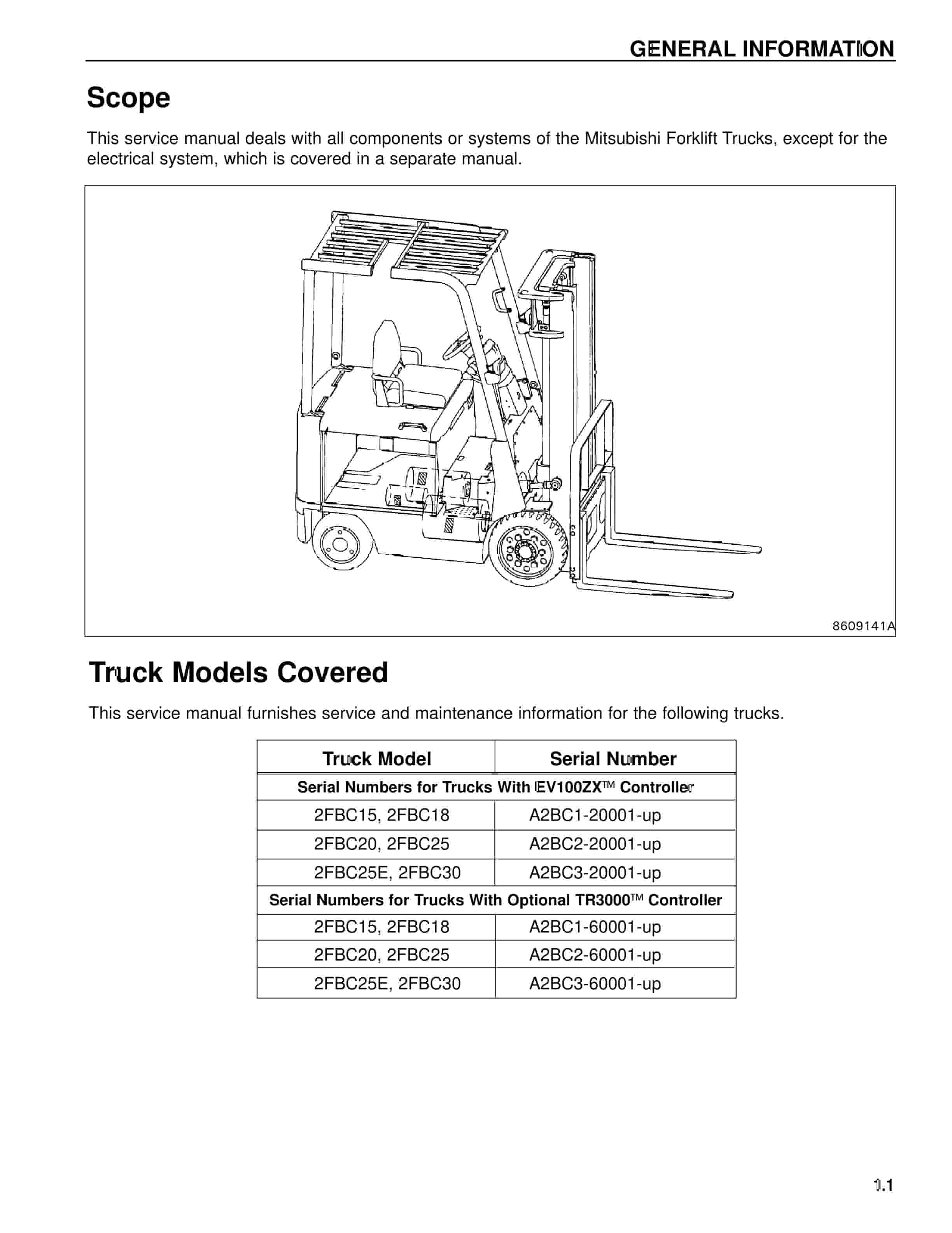
Mitsubishi 2FBC25 Forklift Service Manual
$50.00 Add to cart -
Mitsubishi 4G63, 4G64 Fuel System Supplement Service Manual 99729-75110
$50.00 Add to cart


