

Mitsubishi SBR12N2 to PBS30N2 Service Manual SM24GBST1AA3
$50.00
- Type Of Manual: Service Manual
- Manual ID: SM24GBST1AA3
- Number of Pages: 378
- Size: 19.5MB
- Format: PDF
Product details
-
Model List:
- SBR12N2, SBR12N2I, SBR16N2, SBR16N2I, SBR16N2S, SBR20N2, SBR20N2I, SBR20N2S, SBR10N2TF, PBR20N2, PBR30N2, SBS16N2, SBS16N2I, SBS16N2S, SBS20N2, SBS20N2I, SBS20N2S, SBS10N2TF, PBS20N2, PBS30N2
- 1. GENERAL INFORMATION AND TECHNICAL DATA
- 1.1. Introduction
- 1.1.1. General
- 1.1.2. The trucks
- 1.1.3. Genuine Parts
- 1.1.4. Authorised service personnel
- 1.1.5. Symbol key
- 1.2. Safety
- 1.2.1. General
- 1.2.2. Safety instructions
- 1.2.3. Truck modification
- 1.2.4. Lifting the truck
- 1.2.5. Welding on truck
- 1.3. Environmental considerations
- 1.3.1. We respect the environment
- 1.4. Preparations
- 1.4.1. Service
- 1.4.2. Troubleshooting
- 1.5. Truck data
- 1.5.1. Machine plates
- 1.5.2. Safety and warning signs
- 1.5.3. Type designation
- 1.5.4. Truck types
- 1.5.5. Weight, stand-in stacker version
- 1.5.6. Weight, sit-on stacker version
- 1.5.7. Weight, low lifter
- 1.5.8. Dimensions, stand-in version
- 1.5.9. Dimensions, sit-on version
- 1.5.10. Miscellaneous
- 1.6. Component placement
- 1.7. Component specification
- 1.8. Recommended consumable materials
- 1.8.1. Oil and grease types
- 1.9. Code explanations
- 1.9.1. Colour codes for wiring diagrams
- 1.9.2. Designations for electrical components in electrical diagram
- 1.9.3. Standard abbreviations and units
- 1.9.4. Acronyms and abbreviations
- 2. SPECIAL TOOLS
- 2.1. List of tools
- 3. SERVICE
- 3.1. Service schedule / inspection
- 3.1.1. Introduction
- 3.1.2. Safety
- 3.1.3. Service schedule explanation
- 3.1.4. Inspection daily / monthly / PDI and commissioning
- 3.1.5. First service (200 hours)
- 3.1.6. Main service
- 3.1.7. Extra service inspections
- 3.1.8. Service inspection
- 3.1.9. Dye penetration inspection instruction
- 3.2. Service schedule
- 3.3. Lubrication
- 3.3.1. Recommended lubricants
- 3.3.2. Symbol key, lubrication chart
- 3.3.3. Lubrication chart
- 3.4. Specific instructions
- 3.4.1. Storage of machines and motors
- 3.4.2. Traction motor
- 3.4.3. Gearbox
- 3.4.4. Lift chains and forks
- 3.4.5. Operator protection
- 3.4.6. Hydraulic oil
- 3.5. Maintaining the battery (Lead Acid)
- 3.6. Battery servicing
- 4. CHASSIS
- 4.1. Design and function
- 4.1.1. Machine housing
- 4.1.2. Covers and panels
- 4.1.3. Wheels
- 4.2. Repair and maintenance instructions
- 4.2.1. Before work is performed
- 4.2.2. Remove and install panels and covers
- 4.2.3. Remove and install the overhead guard
- 4.2.4. Remove and install the floor plate, stand-in version
- 4.2.5. Remove and install the floor plate, sit-on version
- 4.2.6. Remove and install the driving seat, sit-on version
- 4.2.7. Wheels
- 5. DRIVE UNIT
- 5.1. Design and function
- 5.1.1. Description
- 5.1.2. Traction Motor
- 5.1.3. Gearbox
- 5.1.4. Drive wheel
- 5.2. Repair and maintenance instructions
- 5.2.1. Before work is performed
- 5.2.2. Servicing and maintenance
- 5.2.3. Traction motor
- 5.2.4. Gearbox
- 5.2.5. Drive wheel
- 5.3. Diagnostics and troubleshooting
- 5.3.1. Troubleshooting chart
- 6. MAST SYSTEM
- 6.1. Design and function
- 6.1.1. Mast systems, Stacker
- 6.1.2. Initial lift (option)
- 6.1.3. Fork carriage, stacker
- 6.1.4. Fork carriage, low lifter
- 6.1.5. Link system
- 6.2. Repair and maintenance instructions
- 6.2.1. Before work is performed
- 6.2.2. Leaning angle of truck, adjustment
- 6.2.3. Initial lift
- 6.2.4. Fork carriage, stacker
- 6.2.5. Fork carriage, low lifter
- 6.2.6. Inspection of welded fork carriages
- 6.2.7. Inspection of forged forks
- 6.2.8. Lift chains
- 6.2.9. Link system
- 6.2.10. Wheels
- 6.2.11. Closed pallet entry and exit (option for low lifter)
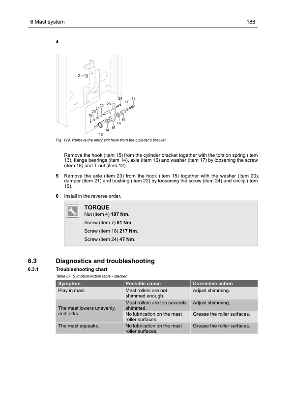
- 6.3. Diagnostics and troubleshooting
- 6.3.1. Troubleshooting chart
- 7. STEERING
- 7.1. Design and function
- 7.1.1. General
- 7.1.2. Feedback sensors
- 7.1.3. Communication between the servo components
- 7.2. Repair and maintenance instructions
- 7.2.1. Before work is performed
- 7.2.2. Remove and install the steering wheel sensor
- 7.2.3. Remove and install the servo motor
- 7.2.4. Remove and install the encoders, servo motor
- 7.2.5. Remove and install the zero position sensor
- 7.2.6. Remove and install the temperature sensor
- 7.2.7. Calibration of the steering angle
- 8. HYDRAULIC SYSTEM
- 8.1. Design and function
- 8.1.1. Description
- 8.1.2. Hose break valve
- 8.1.3. Lowering brake valve
- 8.1.4. Pilot operated check valve
- 8.1.5. Electric proportional valve
- 8.1.6. Hydraulic diagram
- 8.1.7. Hydraulic unit
- 8.1.8. Hydraulic unit valves
- 8.1.9. Hydraulic oil
- 8.2. Repair and maintenance instructions
- 8.2.1. Before work is performed
- 8.2.2. General instructions
- 8.2.3. Installation
- 8.2.4. Connections
- 8.2.5. Hydraulic hoses
- 8.2.6. Start-up
- 8.2.7. Hydraulic oil, changing/draining
- 8.2.8. Replace the air filter, stackers
- 8.2.9. Replace the air filter, low lifters
- 8.2.10. Oil filter element, replacement
- 8.2.11. Checking the hydraulic oil level
- 8.2.12. Hose break valve
- 8.2.13. Hydraulic control valves
- 8.2.14. Hydraulic Pump motor Standard
- 8.2.15. Hydraulic Pump motor Heavy duty
- 8.2.16. Hydraulic pump motor, low lifter
- 8.2.17. Installation instruction for pipe couplings
- 8.3. Diagnostics and troubleshooting
- 8.3.1. Symptom and Actions
- 9. CYLINDERS
- 9.1. Design and function
- 9.1.1. Description
- 9.2. Repair and maintenance instructions
- 9.2.1. Before work is performed
- 9.2.2. Bleeding of the hydraulic cylinders with an air bleed screw
- 9.2.3. Bleeding of the hydraulic cylinders without a bleed air screw
- 9.2.4. Lift cylinder, Triplex with free lift (DTFV)
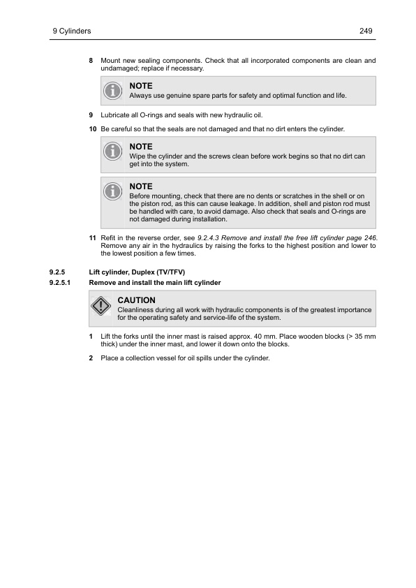
- 9.2.5. Lift cylinder, Duplex (TV/TFV)
- 9.2.6. Lift cylinder, Initial
- 9.2.7. Stabilizer cylinder, Triplex with free lift (DTFV)
- 9.2.8. Lift cylinder, Low lifter
- 10. ELECTRICAL SYSTEM
- 10.1. Introduction
- 10.1.1. Overview of components
- 10.1.2. CAN bus communication
- 10.2. Safety
- 10.2.1. Safety instructions
- 10.2.2. Electronic controllers
- 10.2.3. Sensors
- 10.3. Design and function
- 10.3.1. Battery capacity
- 10.3.2. VCM (Vehicle Control Module) (truck computer)
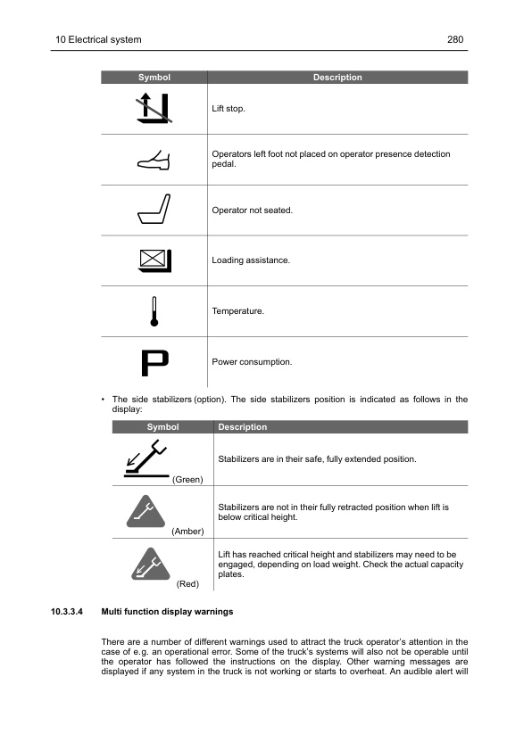
- 10.3.3. Display
- 10.3.4. CMC (Combi Motor Controller)
- 10.3.5. TMC (Traction Motor Controller)
- 10.3.6. PMC (Pump Motor Controller)
- 10.3.7. EPS (Electrical Power Steering) controller
- 10.3.8. Connector specifications
- 10.4. Repair and maintenance instructions
- 10.4.1. Before work is performed
- 10.4.2. Wiring diagram
- 10.4.3. Insulation resistance test
- 10.4.4. Remove and install the battery (Lead Acid)
- 10.4.5. Remove and install the battery (Lithium-ion)
- 10.4.6. Loosen and lift the electric panel, sit-on version
- 10.4.7. Remove and install the CMC
- 10.4.8. Remove and install the TMC
- 10.4.9. Remove and install the PMC
- 10.4.10. Remove and install the EPS
- 10.4.11. Remove and install the control units fan
- 10.4.12. Remove and install the compartment fan, sit-on version
- 10.4.13. Remove and install the VCM
- 10.4.14. Remove and install the relay
- 10.4.15. Remove and install the fuses
- 10.4.16. Remove and install the power fuse
- 10.4.17. Remove and install the EPS Power fuse
- 10.4.18. Remove and install the line contactor
- 10.4.19. Remove and install the emergency stop contactor
- 10.4.20. Remove and install the horn (standard) and buzzer (option)
- 10.4.21. Remove and install the emergency stop
- 10.4.22. Remove and install the standard display (HMI-10)
- 10.4.23. Remove and install the multi function display (HMI-20)
- 10.4.24. Remove and install the DC/DC converter, sit-on version
- 10.4.25. Remove and install the foot protection sensor (option) (S11) reflector, stand-in version
- 10.4.26. Remove and install the safety sensors
- 10.4.27. TruckTool
- 10.5. Diagnostics and troubleshooting
- 11. SPEED CONTROL AND BRAKE SYSTEMS
- 11.1. Design and function
- 11.1.1. Speed control
- 11.1.2. Electric brake
- 11.2. Repair and maintenance instructions
- 11.2.1. Before work is performed
- 11.2.2. Speed Controller
- 11.2.3. Electric brake
- 11.3. Diagnostics and troubleshooting
- 11.3.1. Troubleshoot the speed controller
- 11.3.2. Troubleshoot the brake
- 12. MISCELLANEOUS
- 12.1. Options
- 12.1.1. Additional equipment
- 12.1.2. Equipment bar installation
- 12.1.3. Side posts for overhead guard installation
- 12.1.4. Dashboard protection (only for stand-in version) and mini equipment bar installation
- 12.1.5. Finger guard installation
- 12.1.6. Writing surface installation
- 12.1.7. Rear view mirror installation
- 12.1.8. Work light (option)
- 12.1.9. Interior lights (option)
- 12.1.10. Warning light installation
- 12.1.11. Camera and monitor installation
- 12.1.12. Laser position guide (option)
- 12.1.13. Floor spot (option)
- 12.1.14. Radio (Option)
- 12.1.15. USB-power supply socket (option)
- 12.1.16. power supply socket (option)
- 12.1.17. Direction switch for 360 steering (option)
- 12.1.18. V DC / 12 V DC converter (option)
- 12.1.19. Load backrest (option)
- 12.1.20. Foldable seat (option)
- 12.1.21. Ergo Forks Trailing Control (EFTC) (option)
- 12.1.22. Closed Pallet Entry and Exit (option)
- 12.1.23. Remove and install the side stabilizers
- 12.1.24. Side stabilizer functionality test
- 12.1.25. Side stabilizer adjustment of clearance
- 12.1.26. Travel alarm (option)
Related products
-
Mitsubishi 2FBC25 Forklift Service Manual
$50.00 Add to cart -
Mitsubishi 4G63, 4G64 Gasoline Engine Service Manual 99729-74120
$50.00 Add to cart -
Mitsubishi 4G63, 4G64 Fuel System Supplement Service Manual 99729-75110
$50.00 Add to cart -
Mitsubishi 4G33, 4G52, 4G54 Service Manual 99719-41111
$50.00 Add to cart -
Mitsubishi 1204E Diesel Engine Operation and Maintenance Manual Service Manual 99799-56105
$50.00 Add to cart


