

Caterpillar S6S Diesel Engine Service Manual 99739-32110
$50.00
- Type Of Manual: Service Manual
- Manual ID: 99739-32110
- Number of Pages: 209
- Size: 31.3MB
- Format: PDF
Product details
-
Model List:
- S6S Diesel Engine
- 1.
- 1.1. INTRODUCTION
- 1.1.1. How to use this manual
- 1.1.1.1. Methods of presentation
- 1.1.1.2. Terms used in this manual
- 1.1.1.3. Abbreviations
- 1.1.1.4. Units of measurement
- 1.1.2. Safety Cautions
- 1.1.2.1. Fire and explosion
- 1.1.2.2. Stay clear of all rotating and moving parts
- 1.1.2.3. Be careful of burns
- 1.1.2.4. Be careful of exhaust fume poisoning
- 1.1.2.5. Protect ears from noise
- 1.1.2.6. Be careful of falling down
- 1.1.2.7. Be careful of handling fuel, engine oil and LLC
- 1.1.2.8. Service battery
- 1.1.2.9. When abnormality occurs
- 1.1.2.10. Other cautions
- 1.1.2.11. About warning labels
- 1.1.2.12. Tips on disassembling and assembling
- 1.2. GENERAL CONTENTS
- 1.3. Chapter 1 GENERAL
- 1.4. Chapter 2 SERVICE DATA
- 1.5. Chapter 3 SERVICE TOOLS
- 1.6. Chapter 4 OVERHAUL INSTRUCTIONS
- 1.7. Chapter 5 DISASSEMBLY OF BASIC ENGINE
- 1.8. Chapter 6 INSPECTION AND REPAIR OF BASIC ENGINE
- 1.9. Chapter 7 ASSEMBLY OF BASIC ENGINE
- 1.10. Chapter 8 FUEL SYSTEM
- 1.11. Chapter 9 LUBRICATION SYSTEM
- 1.12. Chapter 10 COOLING SYSTEM
- 1.13. Chapter 11 INLET AND EXHAUST SYSTEMS
- 1.14. Chapter 12 ELECTRICAL SYSTEM
- 1.15. Chapter 13 ADJUSTMENT AND OPERATION
- 1.16. Chapter 1 GENERAL
- 1.16.1. External View
- 1.16.2. System flow diagrams
- 1.16.2.1. Outline of fuel system
- 1.16.2.2. Outline of lubrication system
- 1.16.2.3. Outline of cooling system
- 1.16.2.4. Outline of inlet and exhaust system
- 1.16.3. Engine serial number location
- 1.16.4. Main specifications
- 1.17. Chapter 2 SERVICE DATA
- 1.17.1. Maintenance service data
- 1.17.1.1. Engine general
- 1.17.1.2. Basic engine
- 1.17.1.3. Fuel system
- 1.17.1.4. Lubrication system
- 1.17.1.5. Cooling system
- 1.17.1.6. Inlet and exhaust system
- 1.17.1.7. Electrical system
- 1.17.2. Tightening torque table
- 1.17.2.1. Basic engine
- 1.17.2.2. Fuel system
- 1.17.2.3. Lubrication system
- 1.17.2.4. Cooling system
- 1.17.2.5. Inlet and exhaust system
- 1.17.2.6. Electrical system
- 1.17.2.7. Standard bolt and nut tightening torque
- 1.17.2.8. Standard stud tightening torque
- 1.18. Chapter 3 SERVICE TOOLS
- 1.18.1. Special tools
- 1.19. Chapter 4 OVERHAUL INSTRUCTIONS
- 1.19.1. Determining overhaul timing
- 1.19.2. Compression pressure – Measure
- 1.20. Chapter 5 DISASSEMBLY OF BASIC ENGINE
- 1.20.1. Cylinder heads and Valve mechanisms – Disassemble and Inspect
- 1.20.1.1. Valve clearance – Inspect
- 1.20.1.2. Rocker shaft assembly – Remove
- 1.20.1.3. Cylinder head bolt – Remove
- 1.20.1.4. Cylinder head assembly – Remove
- 1.20.1.5. Valve sinkage – Measure
- 1.20.1.6. Valve and Valve spring – Remove
- 1.20.2. Rear equipment – Disassemble and Inspect
- 1.20.2.1. Flywheel face and radial runouts – Measure
- 1.20.2.2. Flywheel – Remove
- 1.20.2.3. Rear plate – Remove
- 1.20.3. Front equipment – Disassemble and Inspect
- 1.20.3.1. Damper face and radial runouts – Measure
- 1.20.3.2. Damper and Crankshaft pulley – Remove
- 1.20.3.3. Timing gear case – Remove
- 1.20.3.4. Timing gear backlash – Measure
- 1.20.3.5. Idler gear and camshaft end play – Measure
- 1.20.3.6. Fuel injection pump – Remove
- 1.20.3.7. Oil pan – Remove
- 1.20.3.8. Oil strainer – Remove
- 1.20.3.9. Oil pump gear – Remove
- 1.20.3.10. Idler gear – Remove
- 1.20.3.11. Camshaft – Remove
- 1.20.3.12. Camshaft gear – Replace
- 1.20.3.13. Front plate – Remove
- 1.20.3.14. Oil pump – Remove
- 1.20.4. Piston, Connecting rod, Crankshaft and Crankcase – Disassemble and Inspect
- 1.20.4.1. Piston protrusion – Measure
- 1.20.4.2. Carbon deposits from the upper part of cylinder – Remove
- 1.20.4.3. End play of connecting rod big end – Measure
- 1.20.4.4. Connecting rod cap – Remove
- 1.20.4.5. Piston – Remove
- 1.20.4.6. Piston ring – Remove
- 1.20.4.7. Piston pin and Piston – Remove
- 1.20.4.8. Crankshaft end play – Measure
- 1.20.4.9. Main bearing cap – Remove
- 1.20.4.10. Crankshaft – Remove
- 1.20.4.11. Tappet – Remove
- 1.21. Chapter 6 INSPECTION AND REPAIR OF BASIC ENGINE
- 1.21.1. Cylinder head and Valve mechanism – Inspect and Repair
- 1.21.1.1. Clearance between rocker bushing and rocker shaft – Measure
- 1.21.1.2. Valve stem outside diameter and Valve guide inside diameter – Measure
- 1.21.1.3. Valve guide – Replace
- 1.21.1.4. Valve face – Inspect
- 1.21.1.5. Valve face – Reface
- 1.21.1.6. Valve seat – Reface
- 1.21.1.7. Valve seat – Replace
- 1.21.1.8. Valve and Valve seat – Lap
- 1.21.1.9. Squareness and free length of valve spring – Measure
- 1.21.1.10. Pushrod runout – Measure
- 1.21.1.11. Distortion of cylinder head bottom surface – Measure
- 1.21.1.12. Combustion jet – Replace
- 1.21.2. Rear equipment – Inspect and Repair
- 1.21.2.1. Flatness of flywheel – Measure
- 1.21.2.2. Ring gear – Inspect
- 1.21.2.3. Ring gear – Replace
- 1.21.3. Front equipment – Inspect and Repair
- 1.21.3.1. Damper – Inspect visually
- 1.21.3.2. Idler bushing inside diameter and Idler shaft outside diameter – Measure
- 1.21.3.3. Idler shaft – Replace
- 1.21.3.4. Cam lift of camshaft – Measure
- 1.21.3.5. Camshaft runout – Measure
- 1.21.3.6. Camshaft journal outside diameter – Measure
- 1.21.3.7. Camshaft hole (bushing) inside diameter – Measure
- 1.21.3.8. Camshaft bushing – Replace
- 1.21.3.9. V-belt groove wear – Inspect
- 1.21.4. Piston and Connecting rod – Inspect and Repair
- 1.21.4.1. Piston – Inspect visually
- 1.21.4.2. Piston outside diameter – Measure
- 1.21.4.3. Piston ring groove – Inspect
- 1.21.4.4. Piston pin bore diameter and Piston pin outside diameter – Measure
- 1.21.4.5. Standard for piston ring replacement
- 1.21.4.6. Clearance between connecting rod bearing and crankpin – Measure
- 1.21.4.7. Clearance between connecting rod bushing and piston pin – Measure
- 1.21.4.8. Connecting rod bushing – Replace
- 1.21.4.9. Weight difference of connecting rod assembly in one engine
- 1.21.4.10. Connecting rod bearing – Inspect
- 1.21.4.11. Connecting rod bend and twist – Inspect
- 1.21.5. Crankcase and Crankshaft – Inspect and Repair
- 1.21.5.1. Cylinder inside diameter – Measure
- 1.21.5.2. Crankcase top surface distortion – Measure
- 1.21.5.3. Crankpin and Crank journal outside diameters – Measure
- 1.21.5.4. Crankpin and journal width – Measure
- 1.21.5.5. Crankshaft – Grind
- 1.21.5.6. Crankshaft runout – Measure
- 1.21.5.7. Crankshaft gear – Inspect
- 1.21.5.8. Crankshaft gear – Replace
- 1.21.5.9. Oil seal contact surface – Inspect
- 1.21.5.10. Oil seal sleeve – Install
- 1.21.5.11. Oil seal sleeve – Remove
- 1.21.5.12. Main bearing – Inspect
- 1.21.5.13. Clearance between main bearing and crank journal – Measure
- 1.21.5.14. Thrust plate – Inspect
- 1.21.5.15. Tappet – Inspect
- 1.22. Chapter 7 ASSEMBLY OF BASIC ENGINE
- 1.22.1. Piston, Connecting rod, Crankshaft and Crankcase – Assemble
- 1.22.1.1. Crankcase – Invert
- 1.22.1.2. Tappet – Install
- 1.22.1.3. Upper main bearing – Install
- 1.22.1.4. Rear upper thrust plate – Install
- 1.22.1.5. Crankshaft – Install
- 1.22.1.6. Lower main bearing and Lower thrust plate – Install
- 1.22.1.7. Main bearing cap – Install
- 1.22.1.8. Crankshaft end play – Measure
- 1.22.1.9. Side seal – Insert
- 1.22.1.10. Piston and Connecting rod – Assemble
- 1.22.1.11. Piston ring – Install
- 1.22.1.12. Piston installation – Prepare
- 1.22.1.13. Connecting rod bolt and Upper connecting rod bearing – Install
- 1.22.1.14. Piston – Install
- 1.22.1.15. Connecting rod cap – Install
- 1.22.1.16. End play of connecting rod big end – Measure
- 1.22.1.17. Piston protrusion – Measure
- 1.22.2. Front equipment – Assemble
- 1.22.2.1. Oil pump – Install
- 1.22.2.2. Front plate – Install
- 1.22.2.3. Camshaft – Install
- 1.22.2.4. Idler gear – Install
- 1.22.2.5. Oil pump gear – Install
- 1.22.2.6. Fuel injection pump – Install
- 1.22.2.7. Timing gear backlash – Measure
- 1.22.2.8. Idler gear end play – Measure
- 1.22.2.9. Camshaft end play – Measure
- 1.22.2.10. Front oil seal – Install
- 1.22.2.11. Timing gear case – Install
- 1.22.2.12. Oil strainer – Install
- 1.22.2.13. Oil pan – Install
- 1.22.2.14. Crankcase – Invert
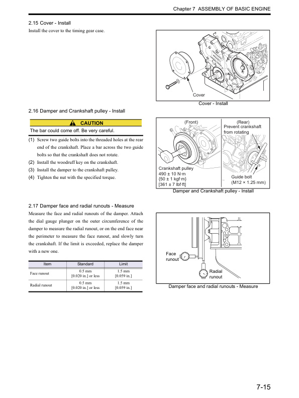
- 1.22.2.15. Cover – Install
- 1.22.2.16. Damper and Crankshaft pulley – Install
- 1.22.2.17. Damper face and radial runouts – Measure
- 1.22.3. Rear equipment – Assemble
- 1.22.3.1. Rear oil seal – Install
- 1.22.3.2. Rear plate – Install
- 1.22.3.3. Flywheel – Install
- 1.22.3.4. Flywheel face and radial runouts – Measure
- 1.22.4. Cylinder head and Valve mechanism – Assemble
- 1.22.4.1. Cylinder head – Assemble
- 1.22.4.2. Valve sinkage – Measure
- 1.22.4.3. Cylinder head gasket – Install
- 1.22.4.4. Cylinder head assembly – Install
- 1.22.4.5. Cylinder head bolt – Tighten
- 1.22.4.6. Push rod – Insert
- 1.22.4.7. Rocker shaft assembly – Install
- 1.22.4.8. Valve clearance – Inspect and Adjust
- 1.22.4.9. Rocker cover – Install
- 1.23. Chapter 8 FUEL SYSTEM
- 1.23.1. Fuel system – Remove
- 1.23.2. Fuel system – Disassemble, Inspect and Assemble
- 1.23.2.1. Fuel filter – Disassemble, Inspect and Assemble
- 1.23.2.2. Fuel filter – Assemble
- 1.23.2.3. Fuel injection nozzle – Disassemble and Inspect
- 1.23.2.4. Fuel injection nozzle – Inspect and Adjust
- 1.23.2.5. Fuel injection nozzle – Assemble
- 1.23.2.6. Gauze filter of distribute type fuel injection pump – Inspect and Clean
- 1.23.3. Fuel system – Install
- 1.24. Chapter 9 LUBRICATION SYSTEM
- 1.24.1. Lubrication system – Remove
- 1.24.2. Lubrication system – Disassemble, Inspect and Assemble
- 1.24.2.1. Oil pump – Disassemble and Inspect
- 1.24.2.2. Oil pump – Inspect
- 1.24.2.3. Oil pump – Assemble
- 1.24.2.4. Oil filter – Inspect
- 1.24.2.5. Relief valve – Inspect
- 1.24.3. Lubrication system – Install
- 1.25. Chapter 10 COOLING SYSTEM
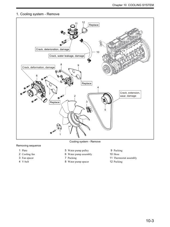
- 1.25.1. Cooling system – Remove
- 1.25.2. Cooling system – Disassemble, Inspect and Assemble
- 1.25.2.1. Thermostat – Disassemble and Inspect
- 1.25.2.2. Thermostat – Inspect
- 1.25.2.3. Water pump – Disassemble and Inspect
- 1.25.3. Cooling system – Install
- 1.26. Chapter 11 INLET AND EXHAUST SYSTEMS
- 1.26.1. Inlet and exhaust systems – Remove
- 1.26.2. Inlet and exhaust systems – Disassemble, Inspect and Assemble
- 1.26.2.1. Exhaust manifold distortion – Measure
- 1.26.3. Inlet and exhaust systems – Install
- 1.27. Chapter 12 ELECTRICAL SYSTEM
- 1.27.1. Electrical system – Remove and Inspect
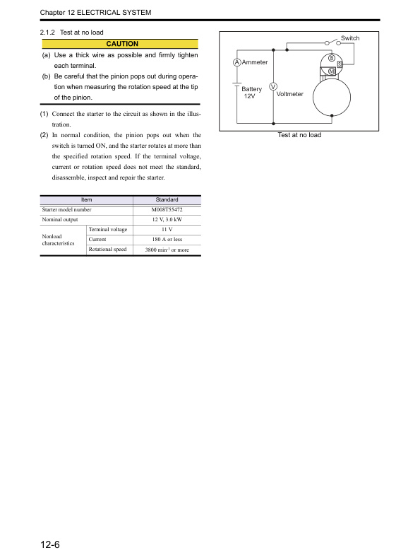
- 1.27.1.1. Starter – Remove and Inspect
- 1.27.1.2. Inspection before removal of alternator
- 1.27.1.3. Alternator – Remove and Inspect
- 1.27.1.4. Magnetic valve (stop solenoid) – Remove and Inspect
- 1.27.1.5. Glow plug – Remove and Inspect
- 1.27.2. Electrical system – Disassemble, Inspect and Assemble
- 1.27.2.1. Inspection before disassembling starter
- 1.27.2.2. Starter – Disassemble and Inspect
- 1.27.2.3. Starter – Inspect and Repair
- 1.27.2.4. Starter – Assemble
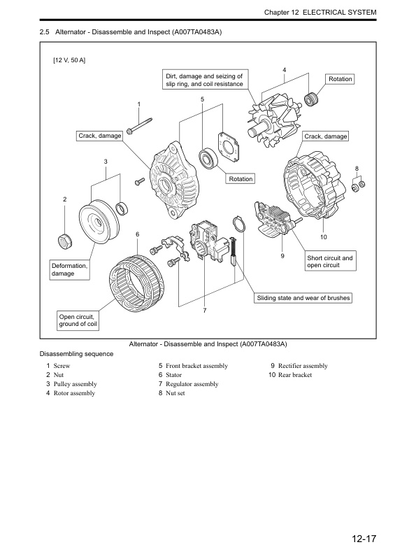
- 1.27.2.5. Alternator – Disassemble and Inspect (A007TA0483A)
- 1.27.2.6. Alternator – Inspect and Repair (A007TA0483A)
- 1.27.2.7. Alternator – Assemble (A007TA0483A)
- 1.27.2.8. Alternator – Disassemble and Inspect (A005TA5083A)
- 1.27.2.9. Alternator – Inspect and Repair (A005TA5083A)
- 1.27.2.10. Alternator – Assemble (A005TA5083A)
- 1.27.2.11. Alternator – Disassemble and Inspect (A002TA7871)
- 1.27.2.12. Alternator – Inspect and Repair (A002TA7871)
- 1.27.2.13. Alternator – Assemble (A002TA7871)
- 1.27.2.14. Glow plug – Inspect and Repair
- 1.27.2.15. Magnetic valve (stop solenoid) – Inspect and Repair
- 1.27.3. Electrical system – Install
- 1.27.3.1. Glow plug – Install
- 1.27.3.2. Magnetic valve (stop solenoid) – Install
- 1.27.3.3. Alternator – Install
- 1.27.3.4. Starter – Install
- 1.28. Chapter 13 ADJUSTMENT AND OPERATION
- 1.28.1. Engine – Adjust
- 1.28.1.1. Valve clearance – Inspect
- 1.28.1.2. Fuel system – Drain
- 1.28.1.3. Fuel system – Bleed air
- 1.28.1.4. V-belt tension – Inspect and Adjust
- 1.28.2. Break-in operation
- 1.28.2.1. Starting up
- 1.28.2.2. Break-in operation
- 1.28.3. Performance test
- 1.28.3.1. Engine equipment condition
- 1.28.3.2. Test items and purposes
- 1.28.3.3. Other inspections
- 1.28.3.4. Engine output adjustment
- 1.29. TECHNICAL PUBLICATIONS FEEDBACK
- 1.30. Back cover
- 1.31. Rear cover
- 2.
- 2.1. INTRODUCTION
- 2.1.1. How to use this manual
- 2.1.1.1. Methods of presentation
- 2.1.1.2. Terms used in this manual
- 2.1.1.3. Abbreviations
- 2.1.1.4. Units of measurement
- 2.1.2. Safety Cautions
- 2.1.2.1. Fire and explosion
- 2.1.2.2. Stay clear of all rotating and moving parts
- 2.1.2.3. Be careful of burns
- 2.1.2.4. Be careful of exhaust fume poisoning
- 2.1.2.5. Protect ears from noise
- 2.1.2.6. Be careful of falling down
- 2.1.2.7. Be careful of handling fuel, engine oil and LLC
- 2.1.2.8. Service battery
- 2.1.2.9. When abnormality occurs
- 2.1.2.10. Other cautions
- 2.1.2.11. About warning labels
- 2.1.2.12. Tips on disassembling and assembling
- 2.2. GENERAL CONTENTS
- 2.3. Chapter 1 GENERAL
- 2.4. Chapter 2 SERVICE DATA
Related products
-
Caterpillar 2EC15-30 Chassis and Mast Service Manual 99759-80100
$50.00 Add to cart -
Caterpillar 4G63, 4G64, 6G72 Liquefied Petroleum Gas Supplement Service Manual 99729-85100
$50.00 Add to cart -
Caterpillar 1.4 Liter (4G33) to 3.0 Liter (6G72) LP Gas Supplement Service Manual SENB8531
$50.00 Add to cart -

Caterpillar 2EC15 to 2EC30 MicroCommand II Control Service Manual SENB8609
$50.00 Add to cart -

Caterpillar 1204F Diesel Engine Systems Operation Testing and Adjusting Service Manual 99799-67103
$50.00 Add to cart


%20to%203.0%20Liter%20(6G72)%20LP%20Gas%20Supplement%20Service%20Manual%20SENB8531&url=https://ownersmanualpdf.net/docs/caterpillar-1-4-liter-4g33-to-3-0-liter-6g72-lp-gas-supplement-service-manual-senb8531/&media=https://ownersmanualpdf.net/wp-content/uploads/2025/10/caterpillar-14-liter-4g33-to-30-liter-6g72-lp-gas-supplement-service-manual-senb8531-1.jpg)

