

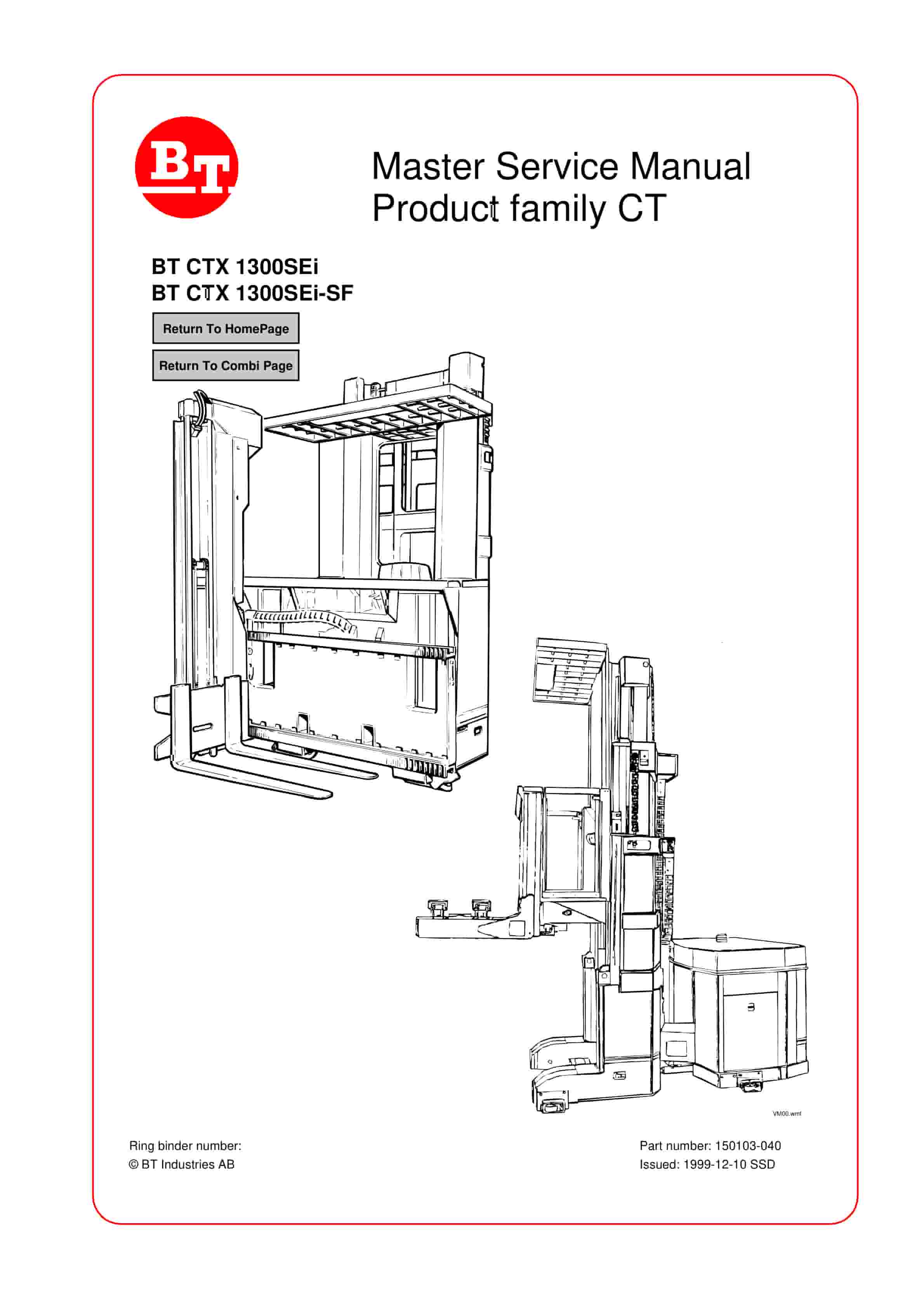
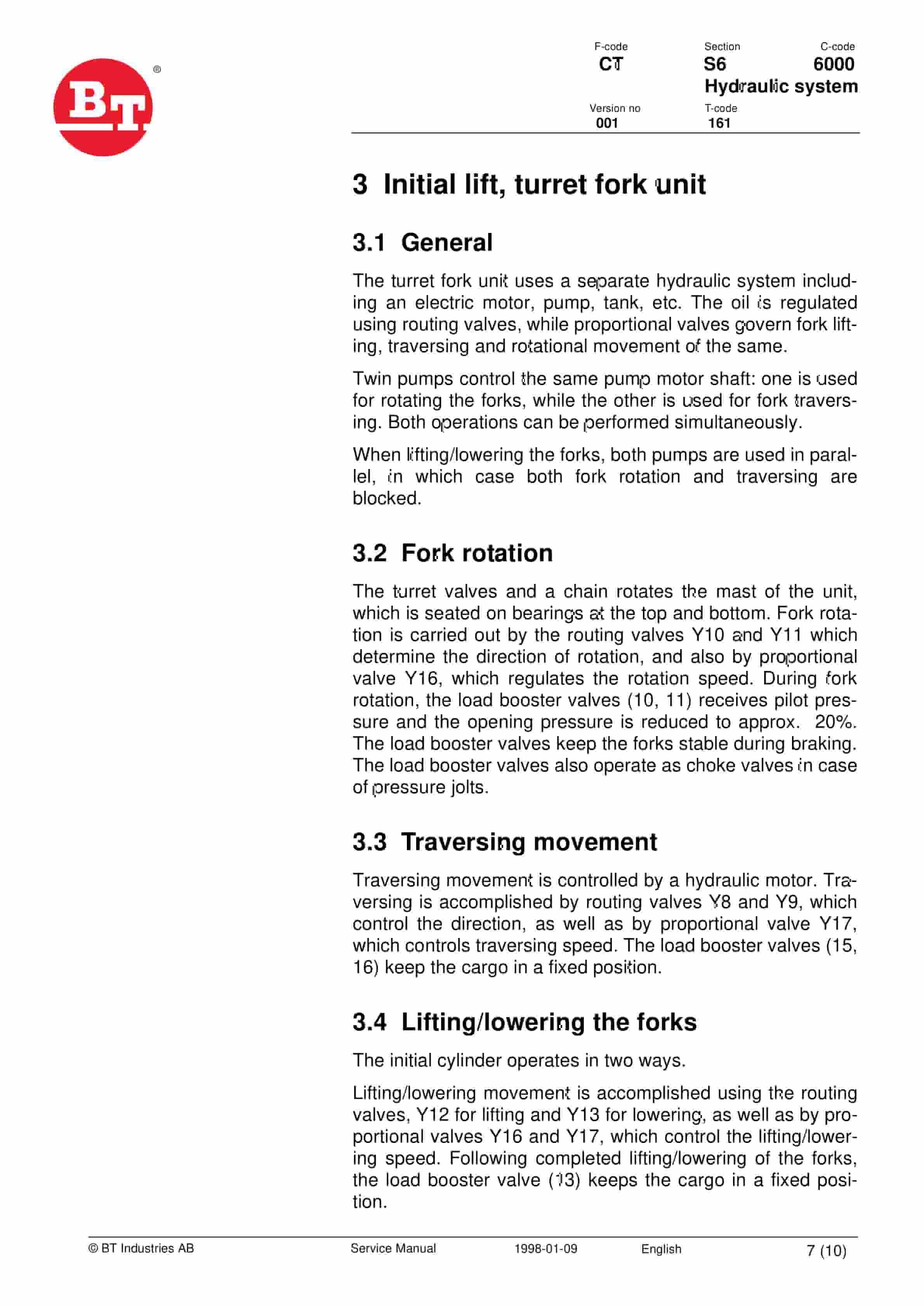
BT CTX 1300SEi, CTX 1300SEi SF Service Manual 150103-040
$30.00
- Type Of Manual: Service Manual
- Manual ID: 150103-040
- : Service Manual PDF
- Number of Pages: 300
- Size: 7.8MB
- Format: PDF
Product details
-
Model List:
- CTX 1300SEi, CTX 1300SEi SF
- 1. Return to Home Page
- 2. Master Service Manual Product family CT
- 2.1. BT CTX 1300SEi BT CTX 1300SEi-SF
- 3. Contents Master Service Manual (MSM)
- 3.1. Valid from serial number
- 3.1.1. Serial No
- 3.2. Document list
- 3.2.1. Section
- 3.2.2. Document
- 4. Introduction to BTs Service Manual
- 5. Contents, M
- 5.1. Truck information
- 6. Operators manual
- 6.1. Valid from serial number
- 6.2. Serial No
- 6.3. General
- 6.3.1. Issued operators manuals
- 7. General product information
- 7.1. Valid from serial number
- 7.1.1. Serial No
- 7.2. Presentation of the truck
- 7.2.1. Intended application of the truck
- 7.2.2. Forbidden application of the truck
- 7.3. Truck data
- 7.3.1. Model designation
- 7.3.2. CTX 1300SEi (Fork skew)
- 7.3.3. CTX H (Fork skew)
- 7.3.4. Model designation
- 7.3.5. CTX 1300 SEi SF (tele fork)
- 7.3.6. CTX H SF (tele fork)
- 7.4. Truck dimensions
- 7.4.1. Dimensions CTX 1300SEi
- 7.4.2. Dimensions CTX 1300SEi SF
- 7.4.3. CTX H SF
- 7.5. Identification plate
- 7.6. Main components
- 7.6.1. Identification plate With model designation, serial number, year of manufacture, weight witho…
- 7.6.2. Mast
- 7.6.3. Emergency switch off
- 7.6.4. Emergency lowering valve Valve for emergency lowering under the guard.
- 7.6.5. Load carrier
- 7.6.6. Initial lift mast
- 7.6.7. Identification plate With model designation, serial number, year of manufacture, weight witho…
- 7.6.8. Mast
- 7.6.9. Emergency switch off
- 7.6.10. Emergency lowering valve Valve for emergency lowering under the guard.
- 7.6.11. Load carrier
- 7.6.12. Initial lift mast
- 7.7. Warning and information plates and symbols
- 7.7.1. Attachment point for spring-loaded hooks
- 7.7.2. Passengers prohibited
- 7.7.3. Identification plate
- 7.7.4. Joystick functions right
- 7.7.5. Joystick functions left
- 7.7.6. Do not walk under an elevated load
- 7.7.7. Emergency lower
- 7.7.8. Hydraulic oil filling
- 7.7.9. Risk of crushing
- 7.7.10. Lifting points
- 7.7.11. Attachment point for spring-loaded hooks
- 7.7.12. Passengers prohibited
- 7.7.13. Identification plate
- 7.7.14. Joystick functions right
- 7.7.15. Joystick functions left
- 7.7.16. Do not walk under an elevated load
- 7.7.17. Emergency lower
- 7.7.18. Hydraulic oil filling
- 7.7.19. Risk of crushing
- 7.7.20. Lifting points
- 8. Technical data
- 8.1. Valid from serial number
- 8.2. Serial No.
- 8.3. CTX 1300SEi
- 8.4. CTX 1300SEi-SF
- 8.4.1. Drive motor
- 8.4.2. Transmission/gear
- 8.4.3. Drive wheel
- 8.4.4. Support arm wheels
- 8.4.5. Hydraulic system, drive unit
- 8.4.6. Hydraulic system, fork unit
- 8.4.7. Batteries
- 8.4.8. All models
- 8.4.9. Travel speeds
- 8.4.10. Lifting/lowering speeds
- 8.4.11. Other speeds (unit speeds)
- 8.4.12. Power consumption
- 9. Ordering Spare Parts
- 10. Quality Parts
- 10.1. Valid from serial number
- 10.2. Serial No
- 10.3. Issued Quality Parts
- 10.3.1. Serial No
- 10.3.2. Order number
- 11. Recommended Spare Parts (RSP)
- 11.1. Valid from serial number
- 11.2. Serial No
- 11.3. Issued RSP
- 11.3.1. Serial No
- 12. Contents, P
- 12.1. Preventive Maintenance
- 13. Introduction, maintenance
- 13.1. Safety regulations with maintenance work
- 13.1.1. WARNING
- 13.1.2. WARNING
- 13.1.3. WARNING
- 13.1.4. CAUTION
- 13.2. Cleaning and washing
- 13.2.1. External cleaning
- 13.2.2. Cleaning the motor compartment
- 13.2.3. Electrical components
- 13.3. Safe lifting
- 13.3.1. WARNING
- 14. Preventive Maintenance
- 14.1. Valid from serial number
- 14.2. Serial No.
- 14.3. Maintenance Chart
- 14.3.1. Work to carry out
- 15. Preventive Maintenance
- 15.1. Valid from serial number
- 15.2. Serial No
- 15.3. Maintenance Chart
- 15.3.1. Work to carry out
- 16. Oil and Grease Specification
- 16.1. Valid from serial number
- 16.2. Serial No.
- 16.3. Lubricant
- 16.4. Specification
- 17. Contents, S
- 17.1. Service instructions
- 18. Chassis
- 18.1. Valid from serial number
- 18.2. Serial No.
- 18.3. General
- 18.3.1. Lifting using lifting hooks or wires
- 18.3.2. Lifting using a forklift
- 18.4. BT CTX with dismantled mast
- 18.4.1. General
- 18.4.2. Mounting the mast on the chassis
- 19. Drive unit/gear
- 19.1. Valid from serial number
- 19.2. Serial Nr
- 19.3. General
- 19.4. Gear components/data
- 19.4.1. Component identification
- 19.4.2. Technical gear data
- 19.4.3. Dismantled gear
- 19.5. Dismantling/fitting
- 19.5.1. Dismantling of drive unit from truck
- 19.5.2. Fitting the drive unit in truck
- 19.5.3. Dismantling the drive motor and the gear
- 19.5.4. Fitting the drive motor and the gear
- 19.6. Oil level check/replacing
- 19.6.1. Check/filling of oil
- 19.6.2. Oil replacement
- 19.7. Repairs
- 19.7.1. Exchange of drive shaft sealing ring
- 19.7.2. Leakage from the top cover
- 19.7.3. Leakage from the lower cover
- 19.7.4. Replacing the wheel bolt
- 20. Drive unit/gear
- 20.1. Valid from serial number
- 20.2. Serial No.
- 20.3. General
- 20.4. Components/data of the drive unit and gear
- 20.4.1. Component identification
- 20.4.2. Technical data
- 20.4.3. Dismantled gear
- 20.5. Replacing the drive motor/drive gear
- 20.5.1. Dismantling of drive unit from truck
- 20.5.2. Fitting the drive unit in truck
- 20.5.3. Dismantling the drive motor and the gear
- 20.5.4. Fitting the drive motor and the gear
- 20.6. Oil level check/replacement
- 20.6.1. Checking/filling of oil
- 20.6.2. Oil replacement
- 20.7. Repairs
- 20.7.1. Replacing the drive shaft sealing ring
- 20.7.2. Leakage from the top cover
- 20.7.3. Leakage from the lower cover
- 20.7.4. Replacing the wheel bolt
- 21. Magnetic brake
- 21.1. Valid from serial number
- 21.2. Serial No.
- 21.3. General
- 21.3.1. Function
- 21.4. Maintenance
- 21.4.1. Adjustment
- 21.4.2. Replacing the brake disc
- 22. Wire guidance
- 22.1. Valid from serial number
- 22.2. Serial No.
- 22.3. General
- 22.4. Generator
- 22.4.1. Technical data
- 22.5. Antennas
- 22.5.1. Antenna cable
- 22.6. Wire guidance logic card
- 22.6.1. Components
- 22.6.2. Connectors
- 22.6.3. Display
- 22.7. Miscellaneous
- 22.8. Description of function
- 22.8.1. Forward travel
- 22.8.2. Reverse travel
- 22.8.3. Control signals
- 22.9. Adjustments
- 22.9.1. Truck computer A2
- 22.9.2. Wire guidance logic card A3
- 22.10. Installing a new wire guidance logic card
- 22.10.1. Truck model
- 22.10.2. ID number
- 22.10.3. Truck model
- 22.10.4. ID number
- 22.11. Troubleshooting
- 22.11.1. Control signals
- 22.12. Electrical System
- 22.12.1. Valid from serial number
- 22.12.2. Serial No.
- 22.12.3. General
- 23. Electric panel on chassis
- 24. Electrical panel, operators cabin
- 25. General description of the electrical system
- 25.1. Drive motor circuit (sheet 1)
- 25.2. Pump, cabin lift, battery indicator/hour counter (sheet 2)
- 25.3. Inputs to logic card A2 (sheet 3)
- 25.4. Inputs to logic card A2 (sheet 4)
- 25.5. Inputs to logic card A2 (sheet 5)
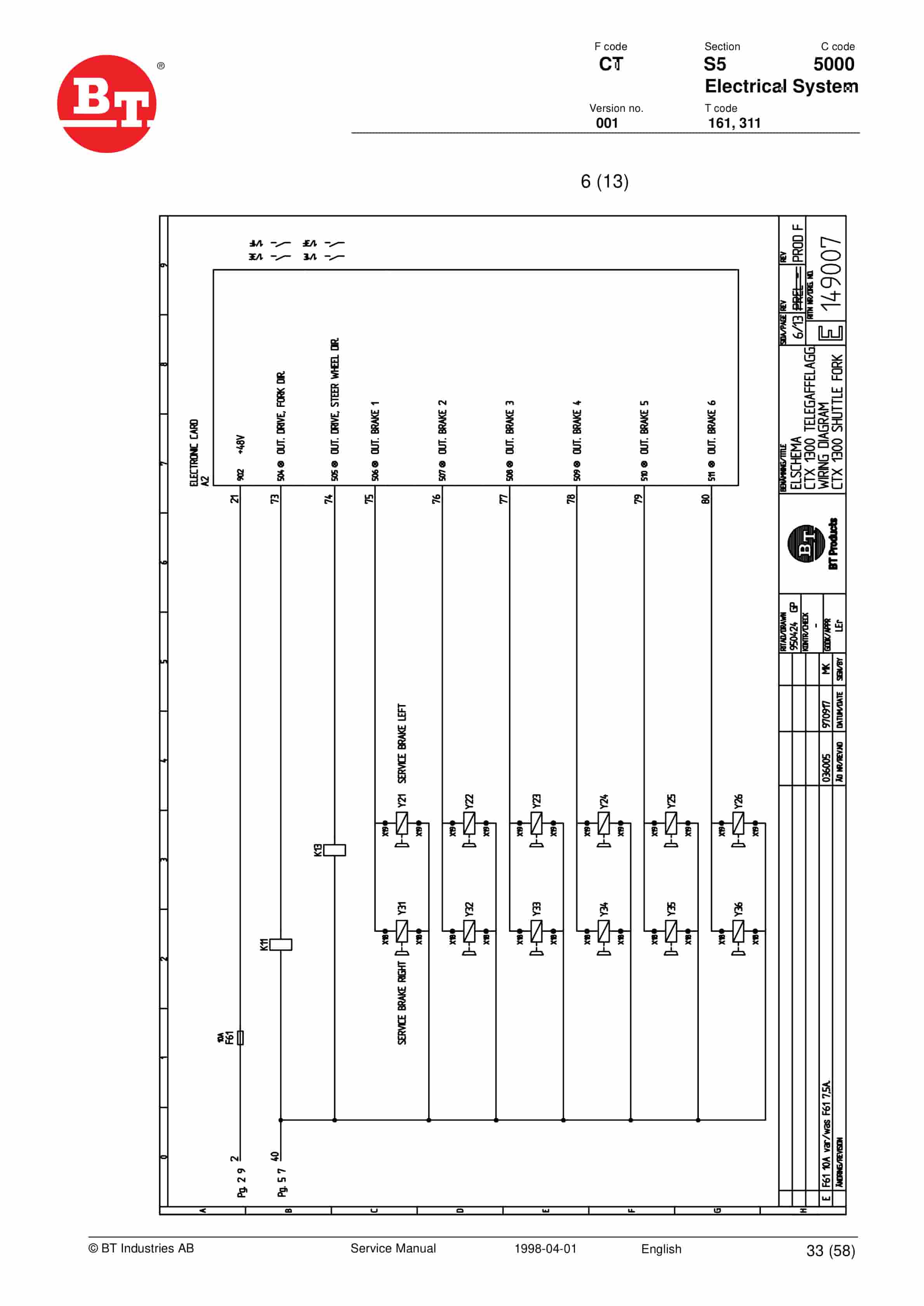
- 25.6. Outputs from logic card A2 (sheet 6)
- 25.7. Outputs from logic card A2 (sheet 7)
- 25.8. Outputs from logic card A2 (sheet 8)
- 25.9. Horn, lighting, and fork pump motor (sheet 9)
- 25.10. Inputs to the logic card A4 (sheet 10)
- 25.11. Outputs from the logic card A4 (sheet 10)
- 25.12. Inputs to the logic card A4 (sheet 11)
- 25.13. Outputs from the logic card A4 (sheet 11)
- 25.14. Outputs from the logic card A4 (sheet 12)
- 25.15. Wire guidance (sheet 13)
- 25.16. List of symbols and circuit diagrams
- 26. Symbol list
- 26.1. Description
- 27. Electrical diagrams T code 161
- 28. Electrical diagrams T code 311
- 29. Component list
- 29.1. Description
- 29.2. Designation – Function
- 29.3. Description of function
- 30. Start
- 31. Presence control
- 31.1. Open cabin gates
- 31.2. Closed cabin gates
- 32. Dead mans handle
- 33. Forward/Reverse travel
- 34. Emergency drive position
- 35. Travel speed
- 35.1. Out of aisle
- 35.2. In narrow aisles, rail steering
- 35.3. In narrow aisles, wire guidance
- 36. Braking
- 37. End-of-aisle brake
- 38. Steering
- 39. Lifting the cabin
- 40. Lowering the cabin
- 41. Slack chain guard
- 42. Turret head fork unit
- 42.1. Traversing
- 42.2. Rotation
- 42.3. Lifting/lowering the forks
- 42.4. Extra function
- 42.5. Miscellaneous
- 43. Shuttle Fork Unit
- 43.1. Right dead mans handle not engaged.
- 43.2. Joystick not centered.
- 43.3. Right dead mans handle engaged.
- 43.4. Forks moving left or right.
- 43.5. Forks moving up or down.
- 43.6. Computer error at start-up.
- 43.7. Safety relay malfunction.
- 43.8. Short-circuit on one of the outputs.
- 43.9. Side-shift
- 43.10. Lifting/lowering the forks
- 43.11. Miscellaneous
- 44. Miscellaneous
- 44.1. Adjustments
- 45. Speed sensors (S55, S56)
- 46. Traversing sensors (S57, S58)
- 47. Height sensor (S90-S92, S104-S106)
- 48. Display
- 48.1. Valid from serial number
- 48.2. Serial No.
- 48.3. Display indications and pushbuttons
- 48.3.1. Indication Truck OK The green LED comes on when the truck is ready for use.
- 48.3.2. Indication Straight articulated centre The green LED comes on when the truck is perfectly s…
- 48.3.3. Indication Truck in aisle The green LED comes on when the truck is in a narrow aisle.
- 48.3.4. Indication Wire guidance The yellow LED blinks when the truck is searching for the wire and…
- 48.3.5. Indication Forks not in home position The red LED lights when the forks are not in the hom…
- 48.3.6. Indication Open gate The red LED lights when the gate has not been closed and the right joy…
- 48.3.7. Indication Slack chain The red LED lights when there is slack in one of the cabin lifting c…
- 48.3.8. Indication Battery status The red LED lights when there is no more than 20 left of the bat…
- 48.3.9. Enter button Pushbutton used to store parameters.
- 48.3.10. /- button Pushbutton used to change parameter values.
- 48.3.11. Up/Down button Pushbutton used to select parameters.
- 48.4. Display menus
- 48.4.1. Normal position
- 48.4.2. Emergency drive position
- 48.4.3. Programming position
- 49. Transistor regulator
- 49.1. Valid from serial number
- 49.2. Serial No.
- 49.3. Transistor regulator
- 49.3.1. Motor Connections
- 49.3.2. Control voltage contact
- 49.4. Technical data
- 49.5. LED indications
- 49.5.1. LED No.
- 49.5.2. Indicates
- 49.5.3. Diagnosis
- 49.6. Maintenance
- 49.6.1. Safety
- 49.6.2. Cleaning
- 49.7. Safety inspection
- 49.7.1. Check transistor regulator safety circuit
- 50. Electronic card A2
- 50.1. Valid from serial number
- 50.2. Serial No.
- 50.3. General
- 50.4. A2 connection terminals and voltages
- 50.4.1. X91
- 50.4.2. X92
- 50.4.3. X93
- 50.4.4. X94
- 50.4.5. X95
- 50.4.6. X96
- 50.4.7. X97
- 50.4.8. X98
- 50.4.9. X99
- 50.5. A2 board adjustments
- 50.5.1. Adjustment of steering centre position
- 50.5.2. Adjustment of cabin lift (offset)
- 50.5.3. Adjustment of cabin lowering (offset)
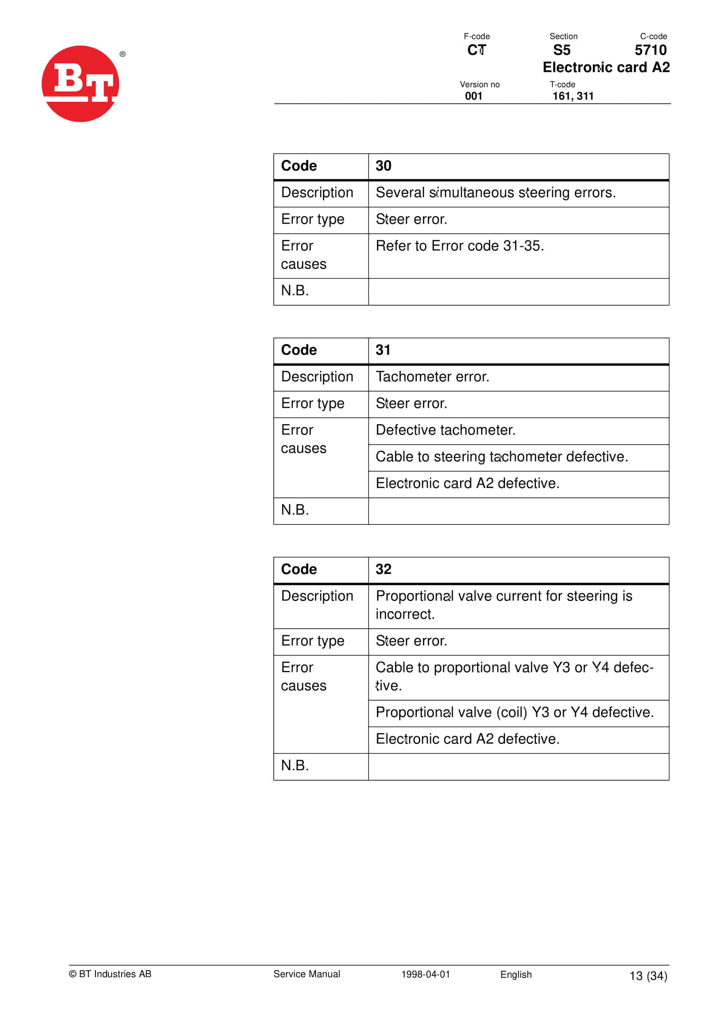
- 50.6. Error codes
- 50.6.1. Error types
- 50.6.2. Error codes
- 50.6.3. Installing a new board in the truck
- 50.6.4. Programming parameters
- 51. Electronic card
- 51.1. Valid from serial number
- 51.2. Serial No.
- 51.3. General
- 51.4. Connection terminals and voltages on A4
- 51.4.1. A4100
- 51.4.2. A4200
- 51.4.3. A4300
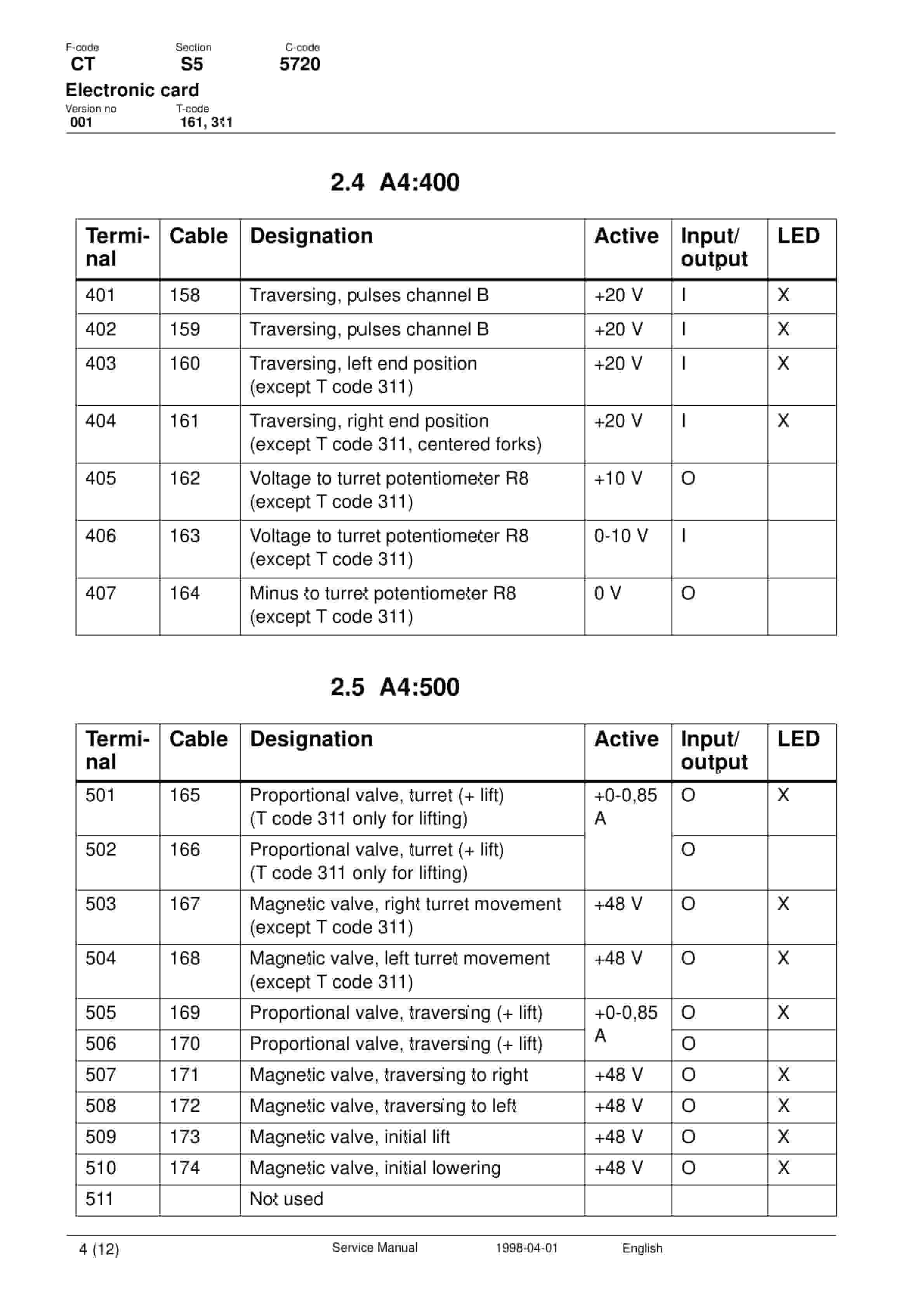
- 51.4.4. A4400
- 51.4.5. A4500
- 51.5. A4 board adjustments, T code 161
- 51.5.1. Adjustment of turret movement (end position)
- 51.5.2. Adjustment of traversing movement (offset)
- 51.5.3. Adjustment of shuttle movement (offset)
- 51.5.4. Adjustment of traversing travel
- 51.6. Troubleshooting
- 51.6.1. OK LED
- 51.7. A4 board adjustments, T code 311
- 51.7.1. Adjustment of traversing movement (offset)
- 51.7.2. Adjustment of traversing travel
- 51.8. Troubleshooting
- 51.8.1. OK LED
- 52. Hydraulic system
- 52.1. Valid from serial number
- 52.2. Serial No.
- 52.3. Main lift/steering
- 52.3.1. General
- 52.3.2. Cabin Lift right joystick upwards
- 52.3.3. Lowering the cabin – right joystick pressed down
- 52.4. Steering
- 52.4.1. Articulated centre cylinders
- 52.4.2. Installing the articulated centre cylinders
- 52.4.3. Hydraulic chart, chassis
- 52.4.4. Symbol list, chassis
- 52.4.5. Decreasing the accumulator pressure
- 52.5. Initial lift, turret fork unit
- 52.5.1. General
- 52.5.2. Fork rotation
- 52.5.3. Traversing movement
- 52.5.4. Lifting/lowering the forks
- 52.5.5. Hydraulic chart, initial lift
- 52.5.6. Symbol list, initial lift
- 53. Hydraulic system
- 53.1. Valid from serial number
Related products
-
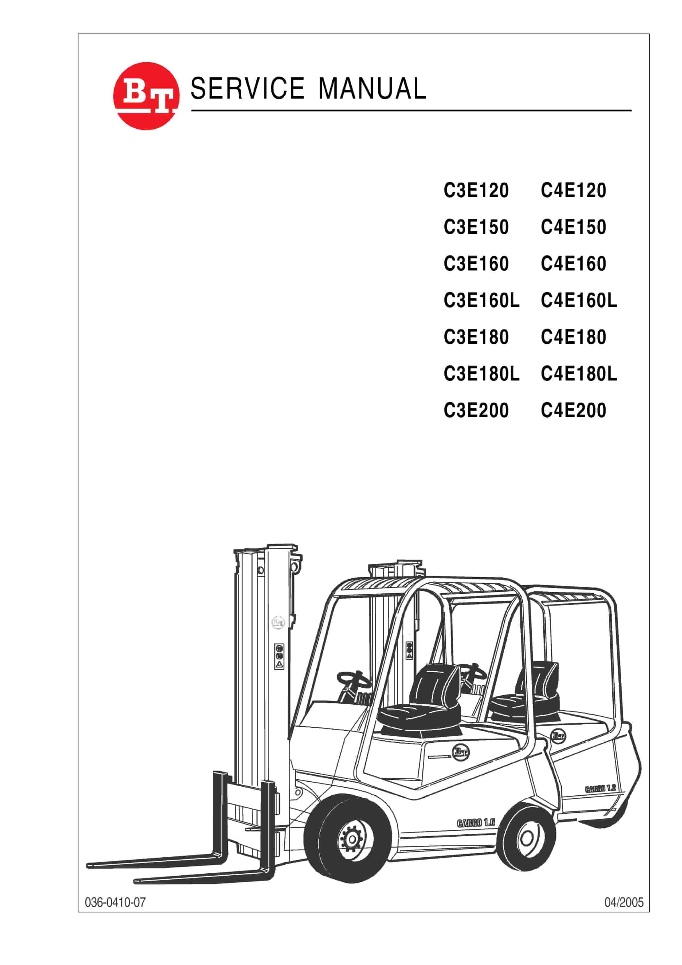
BT C3E120 to C4E200 Service Manual 036-0410-07
$30.00 Add to cart -
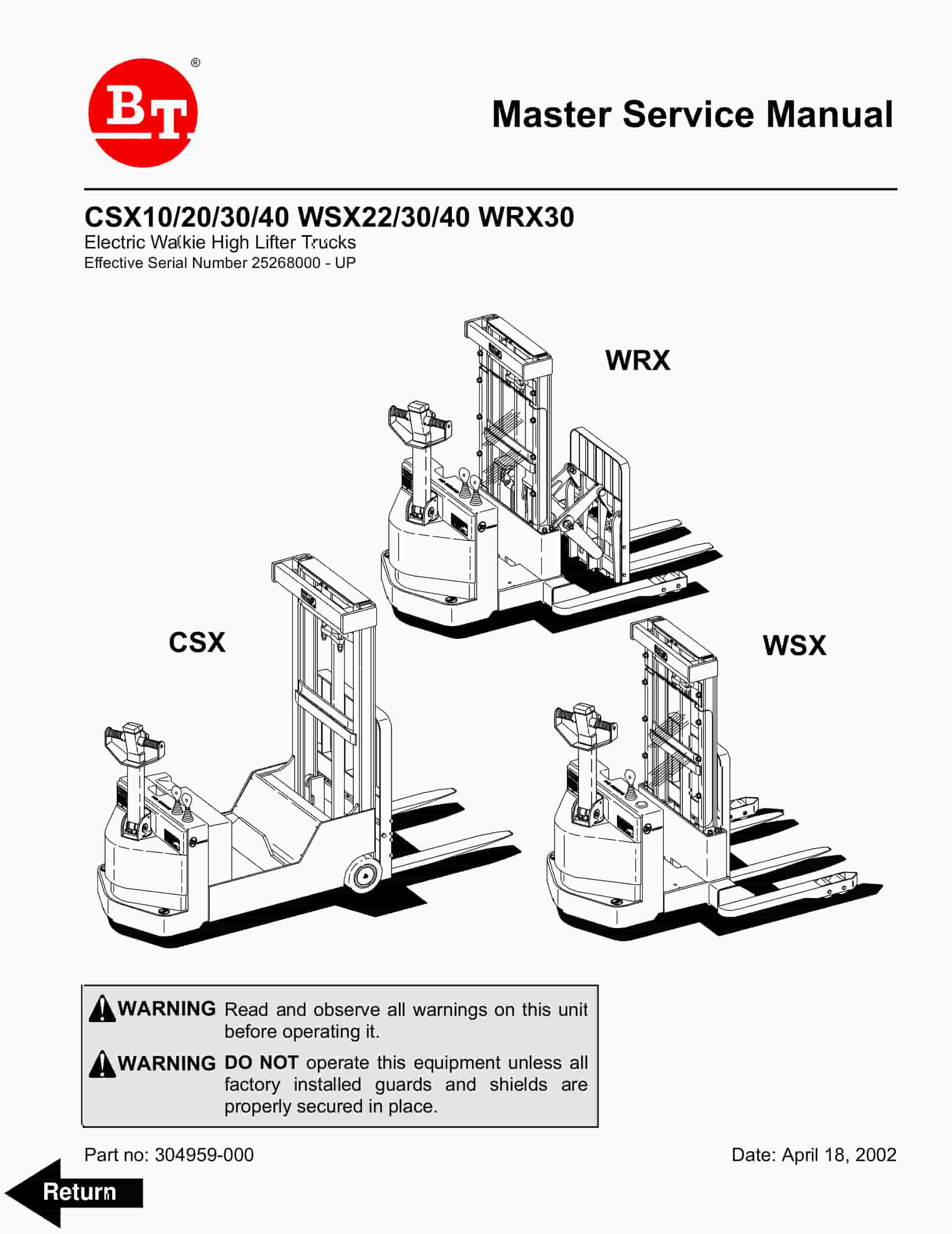
BT CSX10, CSX20, CSX30, CSX40, WSX22, WSX30, WSX40, WRX30 Electric Walkie High Lifter Truck Service Manual 304959-000
$30.00 Add to cart -
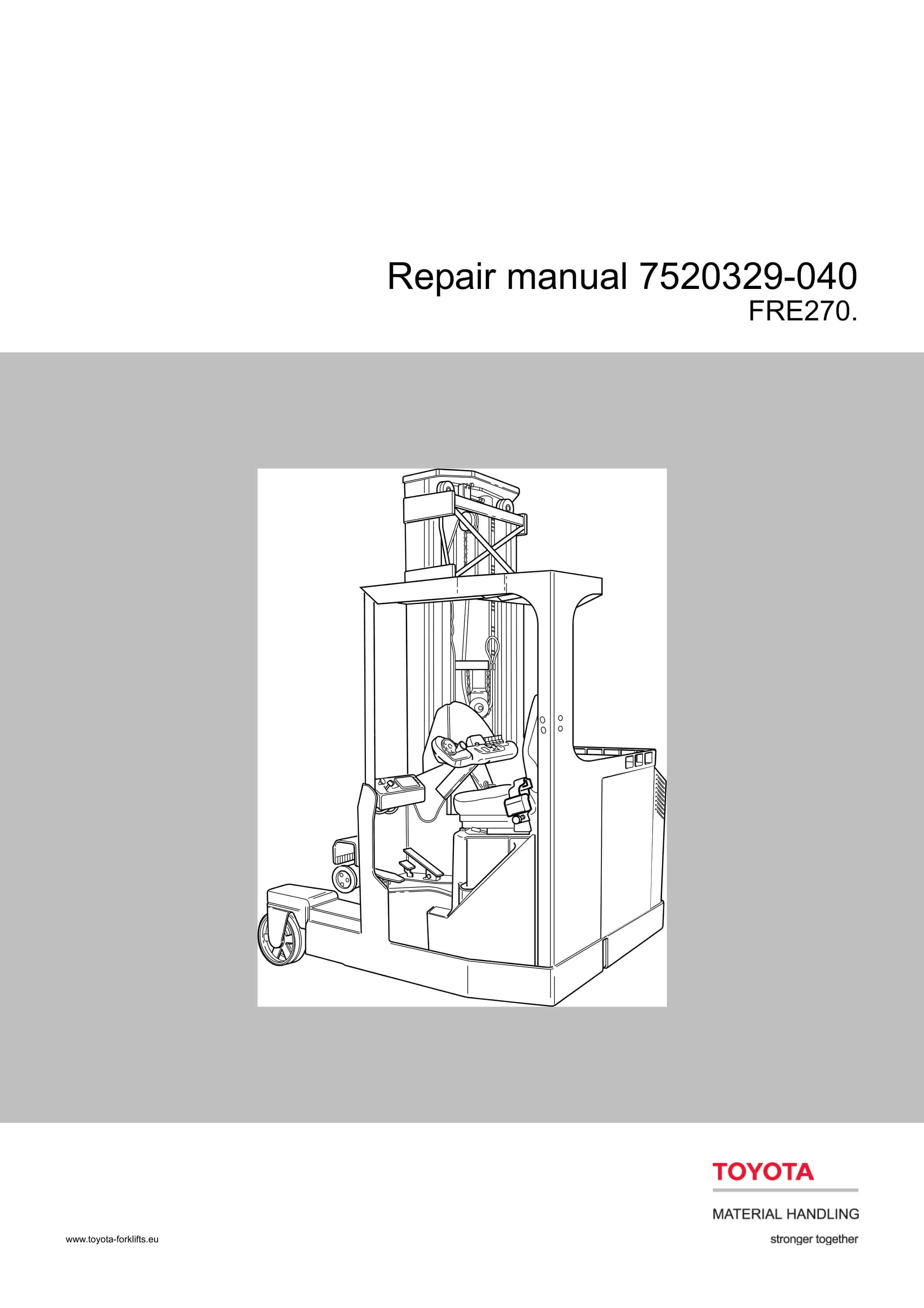
BT FRE270 Repair Manual 7520329-040
$30.00 Add to cart -
BT C3E150 to C4E200 Repair Manual 036-0434-00
$30.00 Add to cart -
BT CBE 12T to CBE 20F Service Manual 036-0410-03
$30.00 Add to cart


