


BT FRE270 Repair Manual 7520329-040
$30.00
- Type Of Manual: Repair Manual
- Manual ID: 7520329-040
- : Service Manual PDF
- Number of Pages: 336
- Size: 17.5MB
- Format: PDF
Product details
-
Model List:
- FRE270
- 1. Table of contents
- 2. General introduction
- 2.1. Presentation of the truck
- 2.2. Intended application of the truck
- 2.3. Prohibited use of the truck
- 2.4. Truck data
- 2.5. Warning symbols
- 2.6. Pictograms
- 3. General safety precautions
- 3.1. Work safety
- 3.2. Electrical systems
- 3.3. Safe lifting
- 4. Chassis C0000
- 4.1. Inspection covers C0340
- 4.1.1. Hood
- 4.1.2. Battery cover
- 4.2. Battery compartment C0390
- 4.2.1. Battery locking mechanism
- 4.3. Operators seat C0620
- 4.3.1. Adjustment
- 4.3.2. Seat switch S89
- 4.4. Operating panel
- 4.5. Driver controls (mechanical) C0640
- 4.5.1. Preconditions
- 4.5.2. Brake pedal
- 4.5.3. Accelerator
- 4.6. Brake system 3100
- 4.6.1. General
- 4.6.2. Drive motor brake (travel brake)
- 4.6.3. Multiple disc brake, support arm (travel brake)
- 4.6.4. Disc brake on the drive motor (parking brake)
- 4.7. Overhead guard/roof C0810
- 4.7.1. Overhead guard
- 4.8. Finger guards C0820
- 4.9. Signs, warnings, labels C0850
- 4.9.1. Warning and information plates
- 4.10. Truck Dimensions
- 4.11. Main components
- 5. Motors C1700
- 5.1. Pump motor C1710
- 5.1.1. Description
- 5.2. Steering motor C1730
- 5.2.1. Description
- 5.3. Fan motors C1740
- 5.3.1. Description
- 5.4. Drive motor C1760
- 5.4.1. Description
- 6. Drive unit/gear
- 6.1. General
- 6.2. Components/data for the drive unit/gear
- 6.2.1. Component location
- 6.2.2. Technical data
- 6.2.3. Gear – Exploded view
- 7. Brake system/Wheels C3000
- 7.1. Support arm brake C3180
- 7.1.1. Overview
- 7.1.2. Support arm brake replacement
- 7.1.3. Check of brake units air gap
- 7.1.4. Check of discs thickness
- 7.1.5. Assembling the brake unit
- 7.1.6. Adjusting the air gap
- 7.2. Parking brake C3370
- 7.2.1. Overview
- 7.2.2. Checking the parking brakes brake force
- 7.2.3. Checking the parking brakes air gap
- 7.2.4. Replacing the brake unit
- 7.2.5. Disassembly and check for wear
- 7.2.6. Emergency release of the parking brake
- 7.3. Drive wheel C3530
- 7.3.1. General
- 7.3.2. Removing the drive wheel
- 7.3.3. Fastening the drive wheel
- 7.4. Support arm wheel (3550)
- 7.4.1. Removing the support arm wheel from the truck
- 7.4.2. Replacing the left/right and bogie carriage wheel fork bearing
- 7.5. Wheel bolt C3530
- 7.5.1. Replacing wheel bolts
- 8. Steering system
- 8.1. General
- 8.2. Steering function
- 8.3. Effect of speed
- 8.4. Replacing the steering generator
- 8.4.1. Removal
- 8.4.2. Installing
- 9. Electrical system
- 9.1. General
- 9.1.1. Electric panel
- 9.1.2. Wiring diagram
- 9.1.3. Control panel 1
- 9.1.4. Control panel 2
- 9.1.5. Floor controls 3
- 9.1.6. Operators seat
- 9.1.7. Motor compartment – drive motor side
- 9.1.8. Motor compartment – pump motor side
- 9.1.9. Support arm
- 9.1.10. Hydraulics
- 9.1.11. Mast and cab roof
- 9.2. General description
- 9.3. Functional description
- 9.4. Input/output signals
- 9.4.1. Digital input signals
- 9.4.2. Analogue inputs
- 9.4.3. Digital output signals
- 9.4.4. Analogue signals
- 9.4.5. Communication
- 9.4.6. Other signals
- 9.4.7. Key in position 0
- 9.4.8. Key in position I
- 9.4.9. Travel direction selector
- 9.4.10. Driving
- 9.4.11. Steering
- 9.4.12. Steering wheel indicator
- 9.4.13. Braking
- 9.4.14. Fork lifting
- 9.4.15. Maximum height
- 9.4.16. Fork lowering
- 9.4.17. Reach carriage in/out
- 9.4.18. Fork tilt up/down
- 9.4.19. Fork spread/sideshift
- 9.4.20. Support arm wheel changeover
- 9.4.21. Height indicator
- 9.4.22. Height preselector
- 9.4.23. Weight calculation
- 9.4.24. Operator identification
- 9.5. Frequency converter
- 9.5.1. General description
- 9.6. Cable connections and pole bolts
- 9.6.1. ACT/ACH transistor regulators
- 9.6.2. Replacing the frequency converter
- 9.6.3. Programming
- 9.7. Adjusting the lowering speed
- 9.8. Show
- 9.9. Programming
- 9.9.1. Clock
- 9.9.2. Operator parameters (1-5)
- 9.10. Caution codes
- 9.10.1. Caution codes without registration
- 9.10.2. Warning codes with logging
- 9.11. Error codes
- 9.11.1. Error type
- 9.11.2. Safety logics
- 9.11.3. Error codes with logging
- 9.12. Operating Time
- 9.12.1. Installing a new card in the truck
- 10. Hydraulics
- 10.1. General
- 10.2. List of symbols
- 10.3. Component placement 1 (2)
- 10.4. Component placement 2 (2)
- 10.5. Adjusting fork lowering
- 10.6. Adjusting the maximum lifting capacity
- 10.7. Changing the oil pump
- 11. Main lift chain system
- 11.1. Chain inspection
- 11.2. Cleaning
- 11.3. Lubrication
- 12. Option/Extra equipment C9000
- 12.1. Working light
- 12.2. Warning flashers
- 12.3. Height indication
- 12.3.1. Function
- 12.3.2. Display
- 12.4. Height pre-selection
- 12.4.1. Function
- 12.4.2. Display
- 12.4.3. Description of the display symbols
- 12.4.4. Installing range of lift preselection
- 12.5. Programming
- 12.5.1. Programming a level
- 12.5.2. Collect level
- 12.5.3. Leave level
- 12.5.4. Deleting programmed levels
- 12.6. Automatic operation
- 12.6.1. Collect load
- 12.7. Depositing a load
- 12.8. Check
- 12.9. Parameters
- 12.9.1. Parameter 1
- 12.9.2. Parameter 2
- 12.9.3. Parameter 3
- 12.9.4. Parameter 4
- 12.9.5. Parameter 5
- 12.9.6. Parameter 7
- 12.9.7. Parameter 8
- 12.9.8. Parameter 9
- 12.10. Parameter settings
- 12.11. Error codes
- 13. Parameters
- 13.1. Setting parameters
- 13.1.1. Parameter 1
- 13.1.2. Parameter 2
- 13.1.3. Parameter 3
- 13.1.4. Parameter 4
- 13.1.5. Parameter 5
- 13.1.6. Parameter 10
- 13.1.7. Parameter 11
- 13.1.8. Parameter 12
- 13.1.9. Parameters 13 and 14
- 13.1.10. Parameters 15 and 16
- 13.1.11. Parameters 17 and 18
- 13.1.12. Parameter 19
- 13.1.13. Parameter 20
- 13.1.14. Parameter 21
- 13.1.15. Parameter 22
- 13.1.16. Parameter 23
- 13.1.17. Parameter 24
- 13.1.18. Parameter 25
- 13.1.19. Parameter 26
- 13.1.20. Parameter 27
- 13.1.21. Parameter 28
- 13.1.22. Parameter 29
- 13.1.23. Parameter 30
- 13.1.24. Parameter 31
- 13.1.25. Parameter 37
- 13.1.26. Parameter 38
- 13.1.27. Parameter 39
- 13.1.28. Parameters 40 to 42
- 13.1.29. Other parameters
- 14. Maintenance
- 14.1. Introduction, maintenance
- 14.2. Safety precautions for maintenance work
- 14.3. Cleaning and washing
- 14.3.1. Cleaning the exterior
- 14.3.2. Cleaning the motor compartment
- 14.3.3. Electrical components
- 14.4. Safe lifting
- 14.5. Checks for cracks
- 14.5.1. Visual inspection
- 14.5.2. Crack detection
- 14.6. Periodic maintenance
- 14.6.1. Maintenance schedule
- 15. Motors, C1700
- 15.1. Pump motor, C1710
- 15.1.1. Overview
- 15.1.2. Removing the pump motor
- 15.1.3. Installing the pump motor
- 15.1.4. Replacing the temperature sensor
- 15.1.5. Replacing the motor speed sensor
- 15.1.6. Cleaning
- 15.1.7. Replacing bearings
- 15.2. Steering servo motor C1730
- 15.2.1. Overview
- 15.3. Replacing the steering motor
- 15.3.1. Removal
- 15.3.2. Installation
- 15.4. Removing and installing the carbon brushes
- 15.5. Fan motors C1740
- 15.5.1. Overview
- 15.5.2. Replacing the frequency converter fan
- 15.5.3. Replacing the motor compartment fan
- 15.6. Drive motor, C1760
- 15.6.1. Overview
- 15.6.2. Removing the drive motor
- 15.6.3. Fastening the drive motor
- 15.6.4. Replacing the temperature sensor
- 15.6.5. Replacing the motor speed sensor
- 15.6.6. Disassembling
- 15.6.7. Cleaning
- 15.6.8. Replacing bearings
- 15.6.9. Assembly
- 16. Drive gear C2000
- 16.1. Replacing the drive gear
- 16.1.1. Removing the drive motor
- 16.1.2. Replacing the gear wheel
- 16.1.3. Removing the drive gear
- 16.1.4. Replacing the steering bearing
- 16.1.5. Installing the drive gear
- 16.1.6. Fastening the drive motor
- 16.2. Oil check/replacement
- 16.2.1. Checking/refilling the oil
- 16.2.2. Changing the oil
- 16.3. Repairs
- 16.3.1. Replacing the drive shaft sealing ring
- 16.3.2. Sealing the upper cover
- 16.3.3. Sealing the lower cover
- 17. Instructions for disposal
- 17.1. General
- 17.2. Marking of plastics
- 17.2.1. General marking of products and packaging material
- 17.2.2. Marking according to the manufacturers standards
- 17.3. Pressure vessels
- 17.3.1. Gas dampers
- 17.4. Sorting categories
- 18. Wiring diagram
- 18.1. Components
- 18.2. Symbol list
- 18.3. Wiring diagram
- 19. Hydraulics schematics
- 19.1. Components
- 19.2. Hydraulics schematics
- 19.2.1. Diagram
- 19.2.2. Valve layout
- 19.2.3. Valve layout
- 20. Tools
- 20.1. Super Seal contact
- 20.2. AMP micro timer
- 20.3. AMP contacts
- 20.4. MQS contacts
- 20.5. CPC contacts
- 20.6. Miscellaneous tools
- 21. Service data and grease specifications
- 21.1. General tightening torques
- 21.1.1. Galvanised, non-oiled screws
- 21.1.2. Untreated oiled bolts
- 21.2. Oil and grease specification
- 22. Technical data
Related products
-
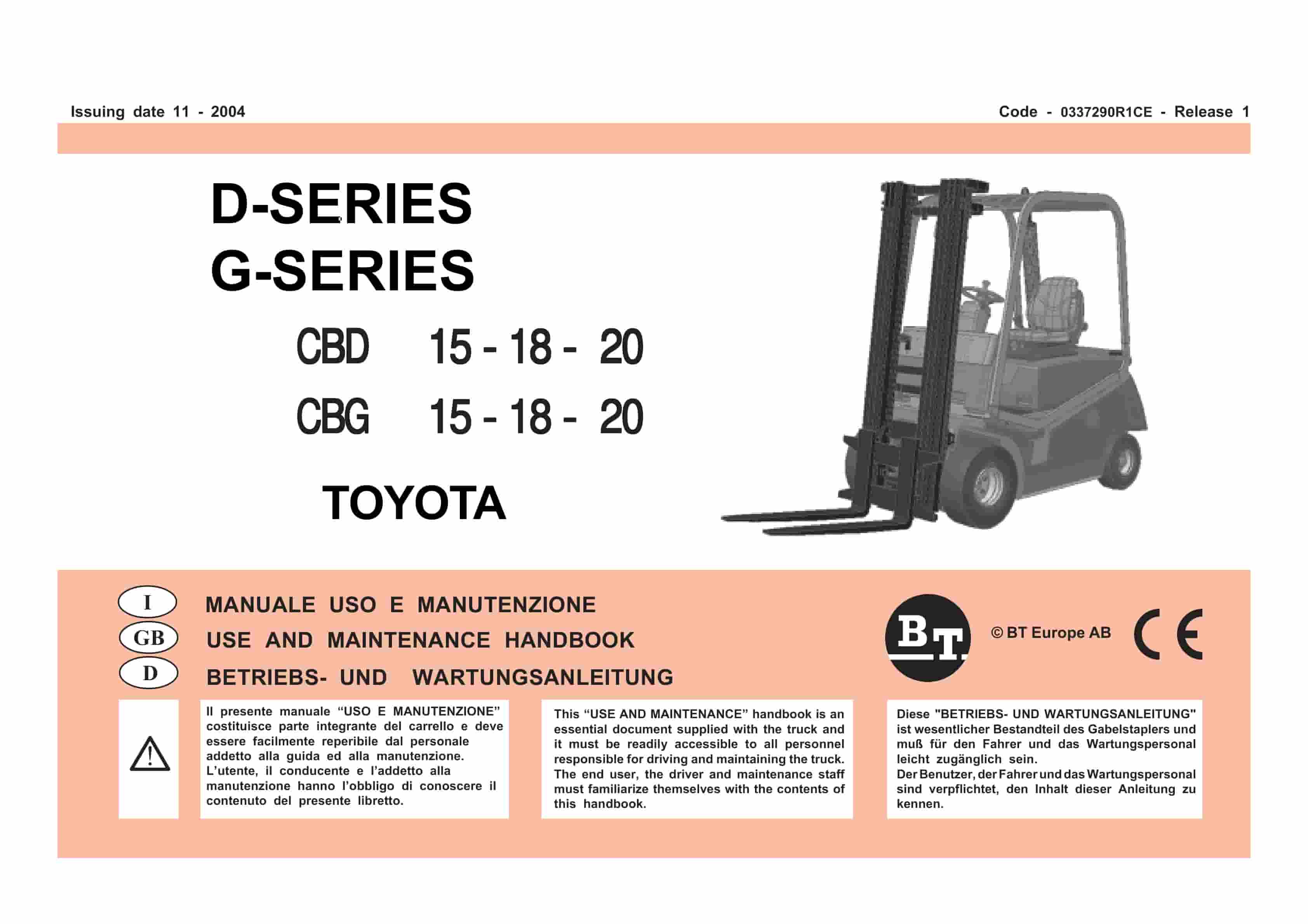
BT D-G-Series CBD15, CBD18, CBD20, CBG15, CBG18, CBG20 Use And Maintenance Handbook 0337290R1CE
$30.00 Add to cart -
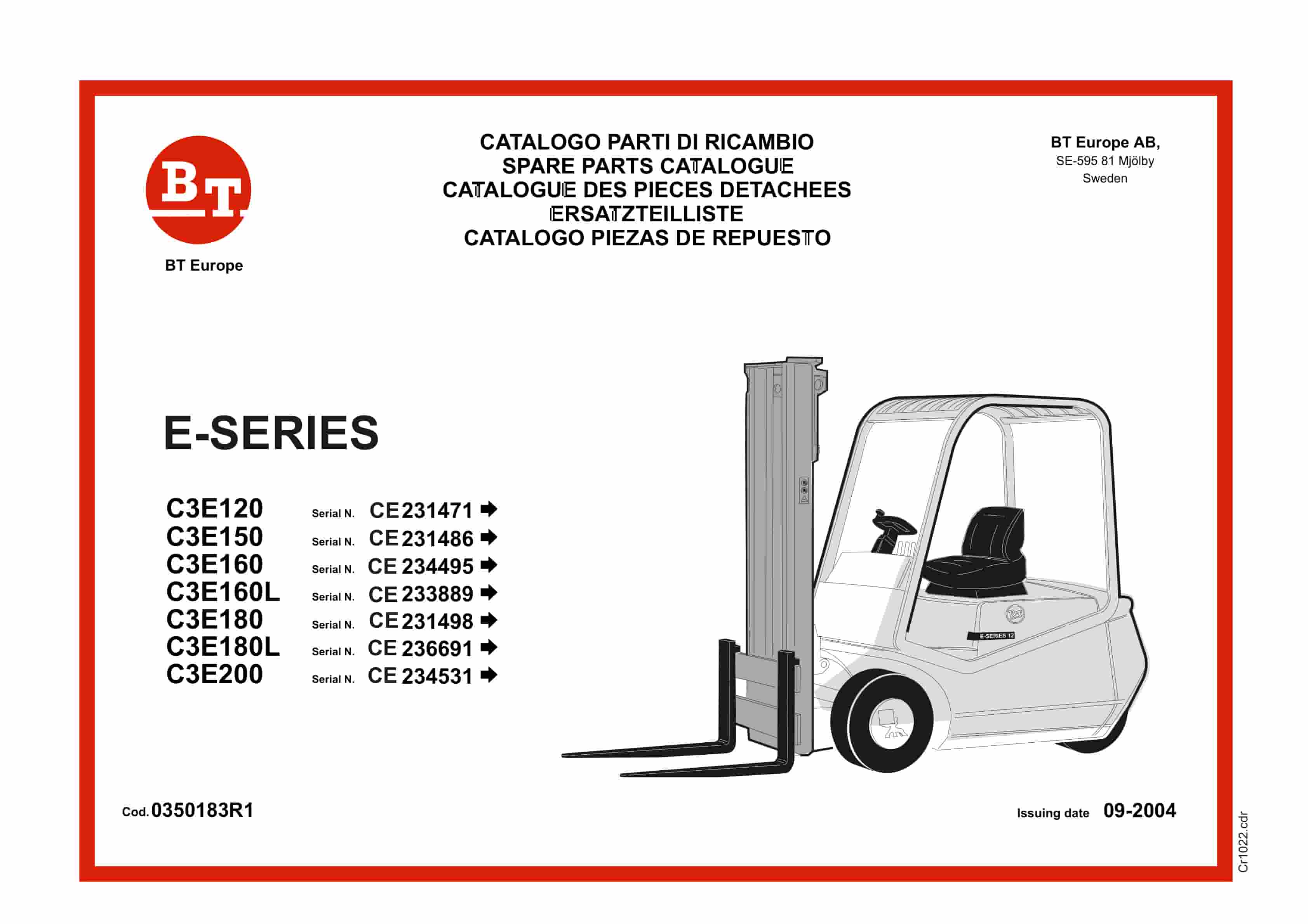
BT E-Series C3E120 to C3E200 Service Manual 0350183R1
$30.00 Add to cart -
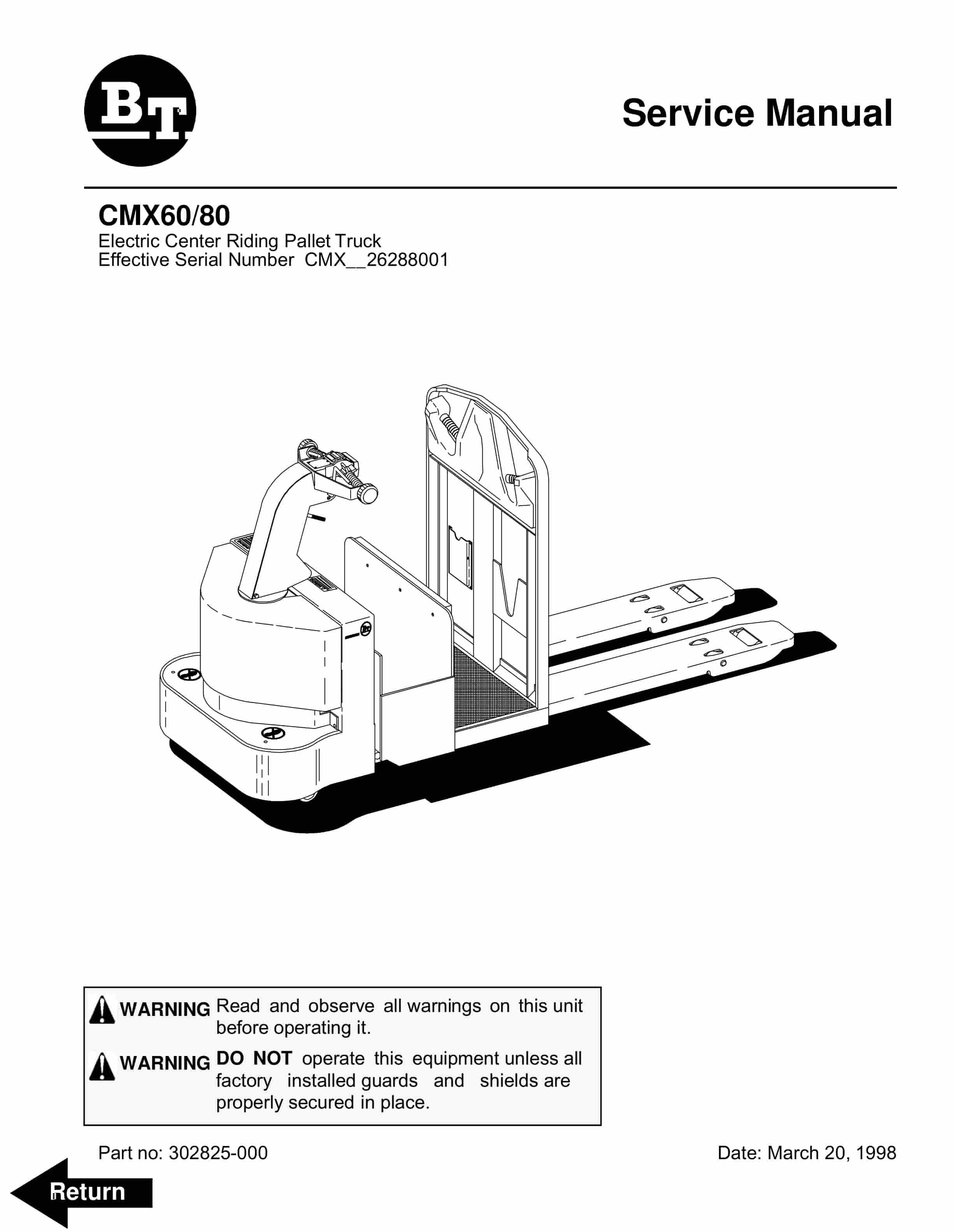
BT CMX60, CMX80 Electric Center Riding Pallet Truck Service Manual 302825-000
$30.00 Add to cart -
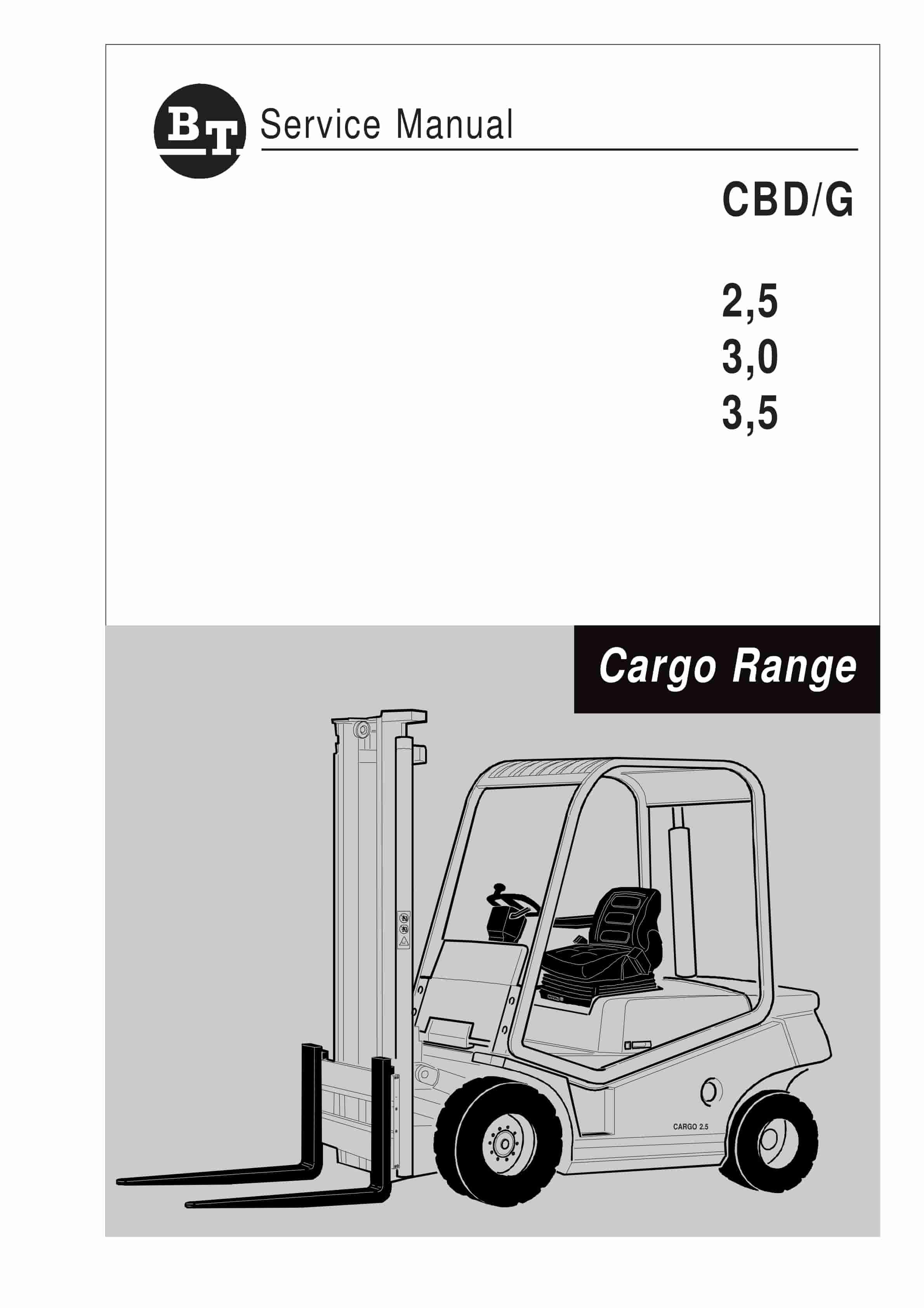
BT CBD-G 2.5, 3.0, 3.5 Service Manual 036-0405-01
$30.00 Add to cart -
BT C3E150 to C4E200 Repair Manual 036-0434-00
$30.00 Add to cart