


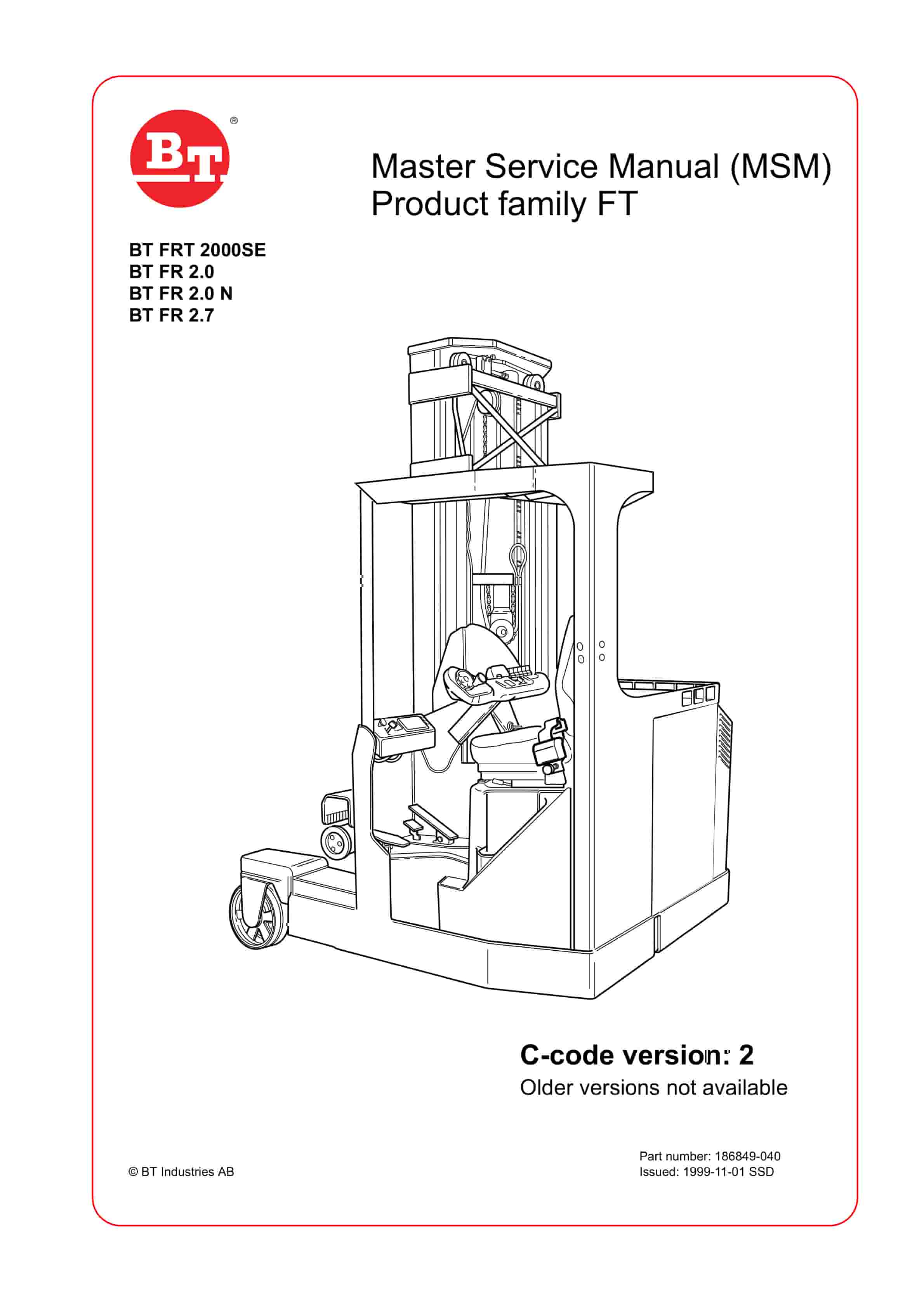
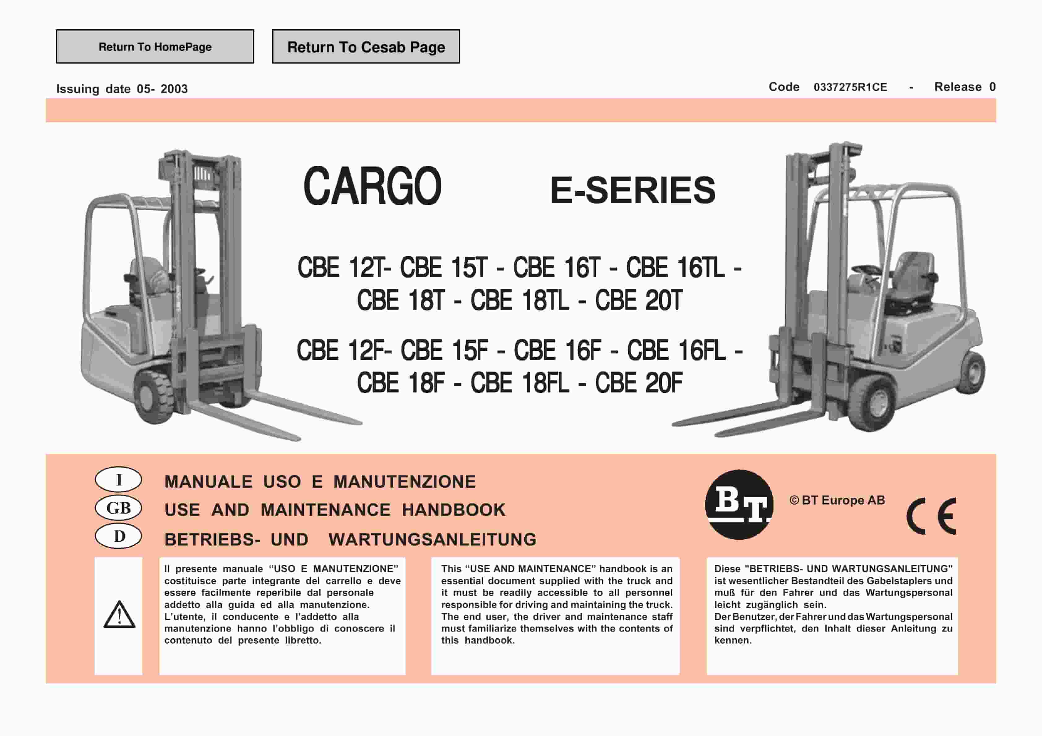
BT Service Manual PDF
BT CARGE E-Series CBE 12T-20T, CBE 12F-20F Use And Maintenance Handbook 0337275R1CE
$30.00
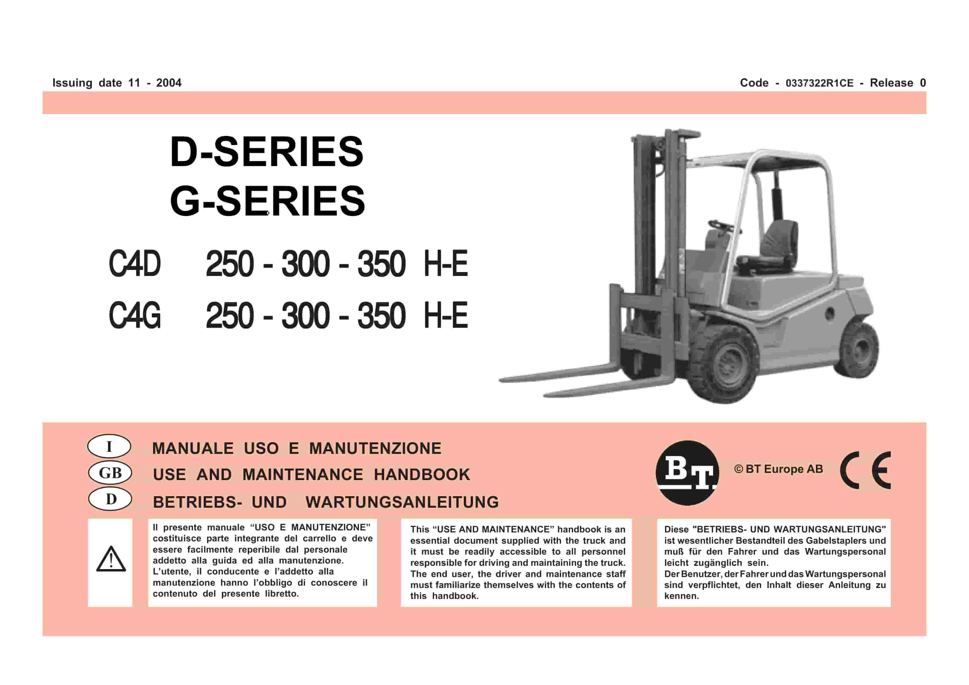
BT Service Manual PDF
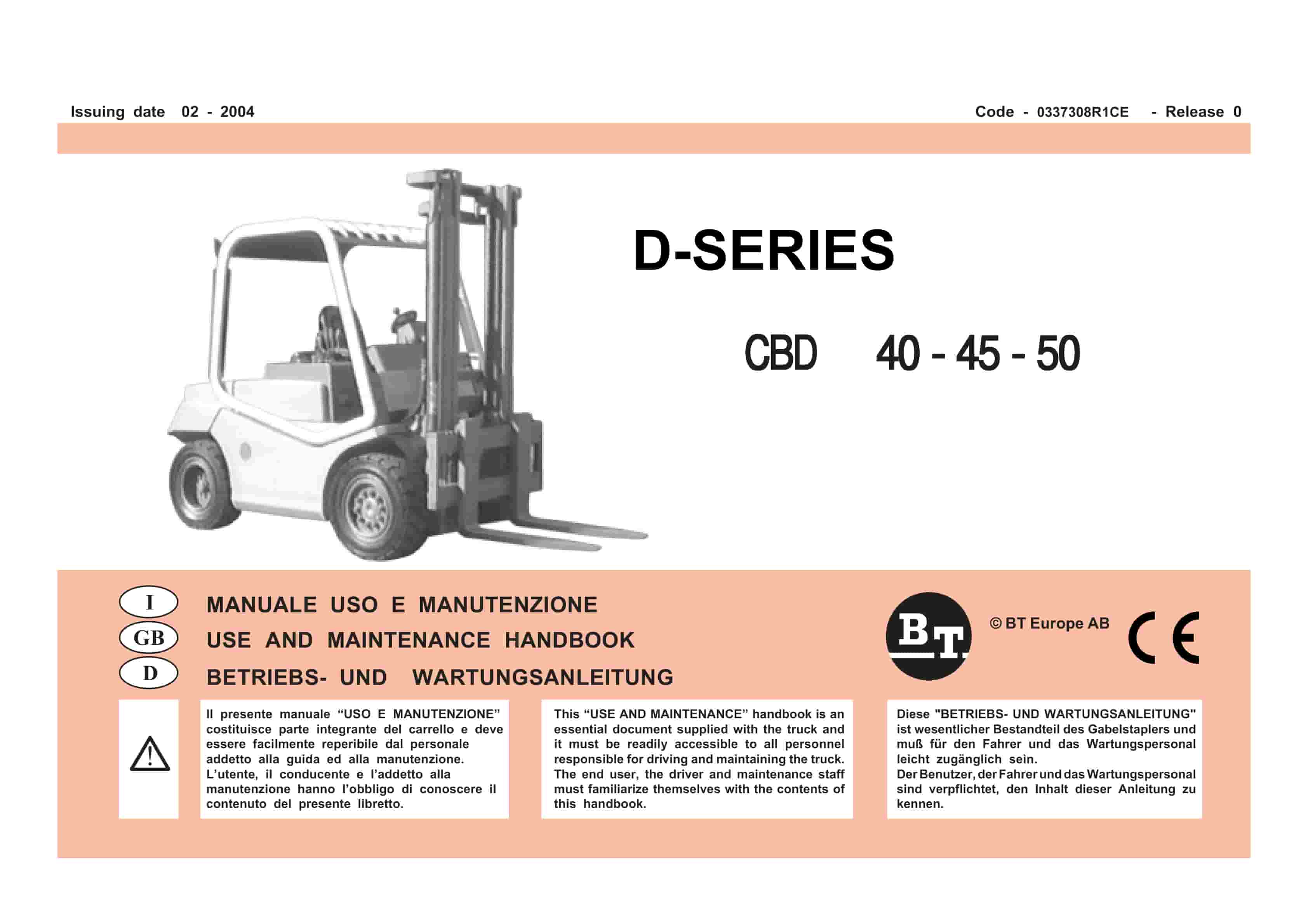
BT D-Series CBD40, CBD45, CBD50 Use And Maintenance Handbook 0337308R1CE
$30.00
BT Service Manual PDF
BT CARGE E-Series CBE 12T-20T, CBE 12F-20F Use And Maintenance Handbook 0337275R1CE
BT Service Manual PDF
BT D-Series CBD40, CBD45, CBD50 Use And Maintenance Handbook 0337308R1CE