


BT PMX Electric Low Lift Pallet Truck Repair Manual 9502 302266-000
$30.00
- Type Of Manual: Repair Manual
- Manual ID: 9502 302266-000
- : Service Manual PDF
- Number of Pages: 144
- Size: 8.7MB
- Format: PDF
Product details
-
Model List:
- PMX Electric Low Lift Pallet Truck
- 1. Front Cover
- 2. Table of Contents
- 3. Section 0 – Maintenance
- 3.1. Truck Identification
- 3.2. System Operation
- 3.3. Specifications
- 3.4. Inch (SAE) and Metric Fasteners
- 3.4.1. Introduction
- 3.4.2. Nomenclature, Threads
- 3.4.3. Figure 1 – Thread Design
- 3.4.4. Strength Identification
- 3.4.5. Table 1 – Bolts and Screws
- 3.4.6. Table 2 – Studs and Nuts
- 3.4.7. Table 3 – Torque Nuts
- 3.4.8. Table 4 – Torque Nuts with Nylon Insert
- 3.4.9. Table 5 – Conversion Table for Metric and English Units
- 3.4.10. Table 6 – Torque Values for Coarse Threaded Metric Fasteners
- 3.5. Maintenance and Adjustments
- 3.5.1. Planned Maintenance Schedule
- 3.5.2. Services to be Performed Monthly or Every 200 Operating Hours
- 3.5.3. Services to be Performed Annually or Every 2000 Operating Hours
- 3.6. Troubleshooting
- 3.7. Component Removal and Installation
- 3.8. Component Repair
- 4. Section 1.0 – Transmission
- 4.1. Transmission Assembly
- 4.2. Description
- 4.3. System Operation
- 4.4. Specifications
- 4.5. Maintenance and Adjustments
- 4.5.1. Brake Theory of Operation
- 4.5.2. Brake Adjustment
- 4.5.3. Transmission Pivot Bearing Adjustment
- 4.6. Troubleshooting
- 4.7. Component Removal and Installation
- 4.7.1. Transmission Removal and Installation
- 4.7.2. Drive Wheel Removal and Installation
- 4.7.3. Axle Seal Removal and Installation
- 4.7.4. Brake Linkage Removal and Installation
- 4.7.5. Brake Shoe Removal and Installation
- 4.8. Component Repair
- 4.8.1. Transmission Disassembly and Assembly
- 5. Section 2.0 – Electrical
- 5.1. Component Identification
- 5.1.1. Volt Electrical Assembly
- 5.1.2. Volt Panel Assembly
- 5.1.3. Volt Electrical Assembly
- 5.1.4. Volt Panel Assembly
- 5.2. System Operation – 12 volt PMX
- 5.2.1. Battery Connected and Emergency Disconnect Push Button Switch Pulled Out to Run Position
- 5.2.2. Key Switch Turned On
- 5.2.3. Control Handle Pulled Down Brakes Released and Brake Interlock Switch Closed
- 5.2.4. Reverse Travel (Fork Direction) Switch is Closed
- 5.2.5. Forward Travel (Control Handle Direction) Switch is Closed
- 5.2.6. Curtis PMC Controller Power Circuits
- 5.2.7. Accelerator Potentiometer Circuits
- 5.2.8. Emergency Reverser Switch
- 5.2.9. Lift Pallet Forks
- 5.2.10. Lower Pallet Forks
- 5.3. System Operation – 24 volt PMX
- 5.3.1. Battery Connected and Emergency Disconnect Push Button Switch Pulled Out to Run Position
- 5.3.2. Key Switch Turned On
- 5.3.3. Control Handle Pulled Down Brakes Released and Brake Interlock Switch Closed
- 5.3.4. Reverse Travel (Fork Direction) Switch is Closed
- 5.3.5. Forward Travel (Control Handle Direction) Switch is Closed
- 5.3.6. Prime-Drive 200 Controller Power Circuits
- 5.3.6.1. Basics of Circuit Operation
- 5.3.6.2. Control Features
- 5.3.7. Accelerator Potentiometer Circuit
- 5.3.8. Emergency Reverser Switch
- 5.3.9. Lift Pallet Forks
- 5.3.10. Lower Pallet Forks
- 5.4. Specifications
- 5.5. Maintenance and Adjustments
- 5.5.1. Maintenance
- 5.5.2. Adjustments
- 5.5.2.1. Lift Limit Switch
- 5.5.2.2. Accelerator Potentiometer
- 5.5.2.3. Brake Interlock Switch
- 5.5.2.4. Table of Pot Settings and Associated Voltages Per Cell
- 5.5.2.5. Controller Adjustments – 12 Volt
- 5.5.2.6. Controller Adjustments – 24 Volt
- 5.6. Troubleshooting
- 5.6.1. Troubleshooting Chart Index
- 5.6.2. Troubleshooting Charts
- 5.6.3. Battery Pack Schematic
- 5.6.4. Troubleshooting the Charger Used in the PMX Battery Pack
- 5.7. Component Removal and Installation
- 5.7.1. Drive Motor Removal and Installation
- 5.7.2. Drive Motor Brush Removal and Installation
- 5.7.3. Pump and Motor Removal and Installation
- 5.7.4. Pump Motor Brush Removal and Installation
- 5.7.5. Switch, Control
- 5.7.6. Contactor Tips
- 5.8. Component Repair
- 5.8.1. Table 1
- 5.8.2. Table 2
- 6. Section 3.0 – Hydraulics
- 6.1. Component Identification
- 6.1.1. Hydraulic Schematic
- 6.1.2. Hydraulic Schematic Symbols
- 6.2. System Operation
- 6.3. Specifications
- 6.4. Maintenance and Adjustments
- 6.5. Troubleshooting
- 6.5.1. Hydraulic Pump Assembly
- 6.5.2. Relief Valve
- 6.5.3. Removing Solenoid Operated Release Valve
- 6.5.4. Install Solenoid Operated Release Valve
- 6.6. Component Removal and Installation
- 6.6.1. Pump and Motor Removal and Installation
- 6.6.2. Reservoir and Pump Removal and Installation
- 6.6.3. Cylinder Removal and Installation
- 6.7. Component Repair
- 6.7.1. Cylinder Disassembly
- 6.7.2. Inspection
- 6.7.3. Assembly
- 7. Section 4.0 – Frame
- 7.1. Component Identification
- 7.2. System Operation
- 7.3. Specifications
- 7.4. Maintenance and Adjustments
- 7.5. Troubleshooting
- 7.6. Component Removal and Installation
- 7.6.1. Control Handle Head
- 7.6.2. Load Wheels
- 7.6.3. Pull Rod Bushings
- 7.6.4. Carrier Frame Bushings
- 8. Back Cover
Related products
-
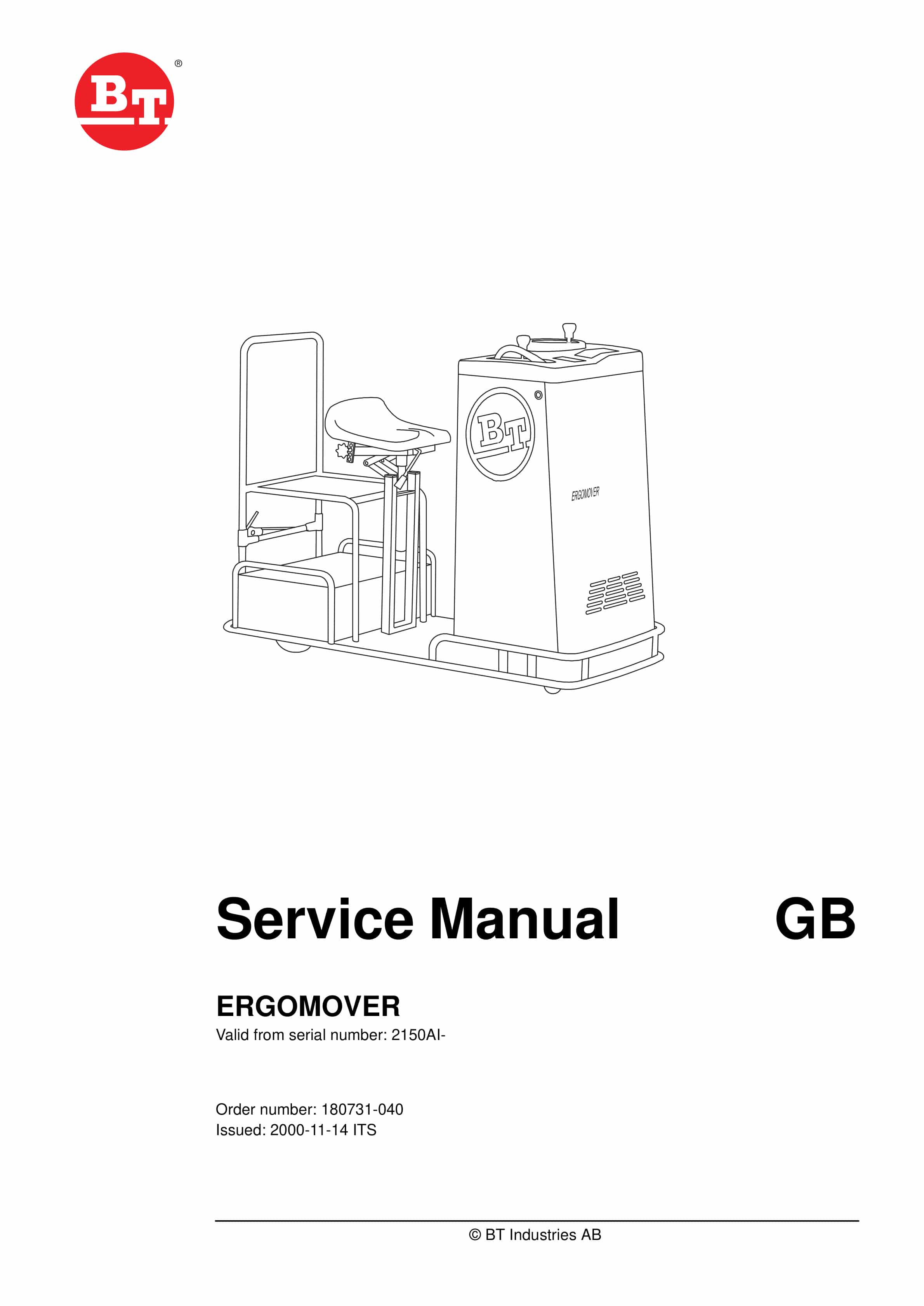
BT ERGOMOVER Service Manual 180731-040
$30.00 Add to cart -
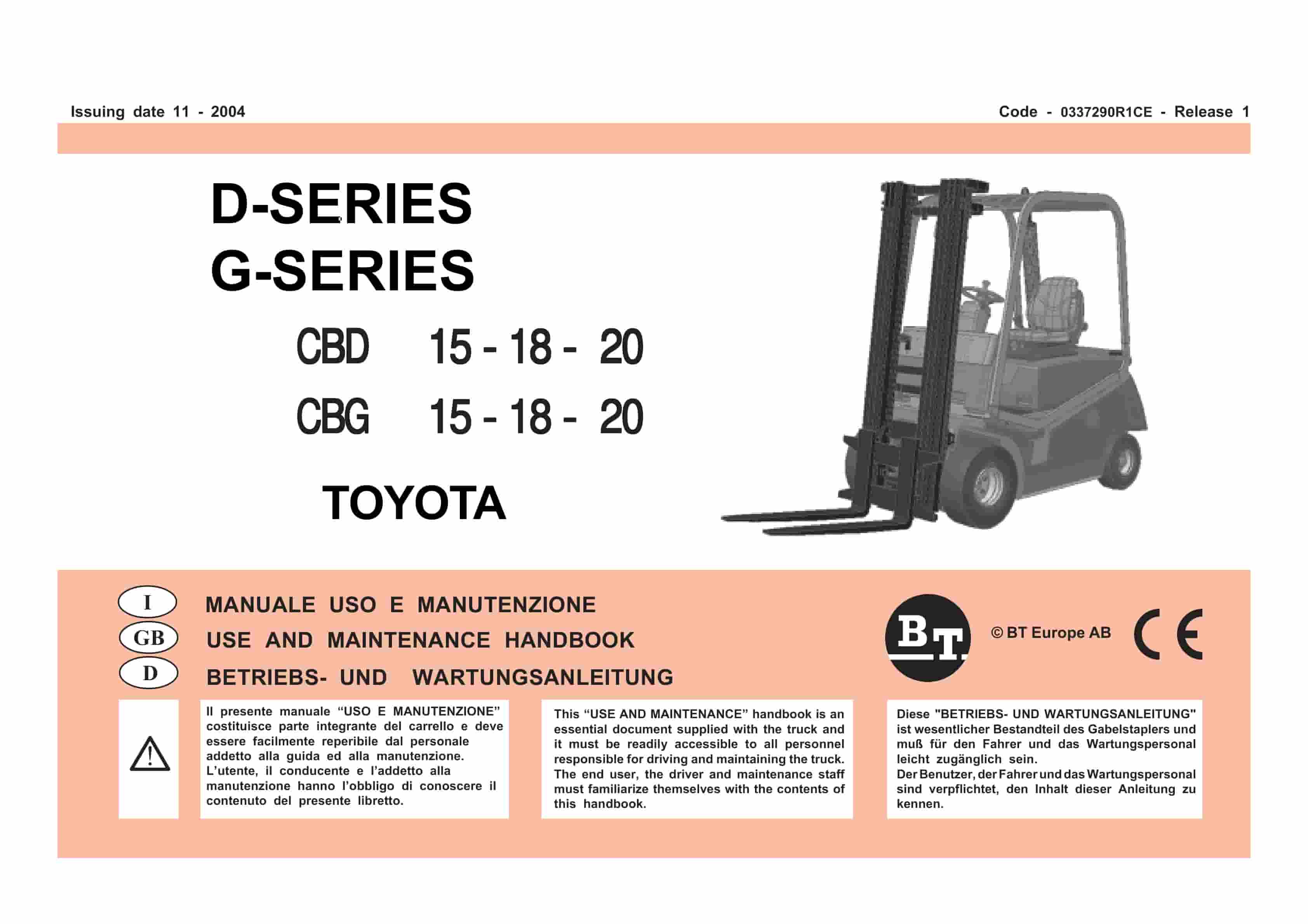
BT D-G-Series CBD15, CBD18, CBD20, CBG15, CBG18, CBG20 Use And Maintenance Handbook 0337290R1CE
$30.00 Add to cart -
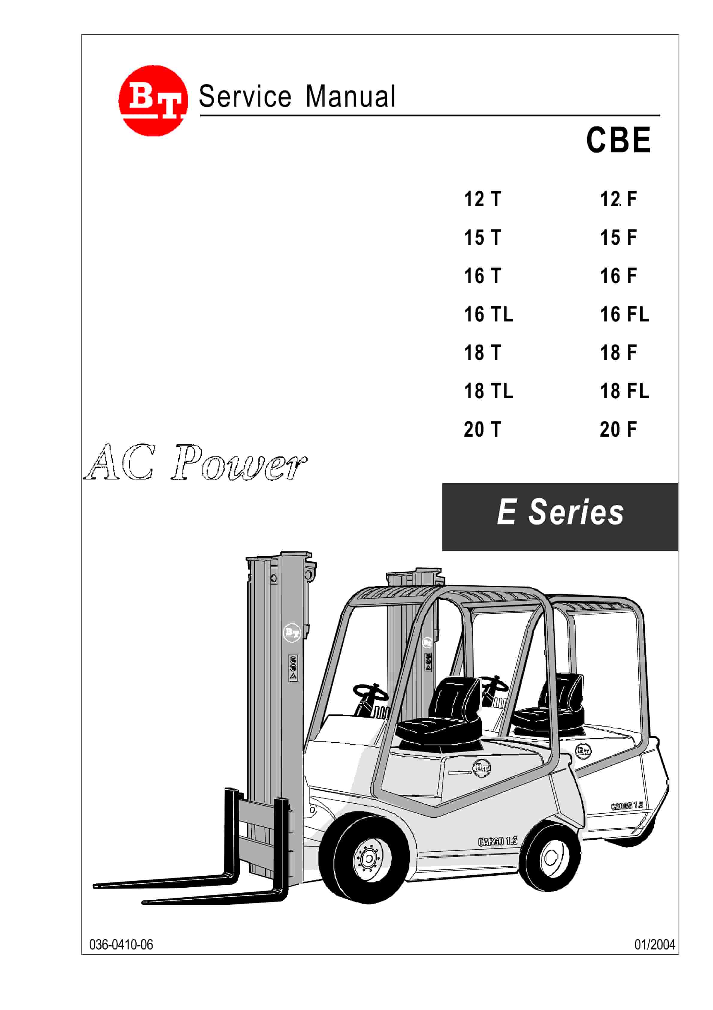
BT CBE 12T to CBE 20F Service Manual 036-0410-03
$30.00 Add to cart -
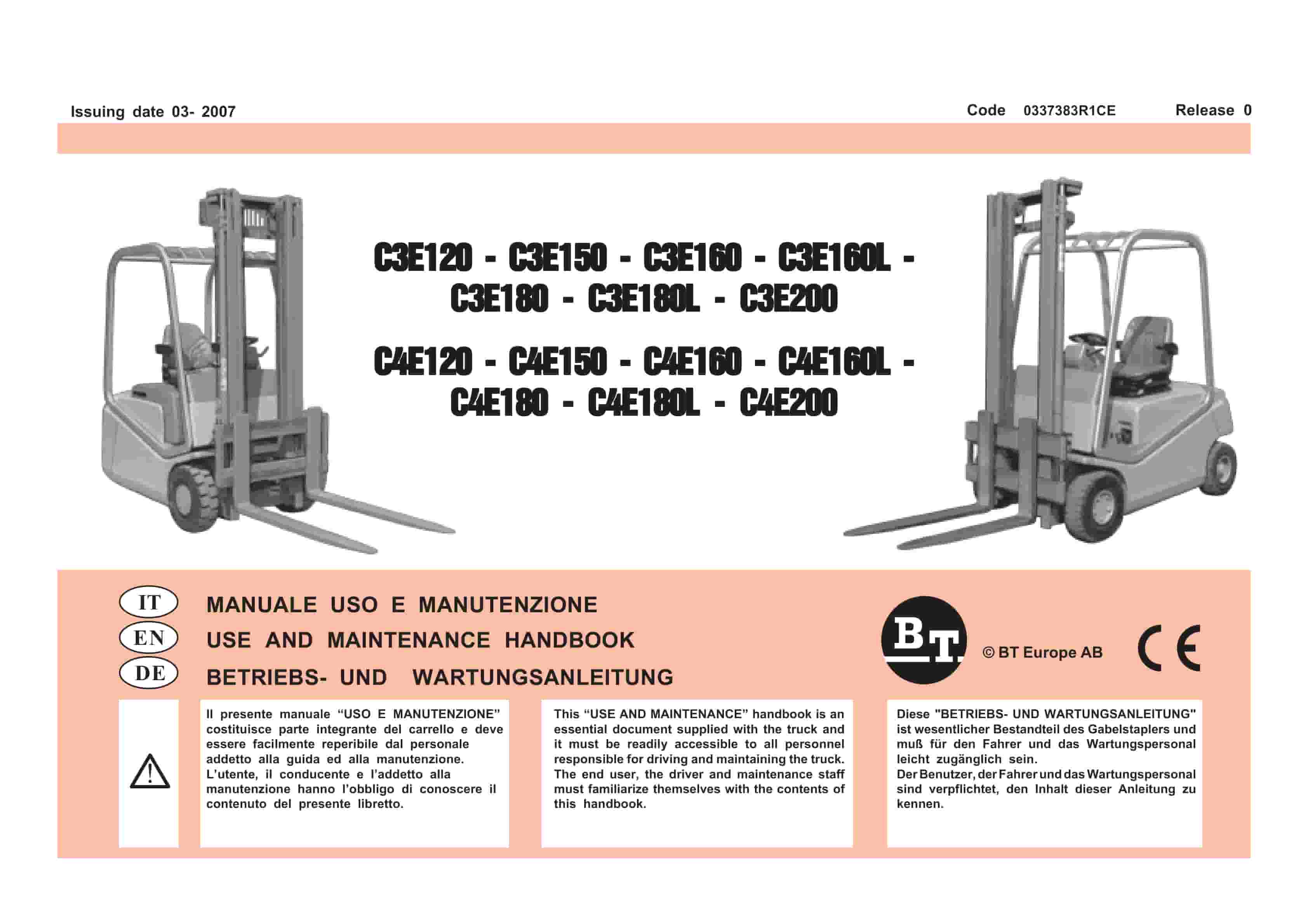
BT C3E120 to C4E200 Use And Maintenance Handbook 0337383R1CE
$30.00 Add to cart -
BT CMX-65, CMX-80 Center Control Riding Pallet Truck Service Manual 302825-000
$30.00 Add to cart