

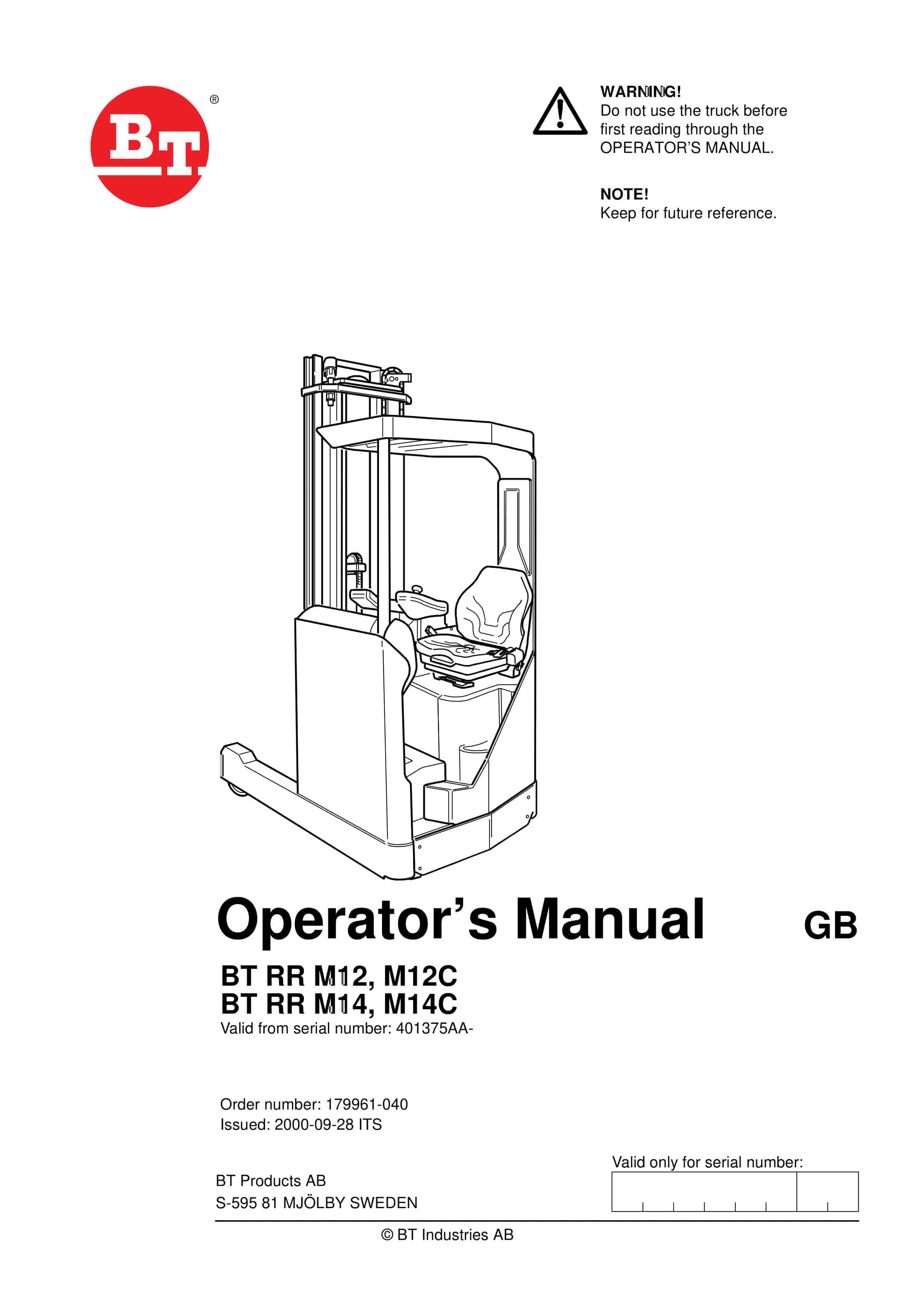
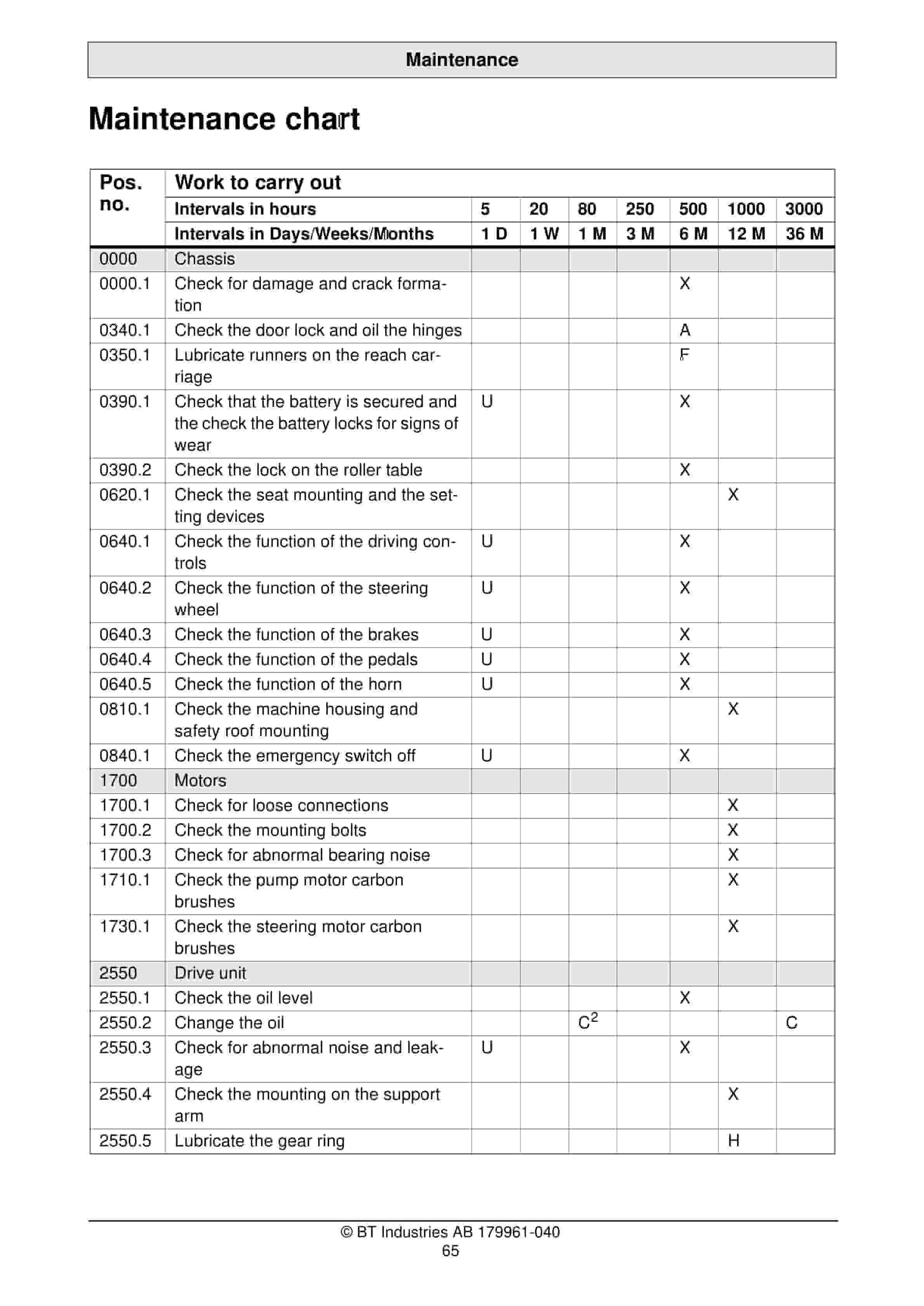
BT RR M12, RR M12C Operator Manual 179961-040
$30.00
- Type Of Manual: Operator Manual
- Manual ID: 179961-040
- : Operator Manual PDF
- Number of Pages: 80
- Size: 3.6MB
- Format: PDF
Product details
-
Model List:
- RR M12, RR M12C
- 1. BT RR M12, M12C BT RR M14, M14C
- 1.1. Valid from serial number 401375AA-
- 1.2. Order number 179961-040
- 1.2.1. Issued 2000-09-28 ITS
- 2. Safety regulations
- 2.1. Warning symbols
- 2.1.1. Warning levels
- 2.1.2. Prohibitory symbols
- 2.1.3. Ordinance symbols
- 2.2. General safety regulations
- 2.2.1. Operating the truck
- 2.2.2. Operators responsibility
- 2.2.3. Working area
- 2.2.4. Driving and conduct while driving
- 2.2.5. Handling loads
- 2.2.6. Parking the truck
- 2.2.7. Handling the battery
- 2.2.8. Maintenance and repair
- 3. Warning and information plates and symbols
- 3.1. Modification plate
- 3.2. Identification plate, truck
- 3.3. Capacity plate
- 3.4. Serial number
- 3.5. Hydraulic oil filling
- 3.6. Parking brake and travel direction selector (accessories)
- 3.7. Lifting points
- 3.8. Hydraulic controls lift/lowering, mast in/out, fork tilt, sideshift and additional hydraulic …
- 3.9. Do not walk under elevated load
- 3.10. Maximum height for rated capacity
- 3.11. Identification plate, mast
- 4. Presentation to BTs reach trucks
- 4.1. Application areas for BTs reach trucks
- 4.2. Prohibited applications for BTs reach trucks
- 4.3. Truck data
- 4.3.1. Truck type
- 4.4. Truck dimensions
- 4.4.1. Dimensions (mm)
- 4.5. Identification plate
- 4.6. Modification plate
- 4.7. Identification plate, mast
- 5. Main components
- 5.1. Hydraulic valves The valves are located to provide easy access.
- 5.2. Battery 48 V with different Ah values.
- 5.3. Recharging connector The battery is recharged via this permanently attached recharging connec…
- 5.4. Control circuit fuse 10A, BT part no. 161640-100. Fuse for electrical steering wheel 30 A, B…
- 5.5. Hydraulic unit Pump motor, pump and oil tank integrated in a compact unit.
- 5.6. Drive unit with brake Drive motor, gears and drive wheel combined into a compact unit. Electr…
- 5.7. Electrical steering motor Mounted with the drive gear to provide a compact design.
- 5.8. Identification plate With model designation, serial number, year of manufacture, weight witho…
- 5.9. Operators seat The seat is fully adjustable to provide optimal operator comfort.
- 5.10. Serial number The serial number plate fitted to the chassis.
- 5.11. Cover Easily swivelled to provide good access for servicing.
- 5.12. Pedals Accelerator with optional direction selector, travel brake and safety pedal.
- 5.13. Control console The control console can be adjusted to a suitable height and angle to obtain…
- 5.14. Instrument panel This provides information on the trucks running time, time indication, err…
- 5.15. Mast The mast is a clear-view model and is equipped with an identification plate with type d…
- 5.16. Electronics All the electronics collected in a protected compartment.
- 5.17. Drive motor fuse RR M12, M14 125 A, BT part no. 29584.
- 5.18. Pump motor fuse RR M12, M14 160 A, BT part no. 29223.
- 6. Controls and instruments
- 6.1. Emergency switch off
- 6.2. Key switch
- 6.3. Display
- 6.4. Operator identification and operator parameters
- 6.5. Switches and indicator lamps
- 6.6. Control console
- 6.7. Controls for control console position
- 6.8. Operators seat
- 6.9. Pedals
- 6.10. Cover lock
- 6.11. Emergency switch off (1)
- 6.12. Key switch (2)
- 6.13. Display (3)
- 6.13.1. Parking brake indicator (A)
- 6.13.2. Direction indicator (B)
- 6.13.3. Time display (C)
- 6.13.4. Display of hour meter reading/error codes (D)
- 6.13.5. Character
- 6.14. Operator identification and operator parameters (4)
- 6.15. Switches and indicator lamps (5)
- 6.15.1. Character
- 6.15.2. Symbol on the switch
- 6.15.3. Function
- 6.16. Control console (6)
- 6.16.1. Steering (A)
- 6.16.2. Horn (D)
- 6.16.3. Hydraulic controls (E)
- 6.16.4. Function
- 6.17. Controls for control console position (7)
- 6.17.1. WARNING
- 6.18. Operators seat (8)
- 6.18.1. Adjustment
- 6.19. Pedals (9)
- 6.19.1. Safety pedal (A)
- 6.19.2. Safety pedal with direction selector (B)
- 6.19.3. Travel brake (C)
- 6.19.4. Accelerator (D)
- 6.19.5. Accelerator and direction selector (E)
- 6.20. Cover lock (10)
- 6.21. Display and programming
- 6.21.1. Display
- 6.21.2. Programming
- 6.22. Warning codes
- 6.22.1. Character
- 6.22.2. Code No.
- 6.22.3. Error type
- 6.22.4. Probable cause
- 6.22.5. Effect on the truck
- 6.23. Error codes
- 6.23.1. Character
- 6.23.2. Code No.
- 6.23.3. Error type
- 6.23.4. Probable cause
- 6.23.5. Effect on the truck
- 7. Accessories
- 7.1. BT TLS Truck Logging System
- 7.1.1. Keyboard version
- 7.1.2. Logging using a code (5 digit)
- 7.1.3. Login with fault reporting (51 digit)
- 7.1.4. Login with extra code (53 digit)
- 7.1.5. Login with extra code and fault reporting (531 digit)
- 7.1.6. Changing the personal three digit code
- 7.1.7. Code card version
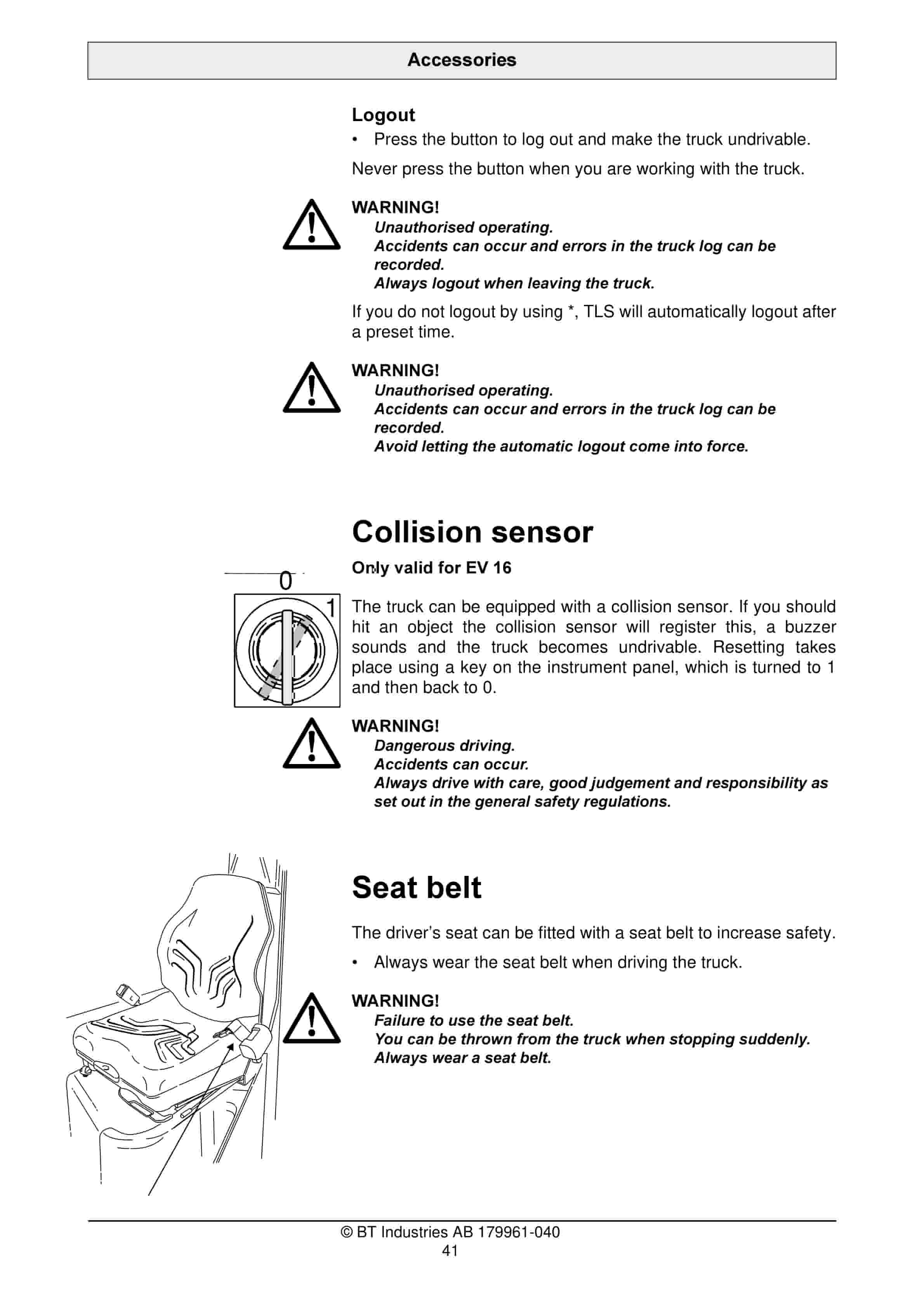
- 7.2. Collision sensor
- 7.2.1. WARNING
- 7.3. Seat belt
- 7.3.1. WARNING
- 7.4. Load support
- 7.5. Extension forks
- 7.5.1. WARNING
- 7.6. Boom attachment
- 7.6.1. WARNING
- 7.7. Clamping/rotating unit
- 7.7.1. WARNING
- 7.8. Telescopic forks
- 7.8.1. WARNING
- 7.9. Sideshift/fork spread
- 7.9.1. WARNING
- 7.10. Warning light
- 7.11. Working light
- 7.12. Deceleration
- 7.13. Operator protection
- 7.13.1. WARNING
- 7.14. Operators seat
- 7.14.1. Adjustment
- 8. Driving
- 8.1. Starting the truck
- 8.1.1. WARNING
- 8.1.2. WARNING
- 8.2. Braking
- 8.3. Deceleration
- 8.4. Steering
- 8.4.1. WARNING
- 8.4.2. WARNING
- 8.5. Parking the truck
- 8.5.1. WARNING
- 9. Transporting loads
- 9.1. WARNING
- 9.2. WARNING
- 9.3. WARNING
- 9.4. WARNING
- 9.5. WARNING
- 9.6. WARNING
- 9.7. WARNING
- 9.8. Collecting a load
- 9.8.1. CAUTION
- 9.9. Depositing a load
- 9.9.1. CAUTION
- 10. Battery
- 10.1. Changing the battery
- 10.1.1. WARNING
- 10.1.2. When changing the battery proceed as follows
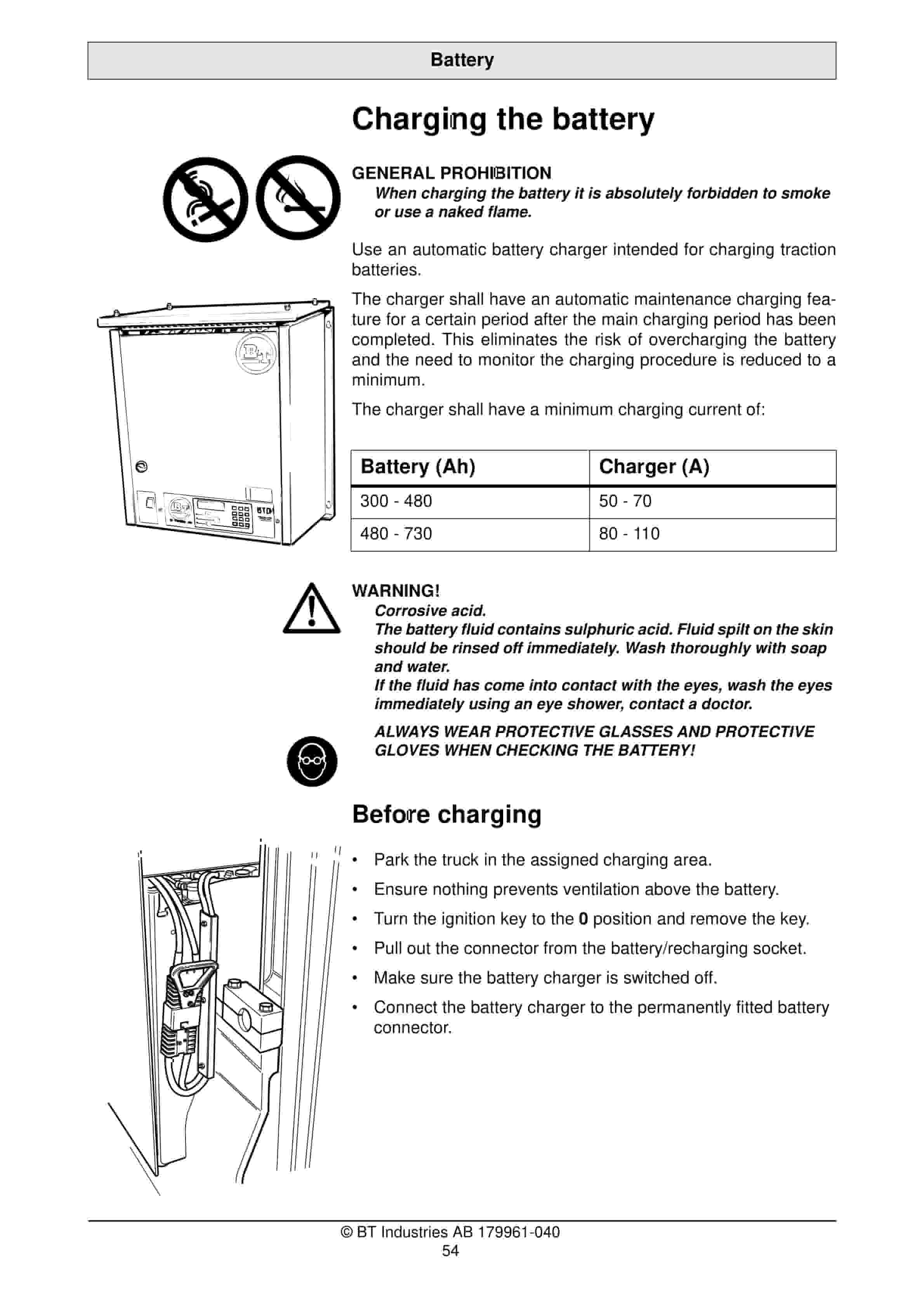
- 10.2. Charging the battery
- 10.2.1. GENERAL PROHIBITION
- 10.2.2. Battery (Ah)
- 10.2.3. Charger (A)
- 10.2.4. Before charging
- 10.2.5. During charging
- 10.2.6. After charging
- 10.3. Battery maintenance
- 10.3.1. WARNING
- 10.3.2. Each week
- 10.3.3. Each month
- 11. Daily service and function checks
- 11.1. WARNING
- 11.2. Pos no.
- 11.3. Check points
- 12. Maintenance
- 12.1. Safety regulations with maintenance work
- 12.1.1. WARNING
- 12.1.2. WARNING
- 12.1.3. WARNING
- 12.1.4. CAUTION
- 12.1.5. WARNING
- 12.2. Maintenance work that is to be carried out by the operator
- 12.3. Maintenance work that may be carried out by trained maintenance personnel
- 12.4. Other service and repair work.
- 12.5. Cleaning and washing
- 12.5.1. External cleaning
- 12.5.2. Cleaning the motor compartment
- 12.5.3. Electrical components
- 12.6. Maintenance chart
- 12.6.1. Pos. no.
- 12.6.2. Work to carry out
- 12.7. Oil and grease specification
- 12.7.1. Lubricant
- 12.7.2. Specification
- 12.7.3. Application area
- 12.7.4. > – 15C
- 12.7.5. < – 15C
- 13. Transporting and storing the truck
- 13.1. The trucks dimensions and weight as standard
- 13.1.1. The trucks dimensions and weight
- 13.2. Lifting the truck
- 13.2.1. WARNING
- 13.2.2. WARNING
- 13.3. Towing and transporting a defective truck
- 13.3.1. WARNING
- 13.3.2. Character
- 13.3.3. Symbol on the switch
- 13.3.4. Function
- 13.4. Storing the truck
- 13.4.1. Battery
- 13.4.2. Hydraulic system
- 13.4.3. Drive unit
- 13.5. Starting after a period of disuse
- 14. Recycling/discarding
- 14.1. Discarding the battery
- 14.2. Scrapping the truck
- 14.2.1. Chassis
- 14.2.2. Hydraulic system
- 14.2.3. Electrical system
Related products
-
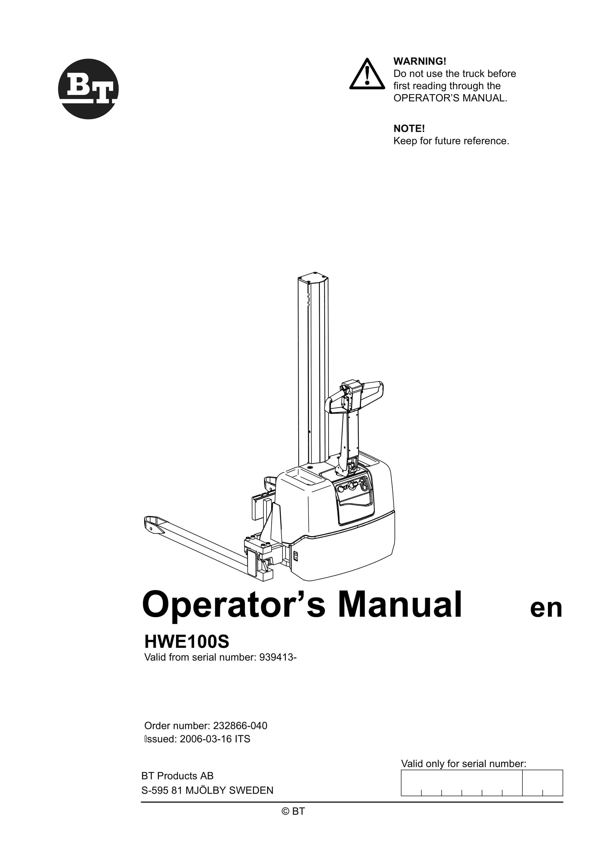
BT HWE100S Operator Manual 232866-040
$30.00 Add to cart -
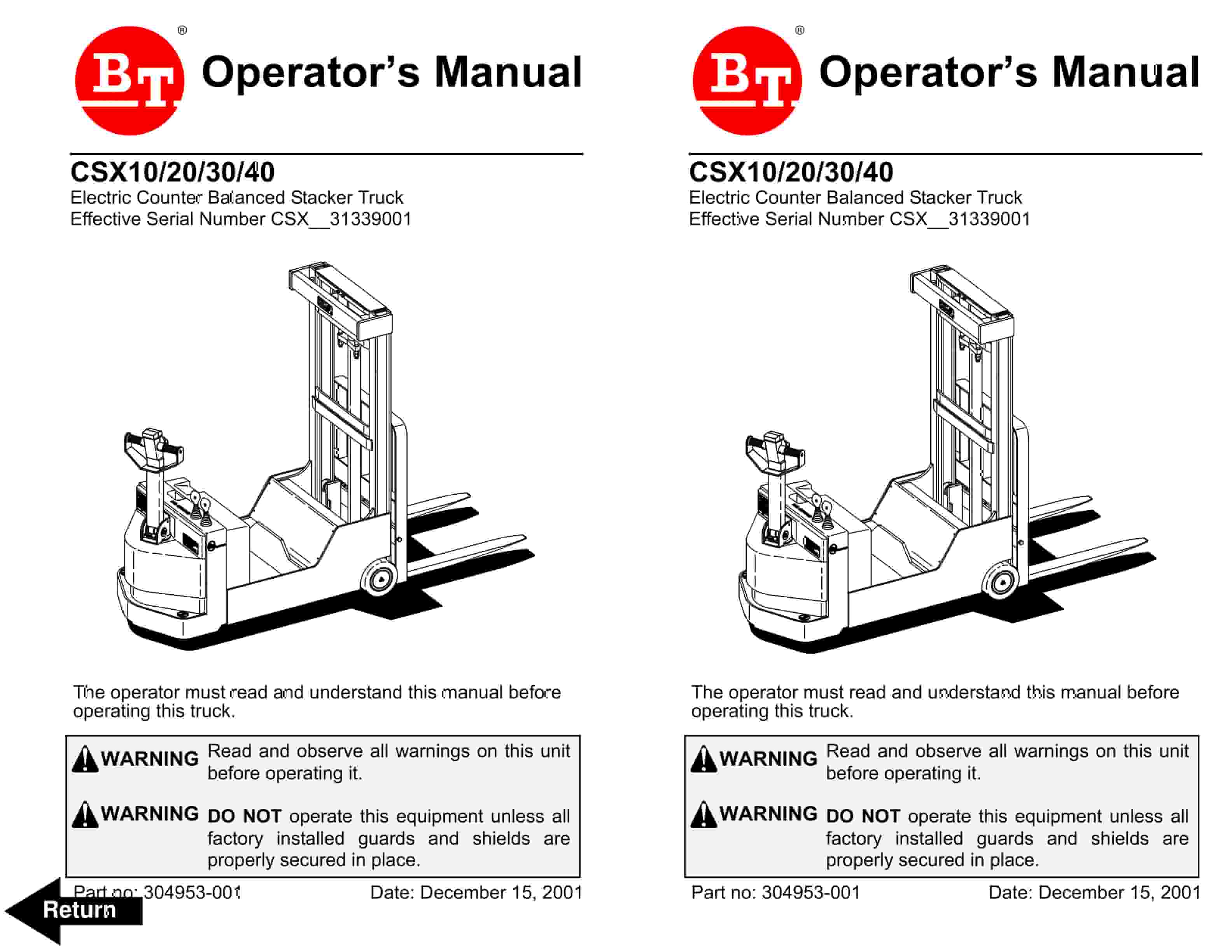
BT CSX Electric Counter Balanced Stacker Truck Operator Manual 304953-001
$30.00 Add to cart -
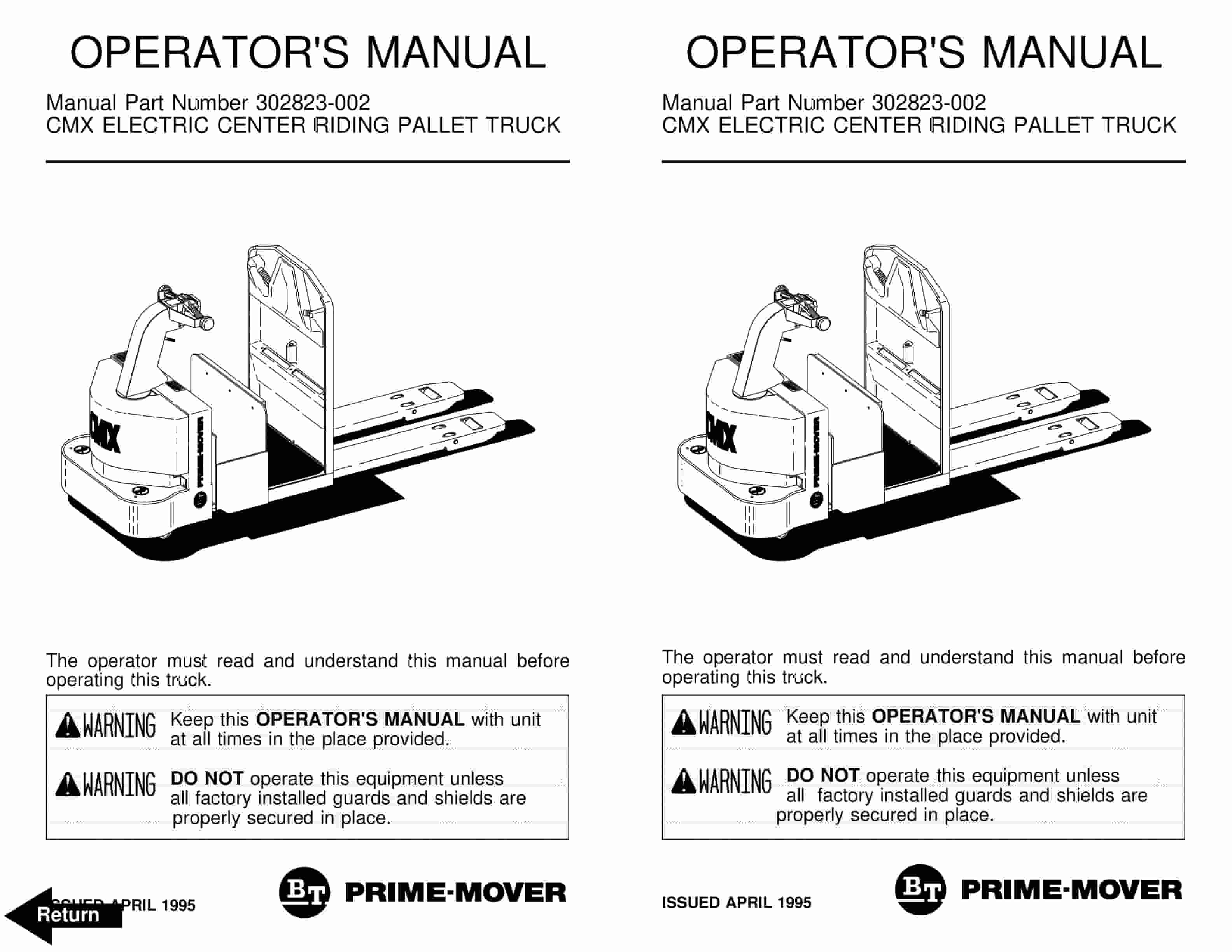
BT CMX Electric Center Riding Pallet Truck Operator Manual 302823-002
$30.00 Add to cart -
BT HX-65 Electric Low Lift Pallet Truck Operator Manual 301385-001
$30.00 Add to cart -
BT HX-80 Electric Low Lift Pallet Truck Operator Manual 301386-000
$30.00 Add to cart


