


BT SPE120XR, SPE120XRD Repair Manual 7550623-040
$30.00
- Type Of Manual: Repair Manual
- Manual ID: 7550623-040
- : Service Manual PDF
- Number of Pages: 300
- Size: 13.7MB
- Format: PDF
Product details
-
Model List:
- SPE120XR, SPE120XRD
- 1. Index
- 2. General introduction
- 2.1. How to use this manual
- 2.2. Warning symbols
- 2.3. Pictograms
- 2.3.1. Screws/Nuts
- 2.3.2. Other pictograms
- 3. General safety rules
- 3.1. Work safety
- 3.2. Electrical systems
- 3.3. Safe lifting
- 3.4. Truck modifications
- 4. Operation and connection sequences
- 4.1. Description of functions
- 4.1.1. Operating principle
- 5. Parameters
- 5.1. Parameter settings
- 5.1.1. General
- 5.1.2. Show parameters CAN key not connected
- 5.1.3. Show the parameters CAN key connected
- 5.1.4. Setting operator parameters
- 5.1.5. Setting the service parameters
- 5.1.6. Summary of operator parameters
- 5.1.7. Description of operator parameters
- 5.1.8. Summary of service parameters
- 5.1.9. Description of service parameters
- 5.1.10. Configurable Option parameters
- 6. Installation and commissioning
- 6.1. Transporting the truck
- 6.2. Transporting the mast
- 6.3. Safe lifting
- 6.4. Taking into operation
- 6.4.1. Battery
- 6.4.2. Parameter setting
- 6.4.3. Test driving and checks
- 7. Maintenance
- 7.1. Introduction
- 7.2. Safety precautions for maintenance work
- 7.3. Maintenance instructions
- 7.3.1. Cleaning and washing
- 7.4. Checks for cracks
- 7.4.1. Visual inspection
- 7.4.2. Crack detection
- 7.5. Periodic maintenance
- 7.5.1. Every 500 operating hours/6 m
- 7.5.2. Every 1000 operating hours/12 m
- 7.5.3. Every 3000 operating hours/36 m
- 7.5.4. Lubrication chart
- 8. Troubleshooting methods
- 8.1. Initial troubleshooting
- 8.2. Concluding troubleshooting
- 8.3. Troubleshooting using error codes
- 8.3.1. Error code log
- 8.3.2. Warning codes
- 8.3.3. Error codes
- 8.3.4. Transistor regulator error codes
- 8.4. Auxiliary functions
- 8.4.1. Built-in test function
- 8.4.2. Display test mode
- 8.5. Troubleshooting chart
- 8.5.1. The truck cannot be driven
- 8.5.2. The truck can be driven but only at reduced speed
- 8.5.3. The truck can be driven but behaves abnormally
- 8.5.4. Hydraulic system blocked or becomes blocked by a specific operation
- 8.5.5. Hydraulic system operates but behaves abnormally
- 8.5.6. Steering servo error
- 9. Frame/Chassis C0000
- 9.1. Inspection covers C0340
- 9.1.1. Opening the motor compartment
- 9.1.2. Close the motor compartment
- 9.2. Motor suspension C0450
- 9.2.1. Components
- 9.2.2. Removing the motor suspension
- 9.2.3. Spring replacement
- 9.3. Operator platform C0560
- 9.3.1. Components
- 9.3.2. Removing the platform
- 9.3.3. Fitting the operator platform
- 10. Motors C1000 Action
- 10.1. Pump motor C1710
- 10.1.1. Replacing the pump motor
- 10.2. Drive motor, C1760
- 10.2.1. Overview
- 10.2.2. Removing the drive motor
- 10.2.3. Fastening the drive motor
- 10.2.4. Disassembling the drive motor
- 10.2.5. Assembling the drive motor
- 10.2.6. Cleaning
- 11. Drive gear C2000
- 11.1. Drive gear C2000
- 11.2. Overview
- 11.3. Removing the drive gear from the truck
- 11.4. Installing the drive gear in the truck
- 11.5. Oil check or change
- 11.5.1. Checking/refilling the oil
- 11.5.2. Oil change
- 11.6. Replacing the drive shaft seal
- 11.6.1. Dismantling
- 11.6.2. Installation
- 11.7. Leakage from top cover
- 12. Brakes and wheels C3000
- 12.1. Parking brake C3370
- 12.1.1. Overview
- 12.1.2. Maintenance
- 12.2. Drive wheel C3530
- 12.2.1. Replacing the drive wheel
- 12.3. Support/castor wheels – 3540
- 12.3.1. Components
- 12.3.2. Replacing the castor wheel
- 12.4. Support arm wheel – 3550
- 12.4.1. Component overview
- 12.4.2. Replacing the wheel
- 13. Steering system C4000
- 13.1. Tiller arm handle C4110
- 13.1.1. Tiller arm handle components
- 13.1.2. Disassembling/assembling the steering unit handle
- 13.1.3. Replacing the signal button/switch
- 13.1.4. Replacement of lift/lower button
- 13.1.5. Replacing the lift control for simultaneous lift
- 13.2. Electric steering servo C4300
- 13.2.1. General
- 13.2.2. Component parts, steering servo
- 13.3. Adjustment
- 13.3.1. Reference sensor.
- 13.3.2. Calibration
- 13.4. Replacing the steering angle potentiometer
- 14. Electrical system C5000
- 14.1. General
- 14.1.1. Terminology
- 14.1.2. Version numbers
- 14.1.3. Description of steering system
- 14.1.4. Spider expansion unit (SEU)
- 14.1.5. Speed limitation
- 14.1.6. Hour meter and battery charge level
- 14.1.7. Reset voltage for BDI
- 14.1.8. TLS – Truck log system (optional)
- 14.1.9. ID unit (optional)
- 14.1.10. Warning lamp
- 14.2. Transistor regulator
- 14.2.1. General
- 14.2.2. Technical specifications Curtis 1243
- 14.3. Sending units and sensors C5800
- 14.3.1. Inductive sensors
- 14.4. Electrical system C5000
- 14.5. Battery C5110
- 14.5.1. Battery recommendations
- 14.5.2. Changing the battery
- 14.6. Senders and sensors C5380
- 14.6.1. Replacing the position sensor with 1.8 m XR/XRD
- 14.6.2. Replacing the position sensor for the secondary lift
- 14.6.3. Adjusting the sensor for the secondary lift
- 14.6.4. Replacing the reference sensor for the steering servo
- 15. Hydraulic system C6000
- 15.1. System description
- 15.1.1. Simultaneous lift (main lift and secondary lift)
- 15.1.2. Main lift
- 15.1.3. Working pressure
- 15.1.4. PowerTrak system
- 15.2. Hydraulic unit C6100
- 15.2.1. Overview SPE120 XRD
- 15.2.2. Tightening torque for hydraulic unit
- 15.3. Installation instructions, hydraulic hoses SPE120 XRD
- 15.3.1. Overview SPE120 XR
- 15.4. Main valve C6210
- 15.4.1. Pressure limiting valve
- 15.4.2. Pressure sensor
- 15.5. Hose rupture valve
- 15.6. Hydraulic system C6000
- 15.7. Hydraulic hygiene
- 15.7.1. Washing
- 15.7.2. Packaging
- 15.7.3. Handling
- 15.7.4. Storage
- 15.7.5. Work procedures
- 15.7.6. Emptying the tank
- 15.7.7. Filling the tank
- 15.7.8. Removing/installing the hydraulic unit
- 15.7.9. Replacing the tank
- 15.7.10. Replacing the oil pump
- 15.7.11. Bleeding the hydraulic system
- 15.8. Main valve C6210
- 15.8.1. Replacing the main valve
- 15.8.2. Replacing the valve
- 15.8.3. Replacing the valve solenoid
- 15.8.4. Replacing pressure filter PF SPE120XRD
- 15.8.5. Quick change connector
- 15.9. Main lift C6610
- 15.9.1. Removing lift cylinder from the mast
- 15.9.2. Assembling the cylinder in the mast
- 15.10. Lift cylinder secondary mast C6670
- 16. Mast/Lift system C7000
- 16.1. Main mast C7100
- 16.1.1. Replacing/removing mast XRD
- 16.1.2. Replacement/installation of the mast
- 16.1.3. Replacing/fitting the fork yoke
- 16.1.4. Adjusting the mast inclination
- 16.2. Secondary mast C7200
- 16.2.1. Removing the secondary mast/cylinder
- 16.2.2. Installing the secondary mast/cylinder
- 16.2.3. Adjusting and shimming the secondary mast.
- 16.3. Main lift chain system C1720
- 16.3.1. Check
- 16.3.2. Lubrication
- 16.3.3. Adjustment
- 16.3.4. Replacing the chain
- 16.4. Forks C7410
- 16.4.1. Overview
- 16.4.2. Forks, repairs and testing
- 17. Options 9000
- 17.1. Component overview, T.W.I.S. (Toyota Wireless Information System)
- 17.2. DC/DC converter
- 17.2.1. Installation of the DC/DC converter and 12 V socket
- 17.2.2. Wiring diagram, DC/DC converter
- 18. Instructions for disposal
- 18.1. General
- 18.2. Marking of plastics
- 18.2.1. General marking of products and packaging
- 18.2.2. Marking according to the manufacturers standards
- 18.3. Pressure vessels
- 18.3.1. Gas dampers
- 18.4. Sorting categories
- 19. Wiring diagram
- 19.1. Overview of electrical equipment
- 19.1.1. Component location
- 19.1.2. Component list
- 19.2. List of symbols
- 19.3. Overview
- 19.4. Wiring diagrams
- 20. Hydraulics schematics
- 20.1. SPE120XRD
- 20.1.1. Hydraulic pump
- 20.1.2. Reach
- 20.2. SPE120XR
- 20.3. Hydraulic pump
- 20.3.1. Reach
- 21. Tools
- 21.1. AMP connectors
- 21.2. AMP connectors, Multilock series 040
- 21.3. Super Seal connectors
- 21.4. Molex connectors
- 21.5. Other tools
- 22. Service data and grease specifications
- 22.1. General tightening torques
- 22.1.1. Galvanised, non-oiled screws
- 22.1.2. Untreated, oiled screws
- 22.2. Oil and grease specification
- 23. Technical data
Related products
-
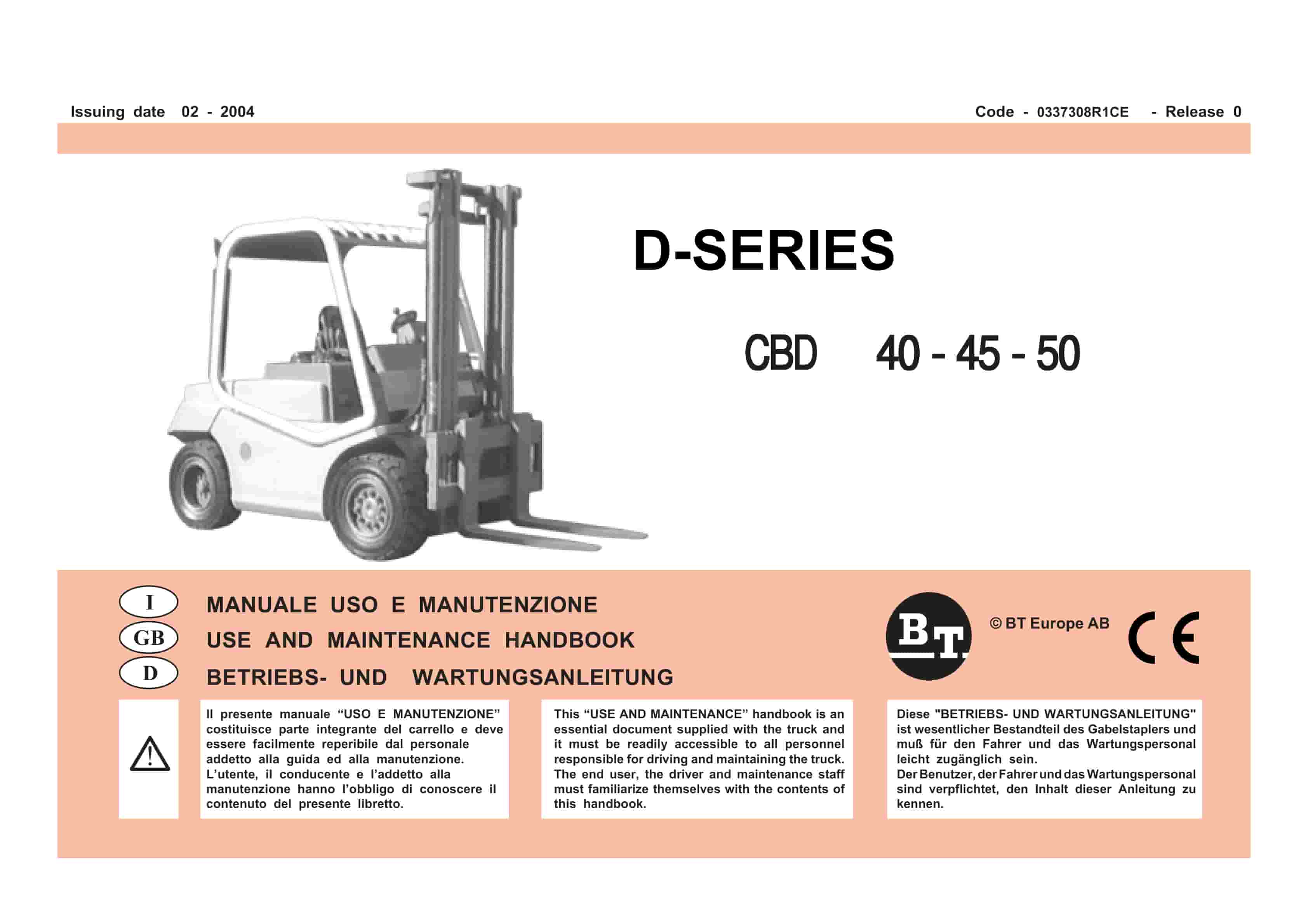
BT D-Series CBD40, CBD45, CBD50 Use And Maintenance Handbook 0337308R1CE
$30.00 Add to cart -
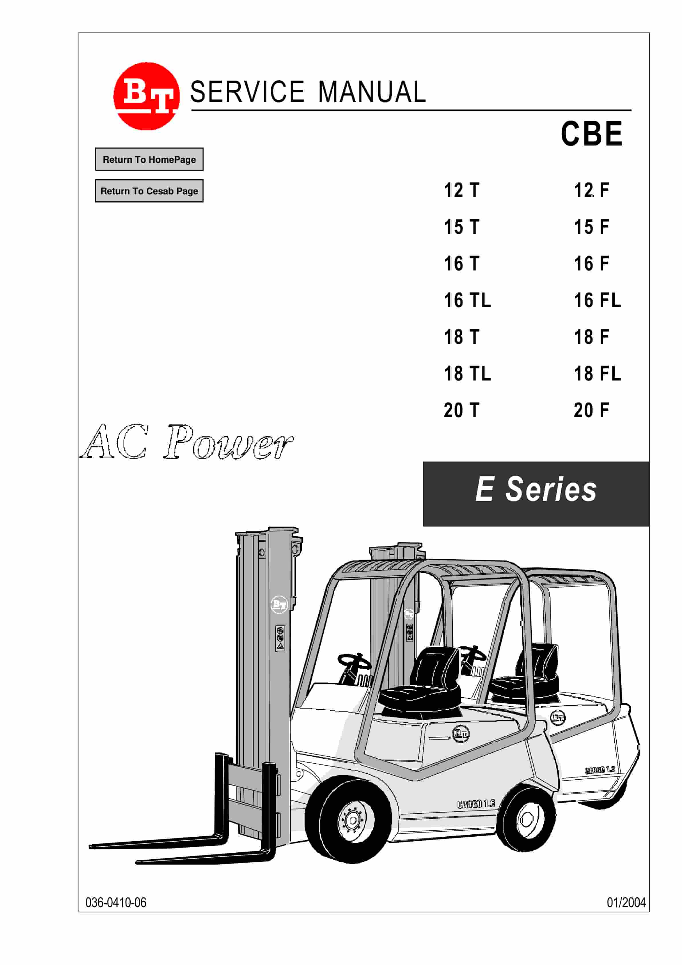
BT CBE 12T to CBE 20F Service Manual 036-0410-06
$30.00 Add to cart -
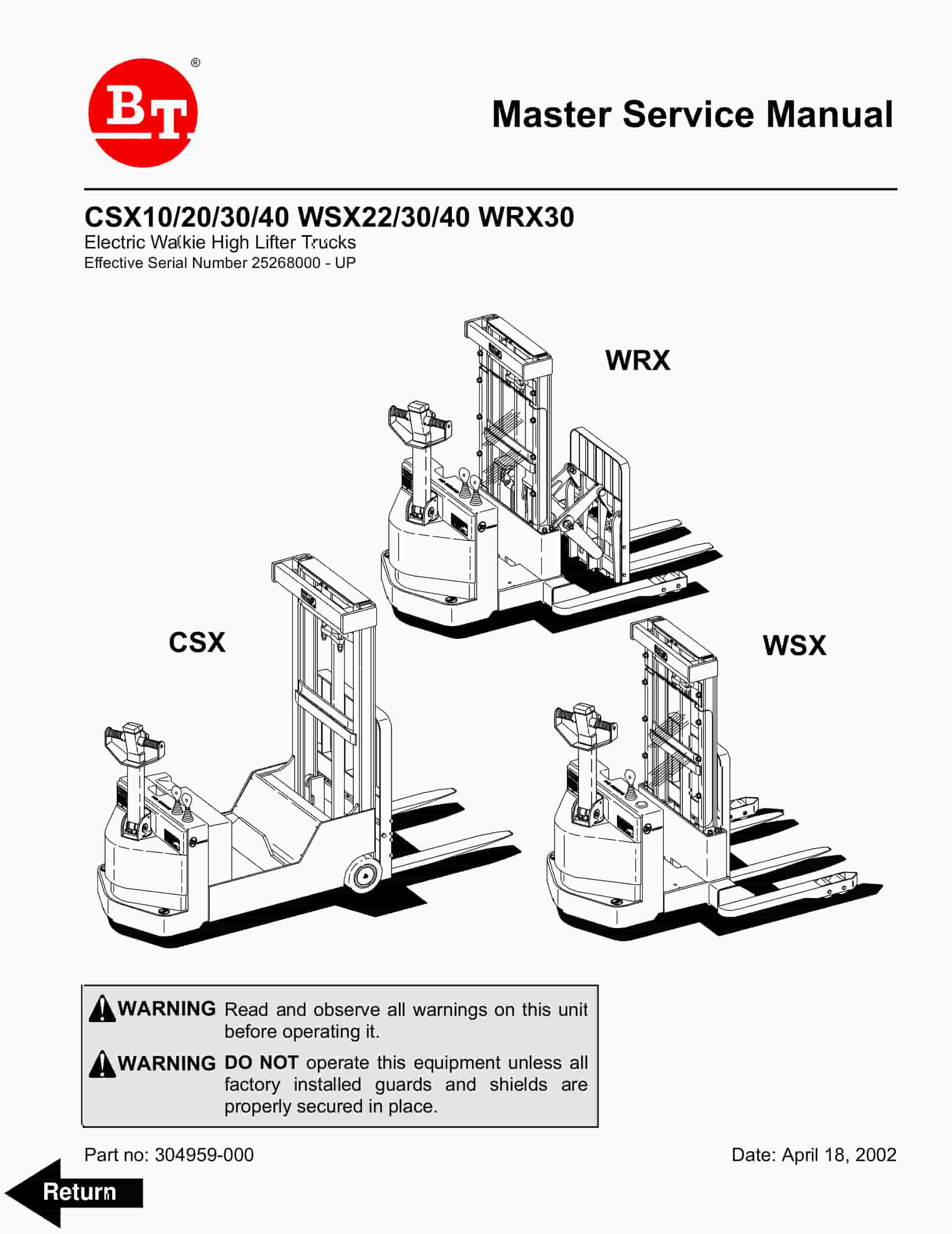
BT CSX10, CSX20, CSX30, CSX40, WSX22, WSX30, WSX40, WRX30 Electric Walkie High Lifter Truck Service Manual 304959-000
$30.00 Add to cart -
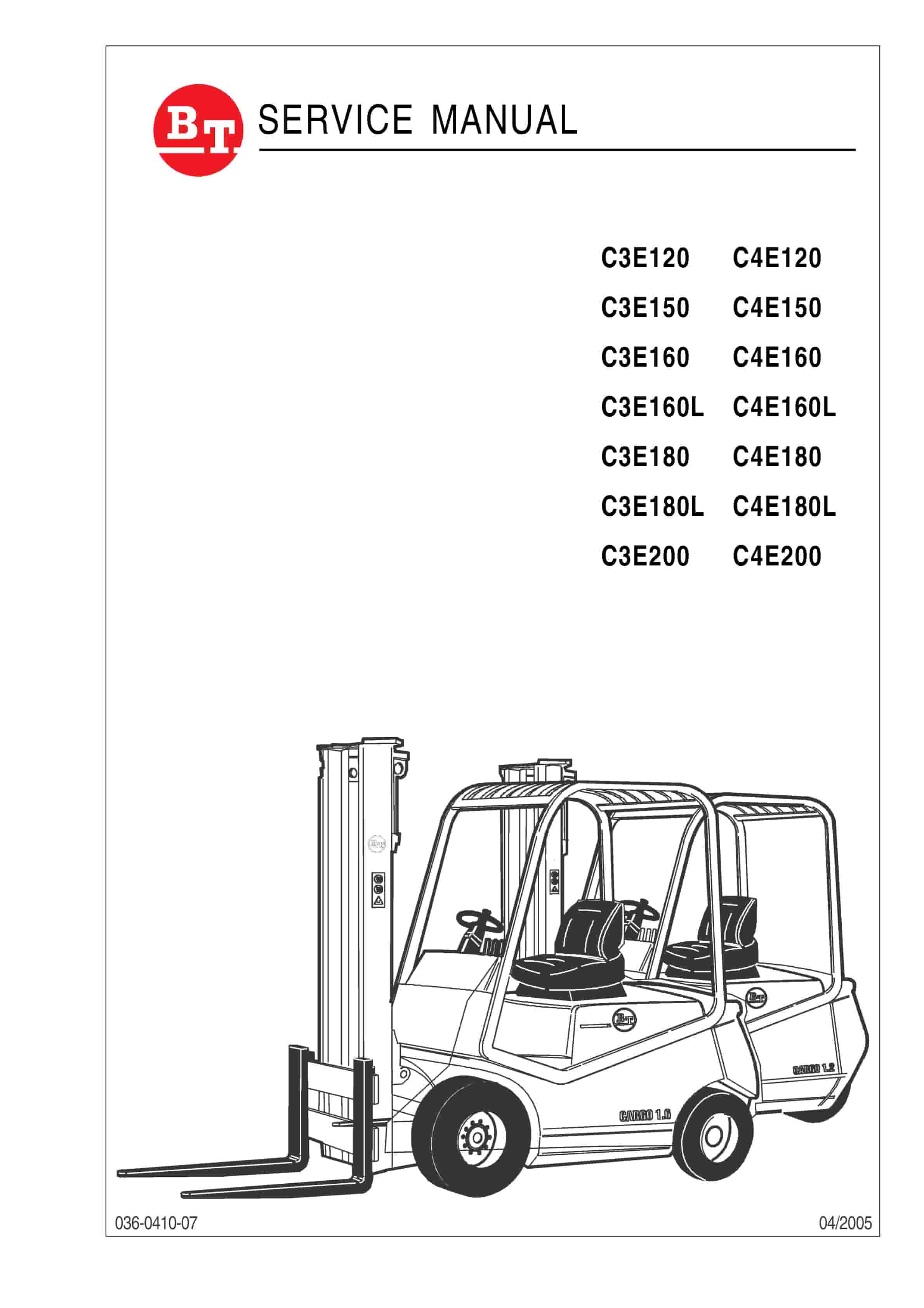
BT C3E120 to C4E200 Service Manual 036-0410-07
$30.00 Add to cart -
BT C3E120 to C4E200 Use And Maintenance Handbook 0337383R1CE
$30.00 Add to cart