

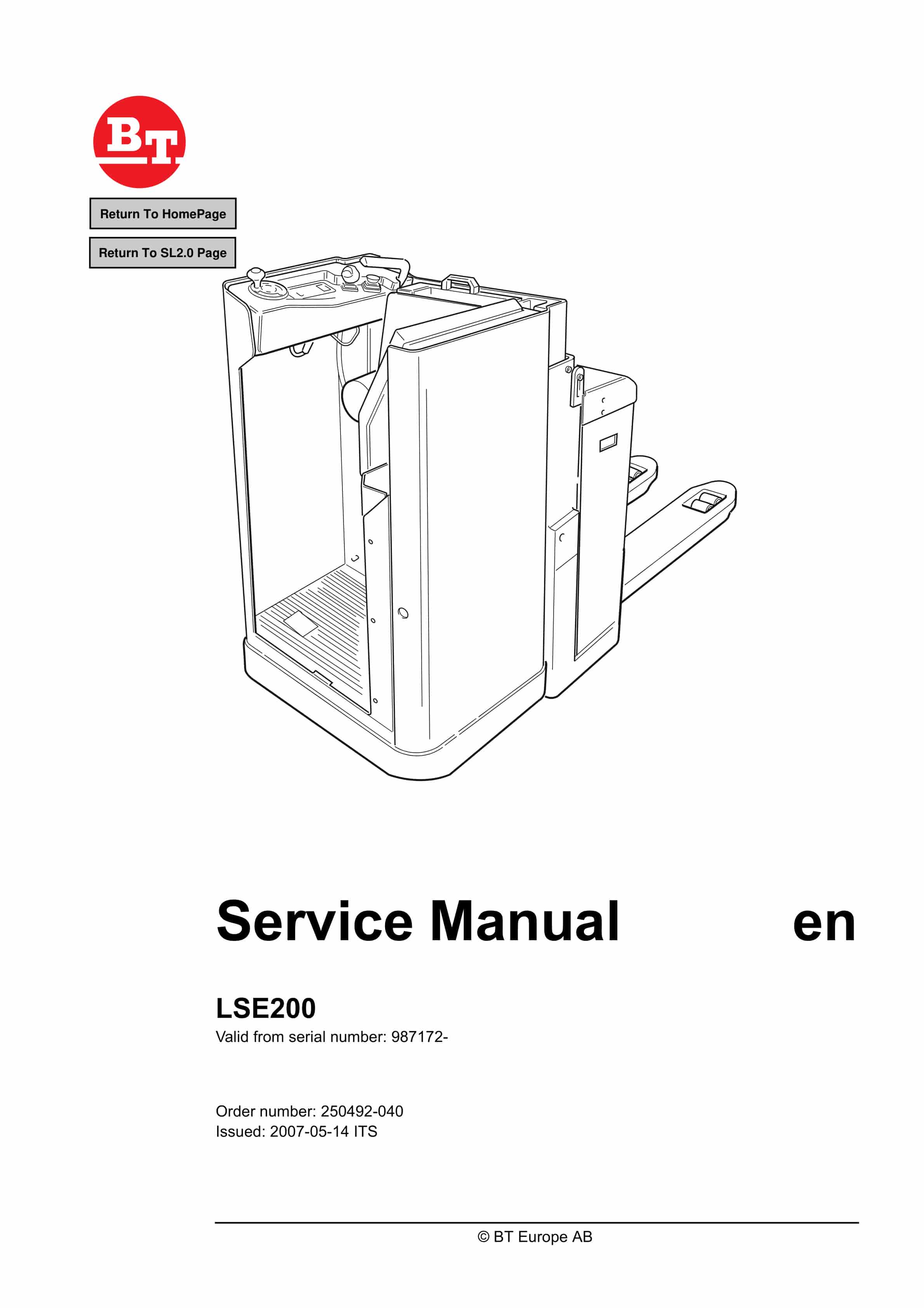
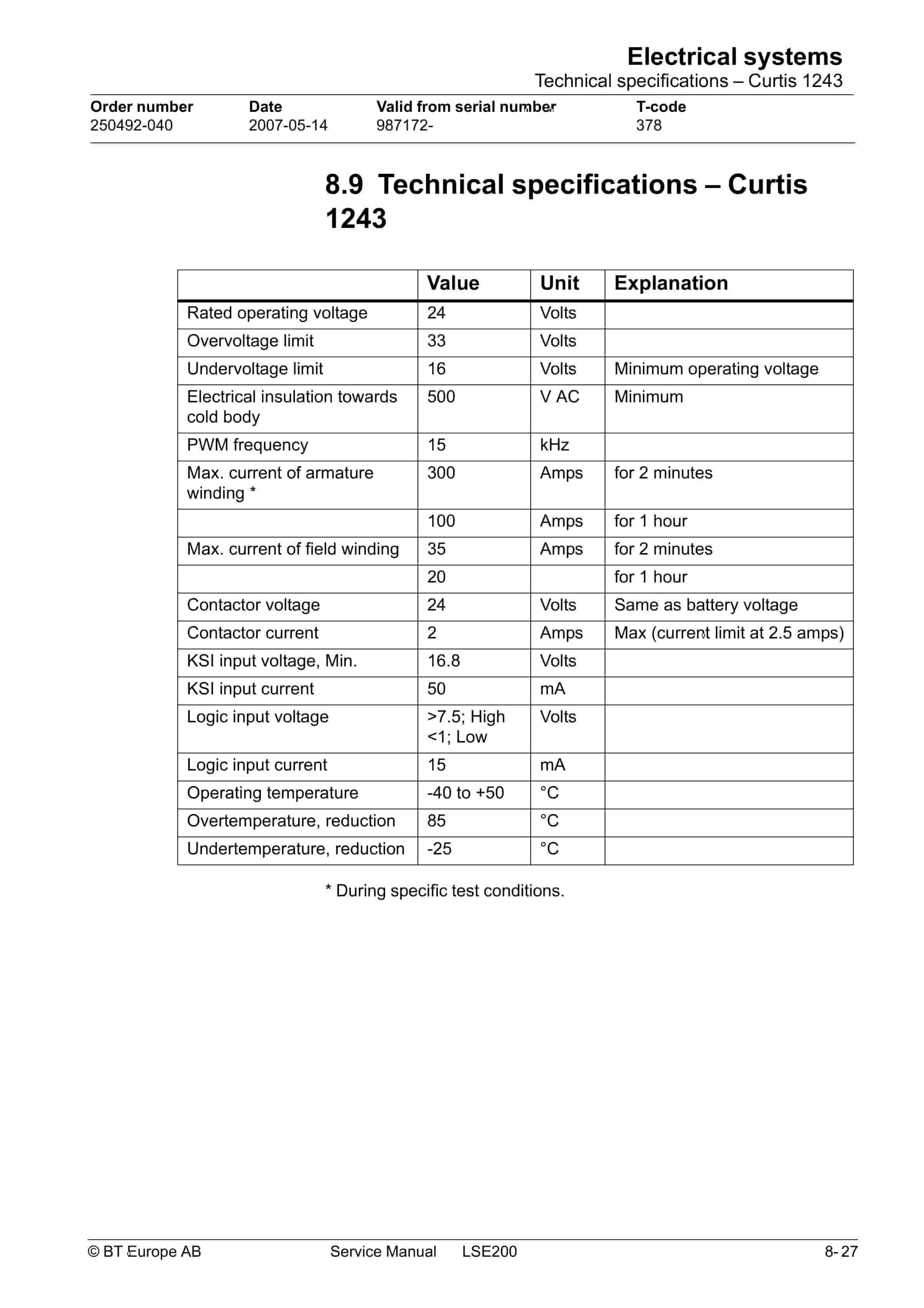
BT LSE200 Service Manual 250492-040
$30.00
- Type Of Manual: Service Manual
- Manual ID: 250492-040
- : Service Manual PDF
- Number of Pages: 96
- Size: 3.4MB
- Format: PDF
Product details
-
Model List:
- LSE200
- 1. Table of Contents
- 2. Technical Data
- 2.1. General tightening torques
- 2.1.1. Galvanised, non-oiled bolts
- 2.1.2. Untreated, oiled bolts
- 3. Maintenance
- 3.1. Safety regulations with maintenance work
- 3.2. Cleaning and washing
- 3.2.1. External cleaning
- 3.2.2. Cleaning the motor compartment
- 3.2.3. Electrical components
- 3.3. Safe lifting of the truck
- 3.4. Maintenance schedule
- 3.5. Lubrication chart
- 3.6. Oil and grease specification
- 4. Tools
- 4.1. Super Seal connectors
- 4.2. AMP connectors
- 4.2.1. AMP Connectors, 040 series
- 4.3. Molex connectors
- 4.4. Grease guns
- 4.5. Other tools
- 5. Electric Drive Motor – 1700
- 5.1. General
- 5.2. Mechanical construction
- 5.2.1. Special tools
- 5.3. Dismantling/fitting
- 5.3.1. Removing the motor from the truck
- 5.3.2. Fitting the motor in the truck
- 5.4. Service and Repairs
- 5.4.1. Cleaning
- 5.4.2. Dismantling the motor
- 5.4.3. Reassembling the motor
- 5.4.4. Armature bearings
- 5.4.5. Replacing the drive end bearing
- 5.4.6. Replacing the commutator end bearing
- 5.4.7. Carbon brushes and brush holders
- 5.4.8. Replacing carbon brushes
- 5.4.9. Commutator
- 5.4.9.1. Machining the commutator
- 5.5. Storage/Transport
- 5.5.1. Storage
- 5.6. Data
- 6. Drive/Transmission Assembly – 2550
- 6.1. General
- 6.2. Component parts
- 6.3. Dismantling the drive assembly from the truck
- 6.4. Refitting the drive assembly in the truck
- 6.5. Oil check after oil change
- 6.5.1. Checking/refilling the oil
- 6.5.2. Changing the oil
- 6.6. Replacing the gasket
- 6.6.1. Dismantling
- 6.6.2. Assembly
- 6.7. Leakage from the upper cover
- 6.8. Replacing the stud
- 7. Electro magnetic brake – 3300
- 7.1. General description
- 7.2. Main components of the brake
- 7.3. Maintenance
- 7.4. Adjustment of gap
- 7.4.1. Adjustment procedure
- 7.5. Optimising the brake system
- 7.5.1. Adjusting the change between the brake stages
- 7.5.1.1. If switching at a higher load is required proceed as follows
- 7.5.1.2. If switching at a lower load is required proceed as follows
- 7.5.2. Adjusting of the first brake stage
- 7.5.3. Adjusting of the second brake stage
- 7.6. Exchange of brake disc
- 8. Electrical systems
- 8.1. Electrical parts
- 8.2. Component List
- 8.3. Electrical wiring diagram
- 8.3.1. Symbol list
- 8.3.2. Electrical wiring diagram (1/5)
- 8.3.3. Electrical wiring diagram (2/5)
- 8.3.4. Electrical wiring diagram (3/5)
- 8.3.5. Electrical wiring diagram (4/5)
- 8.3.6. Electrical wiring diagram (5/5)
- 8.4. Functional description
- 8.4.1. General
- 8.4.2. Key in position 0
- 8.4.3. Key in position I
- 8.4.4. Driving in the drive wheel direction
- 8.4.5. Driving in the fork direction
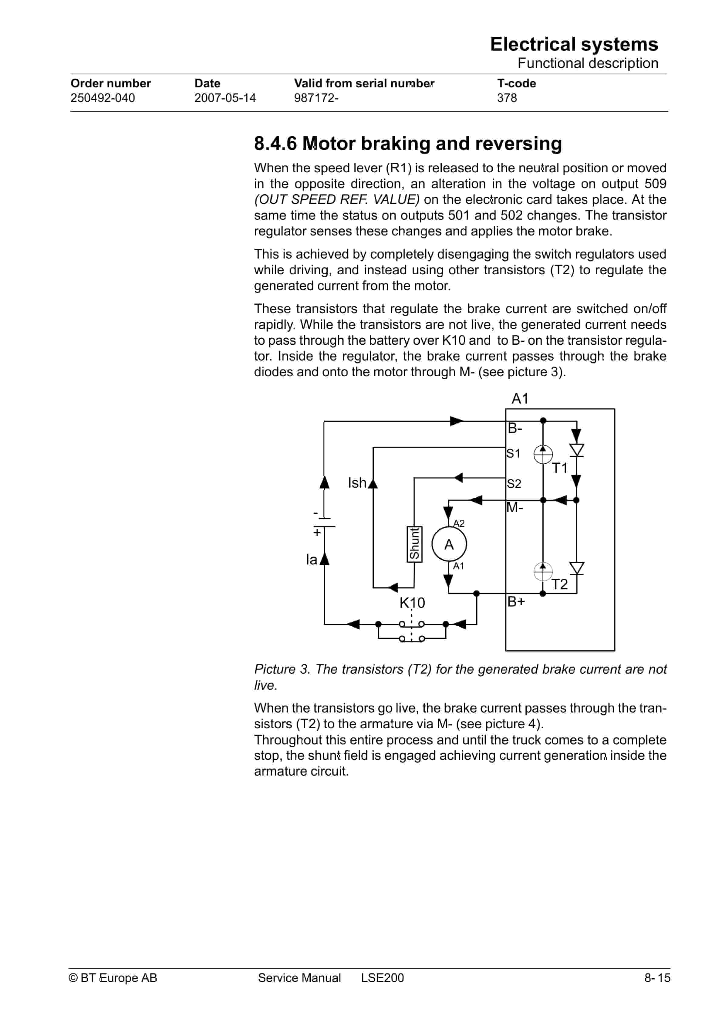
- 8.4.6. Motor braking and reversing
- 8.4.7. Braking
- 8.4.8. Lifting the forks
- 8.4.9. Lowering the forks
- 8.4.10. Horn
- 8.5. Transistor panel
- 8.5.1. General
- 8.5.2. Connectors
- 8.5.3. Logic connector
- 8.6. Parameters
- 8.6.1. Mode 1 and 2
- 8.7. Diagnosing and troubleshooting
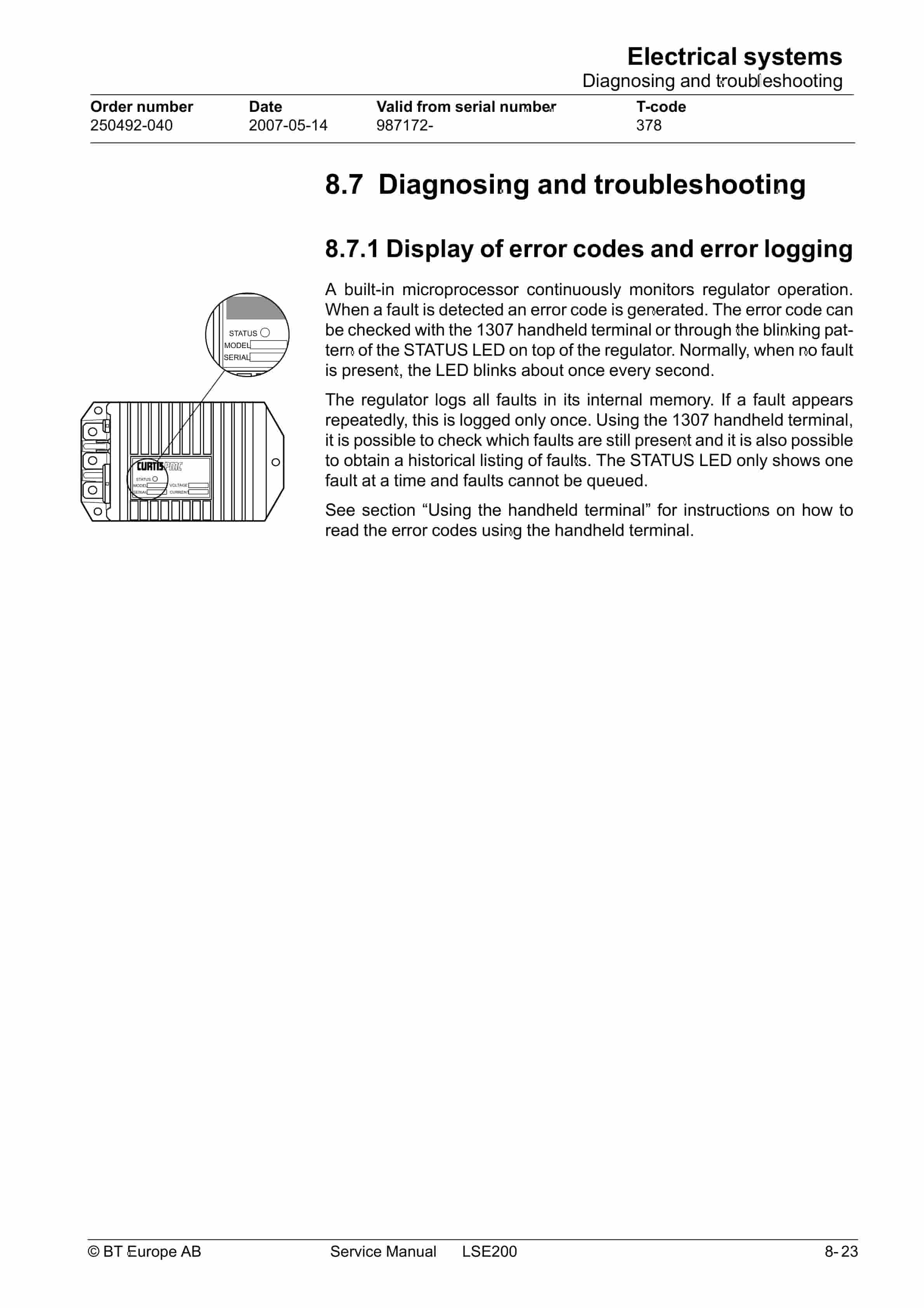
- 8.7.1. Display of error codes and error logging
- 8.7.2. Error codes and troubleshooting
- 8.7.3. Resetting errors
- 8.8. Maintenance
- 8.8.1. Safety
- 8.8.2. Cleaning
- 8.9. Technical specifications – Curtis 1243
- 8.10. Handheld terminal
- 8.11. Using the handheld terminal
- 8.12. Checking and adjusting parameters
- 8.12.1. Using PROGRAM MODE
- 8.12.2. Using MORE INFO in the PROGRAM MODE
- 8.12.3. Using SPECIAL PROGRAM MODE
- 8.12.3.1. Example
- 8.12.4. Using the TEST mode
- 8.12.4.1. Example
- 8.12.5. Using the DIAGNOSTICS MODE
- 8.12.6. SPECIAL DIAGNOSTICS MODE
- 8.13. Electronic card
- 8.13.1. General description
- 8.13.2. Parameter settings
- 8.13.3. Setting the battery size/type
- 8.13.4. Card pin connections and leds
- 8.14. Error codes
- 9. Hydraulic system – 6000
- 9.1. General
- 9.2. Hydraulic diagram
- 9.2.1. Component List
- 9.3. Functional description
- 9.3.1. Lifting the forks
- 9.3.2. Lowering the forks
- 9.3.3. Pressure guard S61
Related products
-
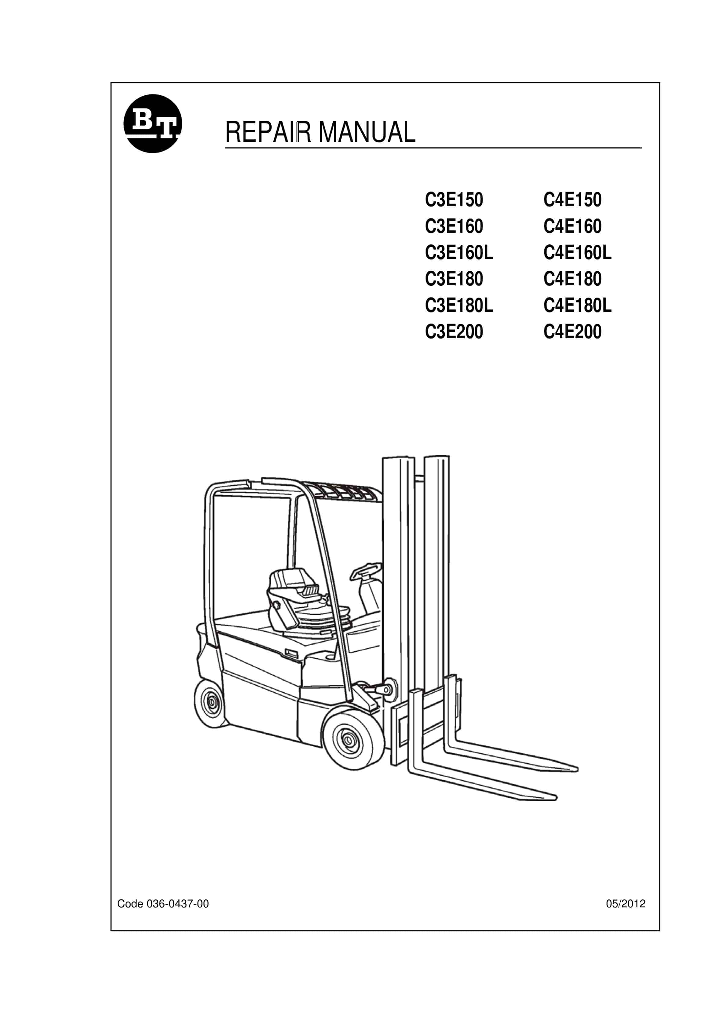
BT C3E150 to C4E200 Repair Manual 036-0437-00
$30.00 Add to cart -
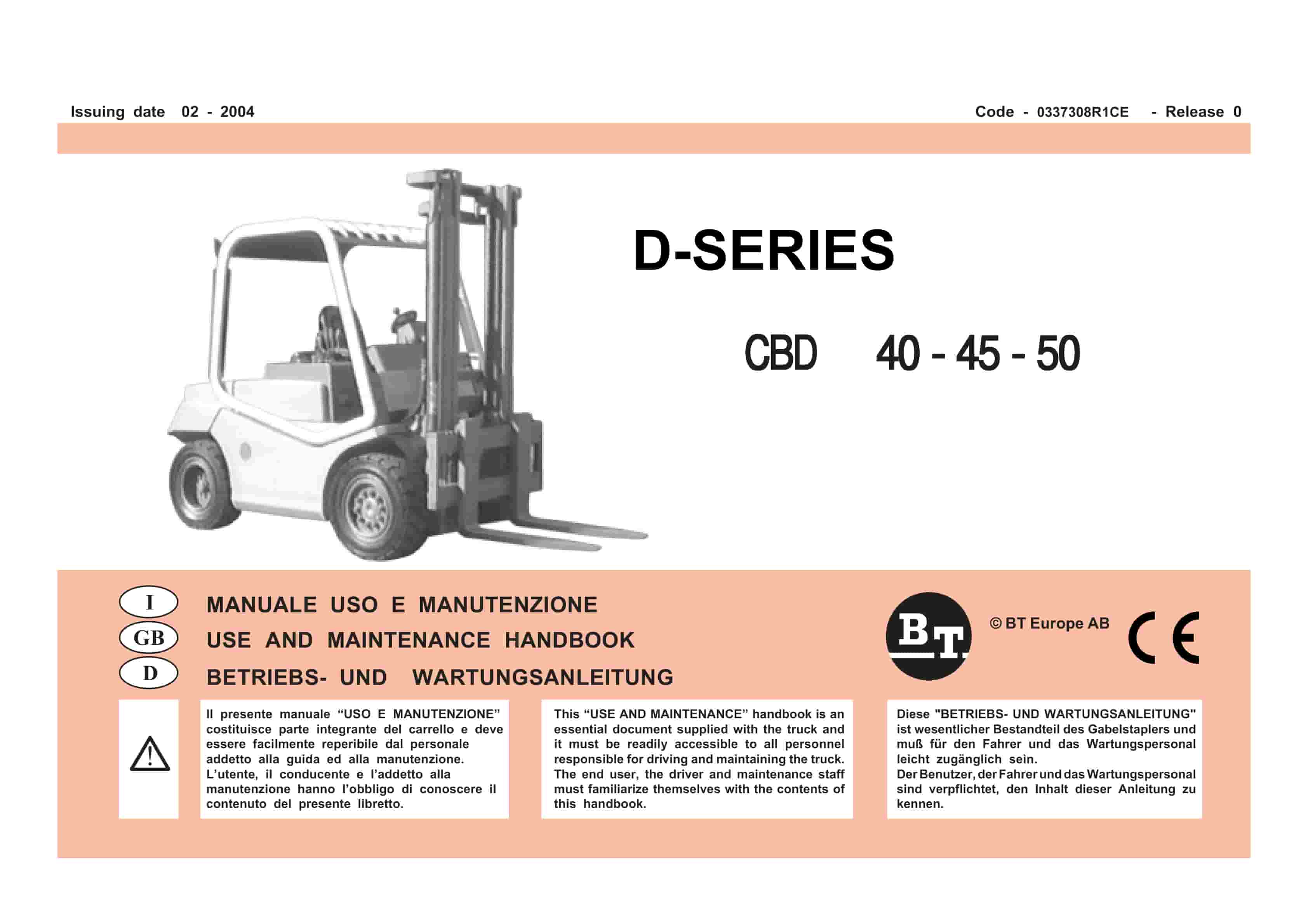
BT D-Series CBD40, CBD45, CBD50 Use And Maintenance Handbook 0337308R1CE
$30.00 Add to cart -
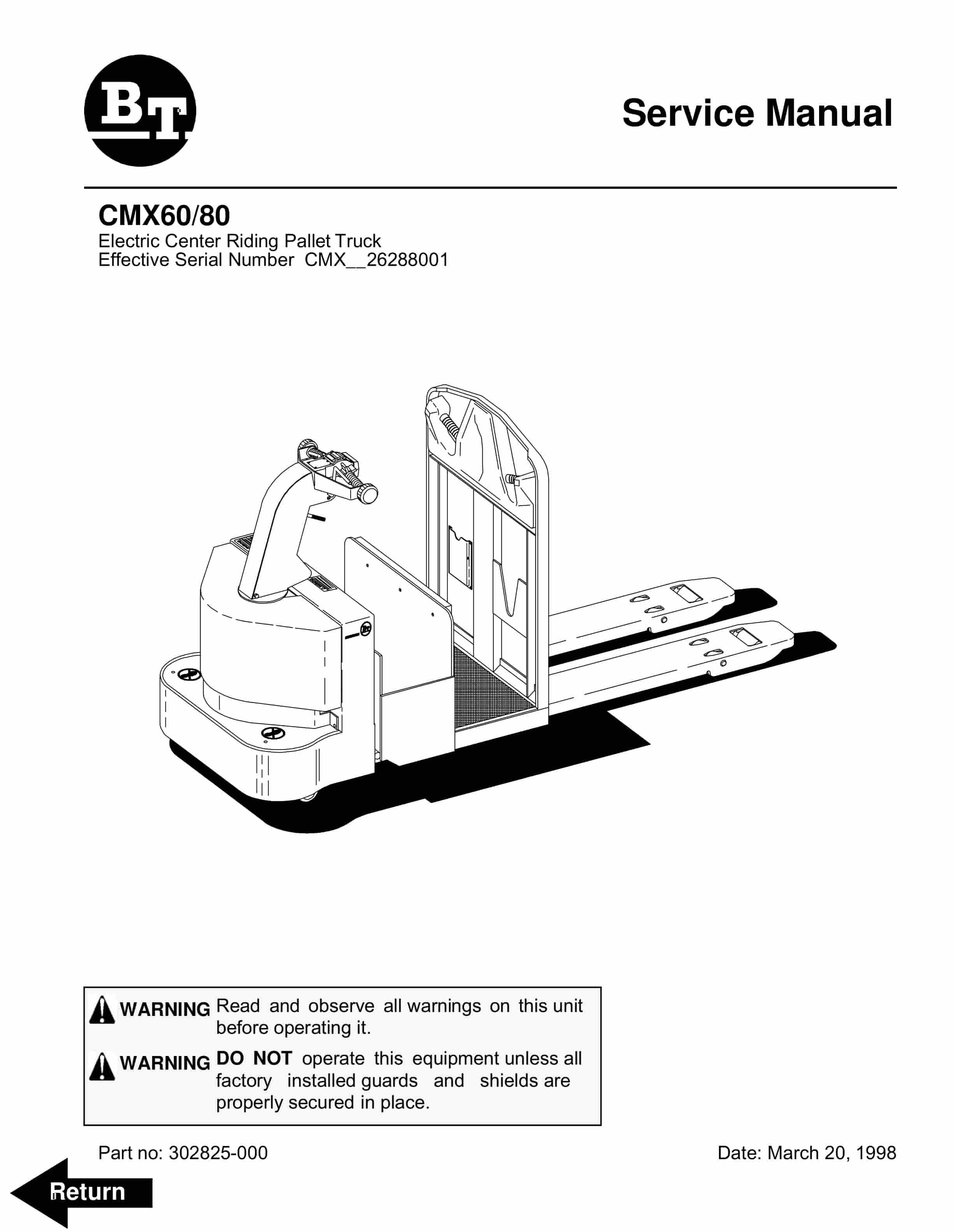
BT CMX60, CMX80 Electric Center Riding Pallet Truck Service Manual 302825-000
$30.00 Add to cart -
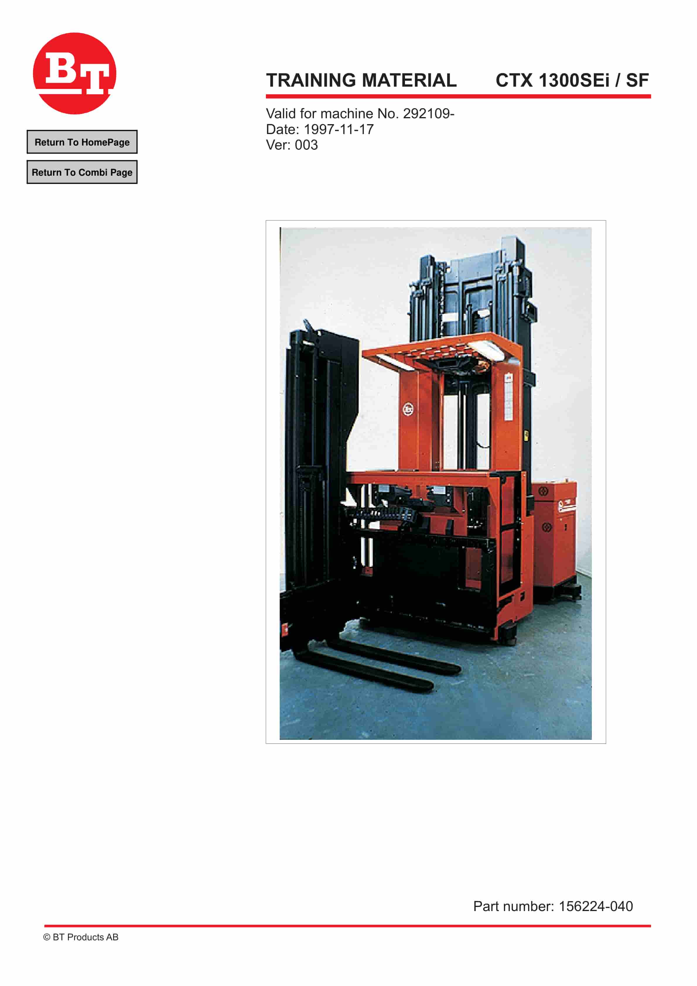
BT CTX 1300SEi, CTX 1300SEi SF Training Material 156224-040
$30.00 Add to cart -
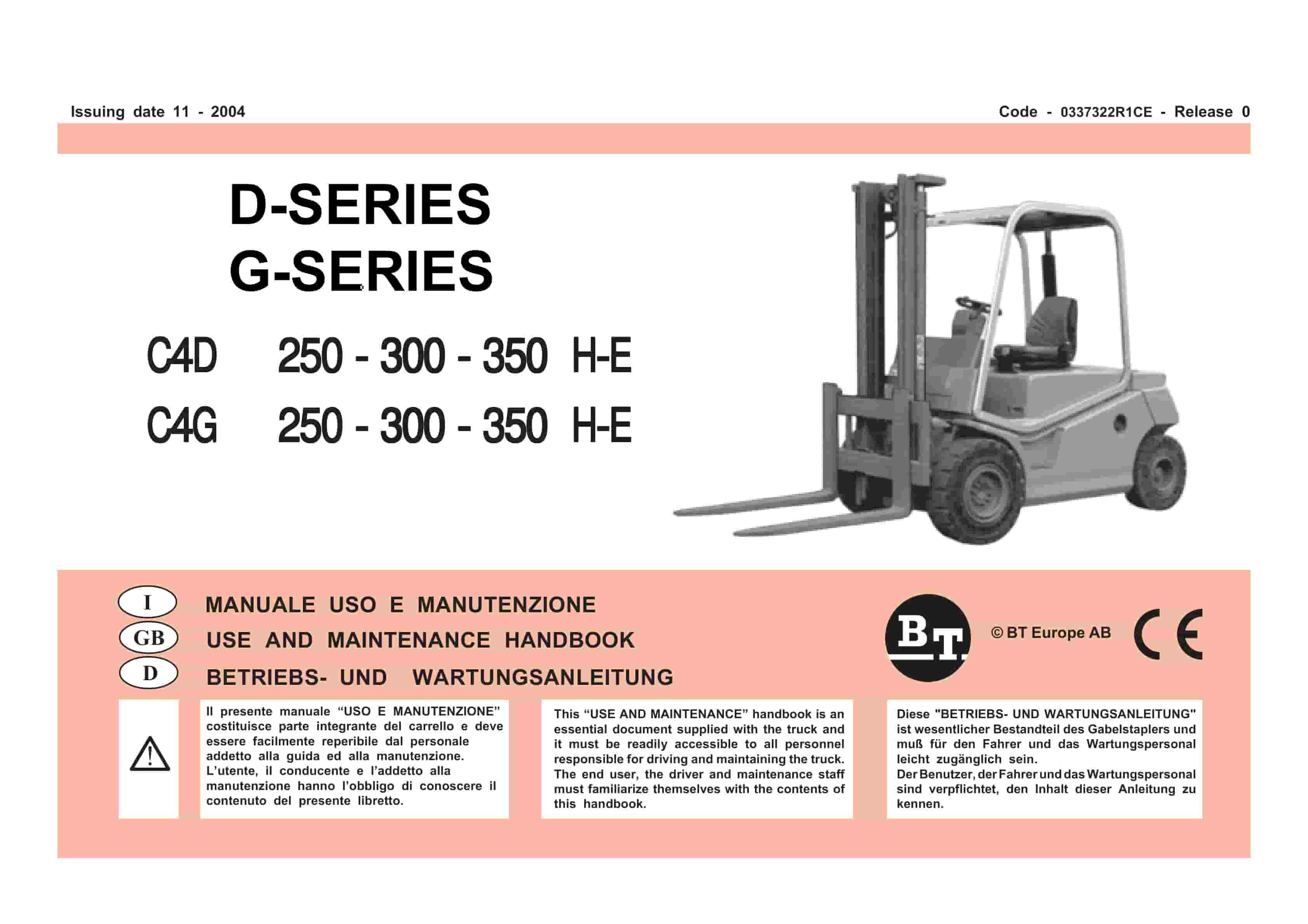
BT D-G-Series C4D250H-E, C4D300H-E, C4D350H-E, C4G250H-E, C4G300H-E, C4G350H-E Use And Maintenance Handbook 0337322R1CE
$30.00 Add to cart


