

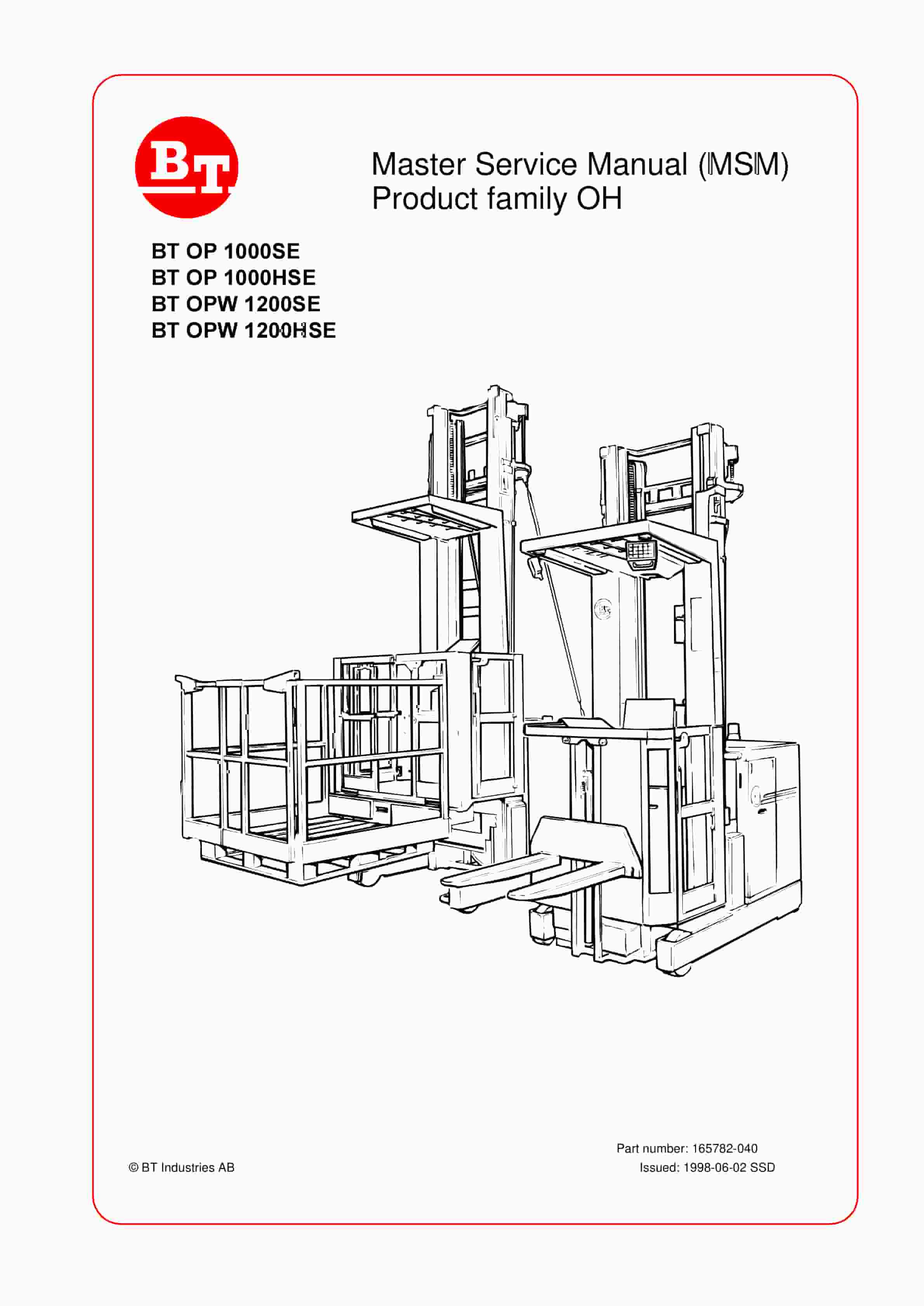
BT OP 1000SE, OP 1000HSE, OPW 1200SE, OPW 1200HSE Service Manual 165782-040
$30.00
- Type Of Manual: Service Manual
- Manual ID: 165782-040
- : Service Manual PDF
- Number of Pages: 201
- Size: 7.7MB
- Format: PDF
Product details
-
Model List:
- OP 1000SE, OP 1000HSE, OPW 1200SE, OPW 1200HSE
- 1. Master Service Manual (MSM) Product family OH
- 1.1. BT OP 1000SE BT OP 1000HSE BT OPW 1200SE BT OPW 1200HSE
- 2. Introduction to BTs Service Manual
- 2.1. Contents Master Service Manual (MSM)
- 2.1.1. Valid from serial number
- 2.1.2. Serial No
- 2.1.3. Document list
- 2.1.3.1. Section
- 2.1.3.2. Document
- 3. M-files.pdf
- 3.1. Contents, M
- 3.1.1. Truck information
- 3.2. m1-175-gb1.pdf
- 3.2.1. Operators manual
- 3.2.1.1. Valid from machine number
- 3.2.1.2. Machine N
- 3.2.1.3. General
- 3.2.1.3.1. Issued operators manuals
- 3.3. m2-175.gb1.pdf
- 3.3.1. General Product Information
- 3.3.1.1. Valid from serial number
- 3.3.1.2. Serial No
- 3.3.1.3. Presentation of the truck
- 3.3.1.3.1. Intended application of the truck
- 3.3.1.3.2. Forbidden application of the truck
- 3.3.1.4. Truck data
- 3.3.1.4.1. Model designation
- 3.3.1.5. Truck dimensions
- 3.3.1.5.1. OP1000SE/OP1000HSE
- 3.3.1.5.2. OPW1200SE/OPW1200HSE
- 3.3.1.6. Identification plate
- 3.3.1.7. Main components
- 3.3.1.7.1. Identification plate With model designation, serial number, year of manufacture, weight witho…
- 3.3.1.7.2. Mast
- 3.3.1.7.3. Emergency lowering valve Valve for emergency lowering under the guard.
- 3.3.1.7.4. Load carrier
- 3.3.1.8. Controls and instruments
- 3.3.1.8.1. OP1000
- 3.3.1.8.2. OPW1200
- 3.3.1.8.3. Control lever OPW with lifting table (accessory)
- 3.4. m4-175.gb1.pdf
- 3.4.1. Technical data
- 3.4.1.1. Valid from serial number
- 3.4.1.2. Serial No.
- 3.4.1.3. OP 1000SE/HSE
- 3.4.1.4. OPW1200SE/HSE
- 3.4.1.4.1. Drive motor
- 3.4.1.4.2. Transmission/gear change
- 3.4.1.4.3. Drive wheel
- 3.4.1.4.4. Support arm wheel
- 3.4.1.4.5. Hydraulic unit, main lift
- 3.4.1.4.6. Hydraulic unit, forks
- 3.4.1.4.7. Batteries
- 3.4.1.4.8. Travel speeds
- 3.4.1.4.9. Lift-/lower speeds
- 3.4.1.4.10. Current usage
- 3.5. m6-gb.pdf
- 3.5.1. Ordering Spare Parts
- 3.6. m7-175.gb1.pdf
- 3.6.1. Quality Parts
- 3.6.1.1. Valid from serial number
- 3.6.1.2. Serial No
- 3.6.1.3. Issued Quality Parts
- 3.6.1.3.1. Order number
- 3.7. m8-175.gb1.pdf
- 3.7.1. Recommended Spare Parts (RSP)
- 3.7.1.1. Valid from serial number
- 3.7.1.2. Serial No
- 3.7.1.3. Issued RSP
- 3.7.1.3.1. Serial no
- 4. P-files.pdf
- 4.1. Content, P
- 4.1.1. Preventive Maintenance
- 4.2. p1-175.gb1.pdf
- 4.2.1. Introduction, maintenance
- 4.2.1.1. Safety regulations with maintenance work
- 4.2.1.1.1. WARNING
- 4.2.1.1.2. WARNING
- 4.2.1.1.3. WARNING
- 4.2.1.1.4. CAUTION
- 4.2.1.2. Cleaning and washing
- 4.2.1.2.1. External cleaning
- 4.2.1.2.2. Cleaning the motor compartment
- 4.2.1.2.3. Electrical components
- 4.2.1.3. Safe lifting
- 4.2.1.3.1. WARNING
- 4.3. p2-175.gb1.pdf
- 4.3.1. Preventive maintenance
- 4.3.1.1. Valid from serial number
- 4.3.1.2. Serial No.
- 4.3.1.3. Maintenance chart
- 4.3.1.3.1. Work to carry out
- 4.4. p3-175.gb1.pdf
- 4.4.1. Oil and grease specification
- 4.4.1.1. Valid from serial number
- 4.4.1.2. Serial No
- 4.4.1.3. Lubricant
- 4.4.1.4. Specification
- 4.4.1.5. > – 15C
- 4.4.1.6. < – 15C
- 5. S-files.pdf
- 5.1. Content, S
- 5.1.1. Service instructions
- 5.2. gb1.pdf
- 5.2.1. Transmission, Gear
- 5.2.1.1. Valid from serial number
- 5.2.1.2. Serial No
- 5.2.1.3. General
- 5.2.1.4. Gear components/data
- 5.2.1.4.1. Component identification
- 5.2.1.4.2. Technical gear data
- 5.2.1.4.3. Dismantled gear
- 5.2.1.5. Dismantling/fitting
- 5.2.1.5.1. Dismantling of drive unit from truck
- 5.2.1.5.2. Fitting the drive unit in truck
- 5.2.1.5.3. Dismantling the drive motor and the gear
- 5.2.1.5.4. Fitting the drive motor and the gear
- 5.2.1.6. Oil level check/replacing
- 5.2.1.6.1. Check/filling of oil
- 5.2.1.6.2. Oil replacement
- 5.2.1.7. Repairs
- 5.2.1.7.1. Exchange of drive shaft sealing ring
- 5.2.1.7.2. Leakage from the top cover
- 5.2.1.7.3. Leakage from the lower cover
- 5.2.1.7.4. Replacing the wheel bolt
- 5.3. gb1.pdf
- 5.3.1. Valid from serial number
- 5.3.2. Serial No
- 5.3.3. General
- 5.3.4. Function
- 5.3.5. Maintenance
- 5.3.6. Adjustment
- 5.3.7. Change of brake disk
- 5.4. gb1.pdf
- 5.4.1. Wire guidance
- 5.4.1.1. Valid from serial number
- 5.4.1.2. Serial No
- 5.4.1.3. General
- 5.4.1.4. Generator
- 5.4.1.4.1. Technical data
- 5.4.1.5. Antennae
- 5.4.1.5.1. Antenna wire
- 5.4.1.6. Wire guidance card
- 5.4.1.6.1. Components
- 5.4.1.6.2. Connections
- 5.4.1.6.3. Display
- 5.4.1.7. Diverse
- 5.4.1.8. Description of function
- 5.4.1.8.1. Driving forwards
- 5.4.1.8.2. Reversing
- 5.4.1.8.3. Control signals
- 5.4.1.9. Adjustments
- 5.4.1.9.1. Adjustment instructions for A2
- 5.4.1.9.2. Adjustment instructions for A3
- 5.4.1.10. Installing a new wire guidance card
- 5.4.1.10.1. Truck model
- 5.4.1.10.2. ID number
- 5.4.1.10.3. Truck model
- 5.4.1.10.4. ID number
- 5.4.1.11. Trouble shooting
- 5.4.1.11.1. Control signals
- 5.5. gb1.pdf
- 5.5.1. Electric system
- 5.5.1.1. Valid from serial number
- 5.5.1.2. Serial No.
- 5.5.1.3. General
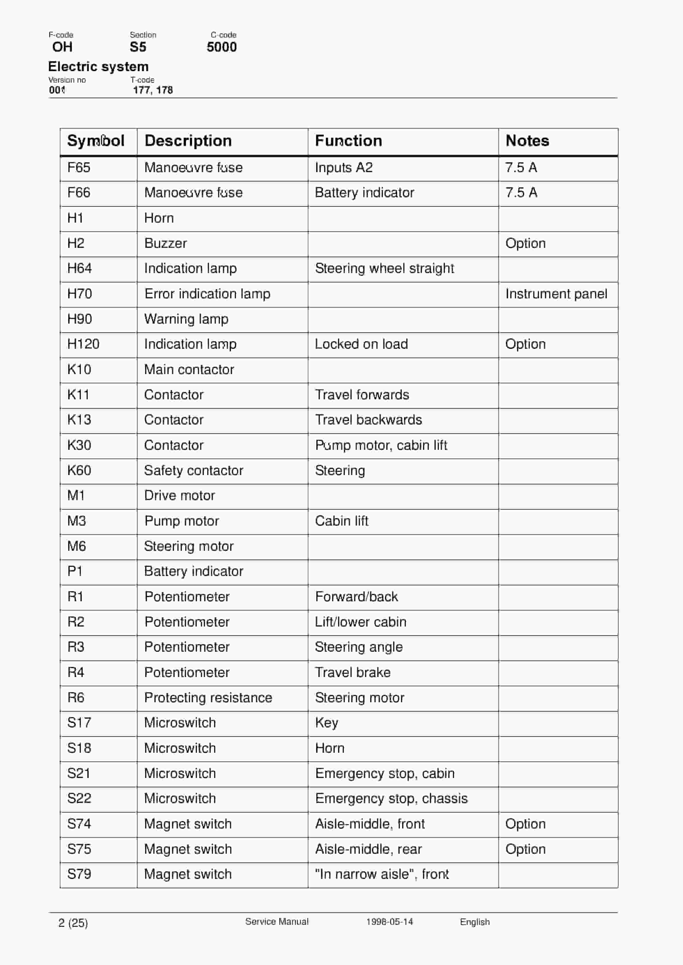
- 5.5.1.4. List of symbols
- 5.5.1.4.1. Description
- 5.5.1.4.2. Function
- 5.5.1.4.3. Electric chart (1/10)
- 5.5.1.4.4. Electric chart (2/10)
- 5.5.1.4.5. Electric chart (3/10)
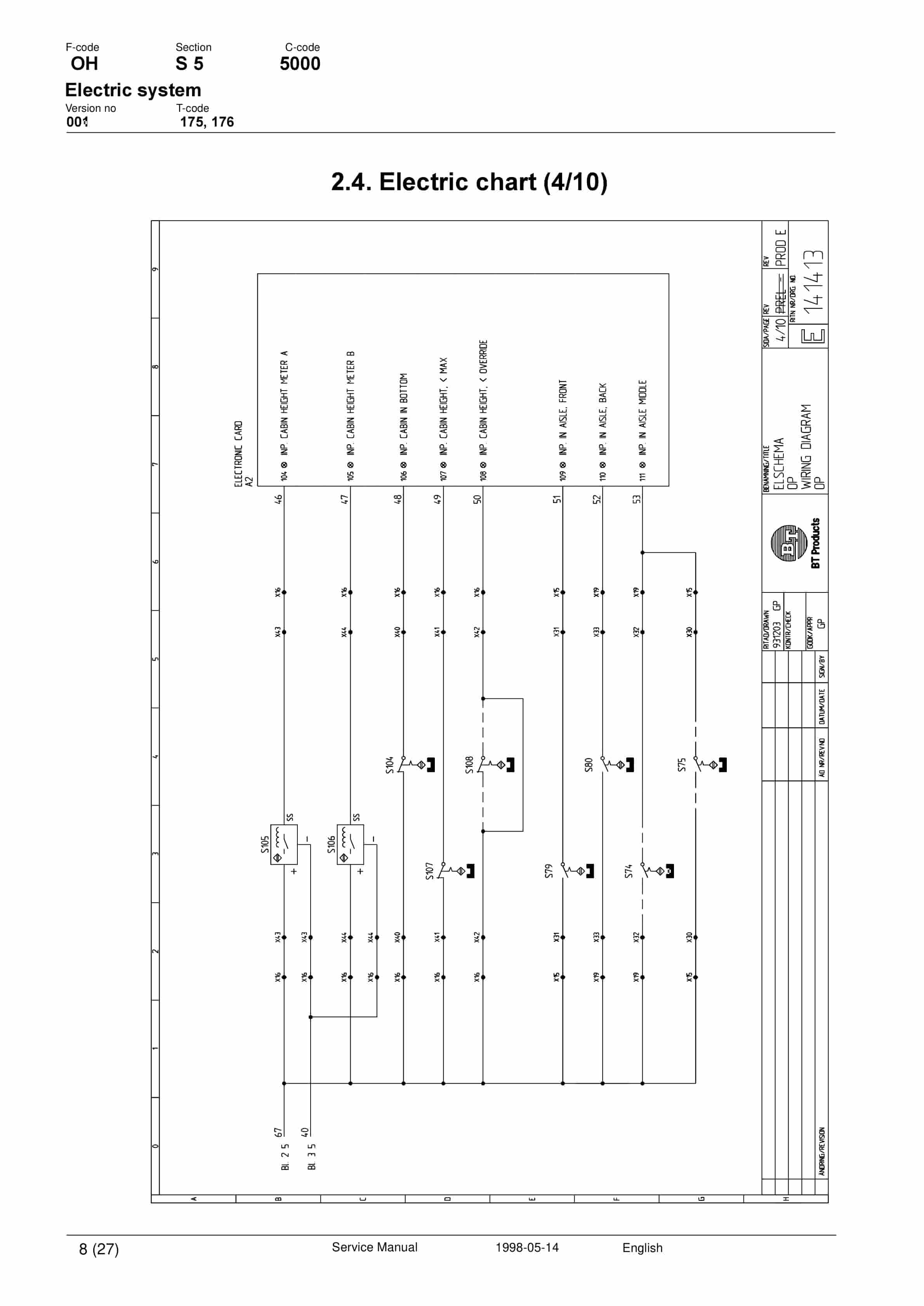
- 5.5.1.4.6. Electric chart (4/10)
- 5.5.1.4.7. Electric chart (5/10)
- 5.5.1.4.8. Electric chart (6/10)
- 5.5.1.4.9. Electric chart (7/10)
- 5.5.1.4.10. Electric chart (8/10)
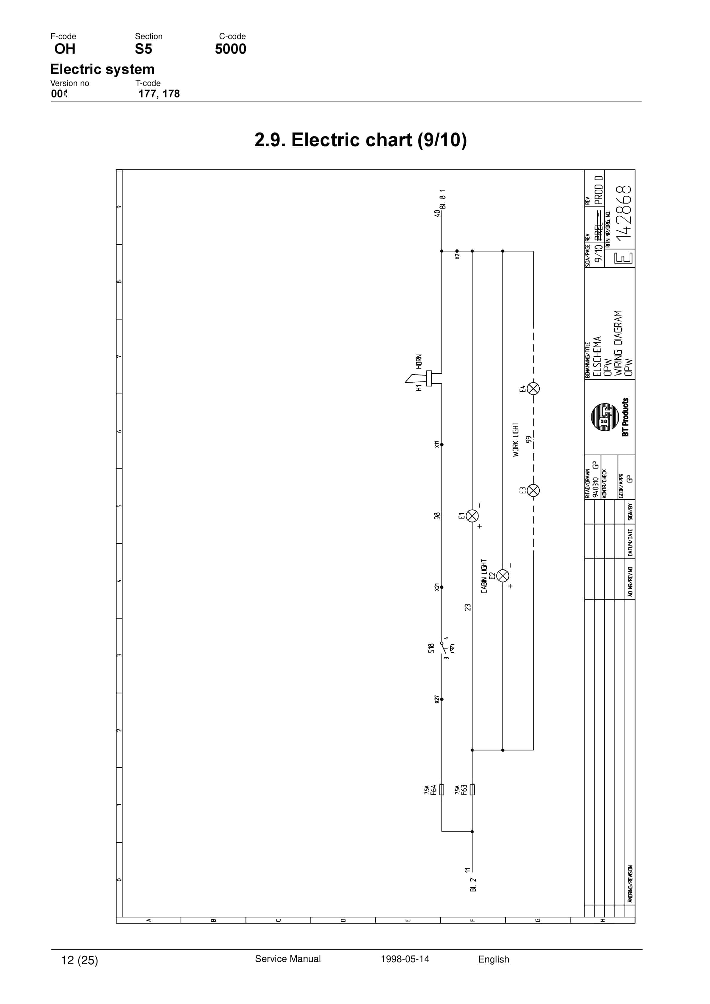
- 5.5.1.4.11. Electric chart (9/10)
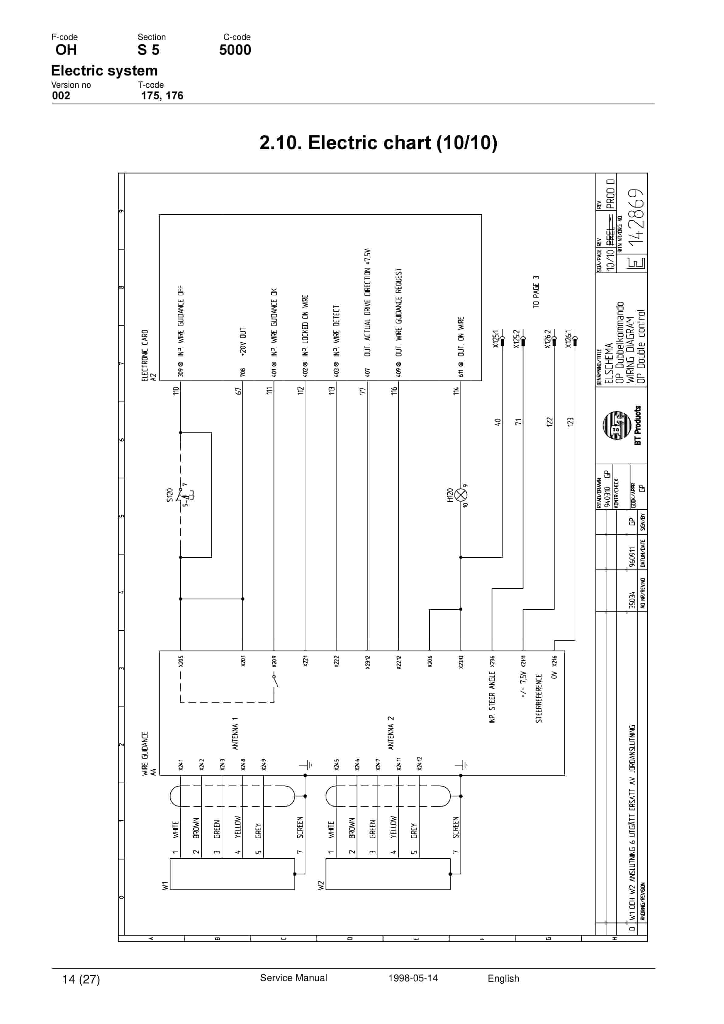
- 5.5.1.4.12. Electric chart (10/10)
- 5.5.1.5. Presentation of electric chart OP 1000/2 SE/HSE
- 5.5.1.5.1. Drive motor circuit (see electric chart 1/10)
- 5.5.1.5.2. Pump motors, cabin lift and initial lift, and also battery indicators and hour meters. (elec…
- 5.5.1.5.3. Steering servo (see electric chart 3/10)
- 5.5.1.5.4. Inputs to the electronic circuit board A2 (see electric chart 4/10)
- 5.5.1.5.5. Inputs to the electronic circuit board A2 (see electric chart 5/10)
- 5.5.1.5.6. Inputs to the electronic circuit board A2 (see electric chart 6/10)
- 5.5.1.5.7. Outputs from the electronic circuit board A2 (see electric chart 7/10)
- 5.5.1.5.8. Outputs from the electronic circuit board A2 (see electric chart 8/10)
- 5.5.1.5.9. Initial lift/lower, horn and lighting (see electric chart 9/10)
- 5.5.1.5.10. Wire guidance (see electric chart 10/10)
- 5.5.1.6. Function description electric system OP 1000/2 SE/HSE
- 5.5.1.6.1. Start-up
- 5.5.1.6.2. Check of the operators presence in the operator cabin
- 5.5.1.6.3. Deadmans handles
- 5.5.1.6.4. Driving forward-back
- 5.5.1.6.5. Travel speed
- 5.5.1.6.6. Brake
- 5.5.1.6.7. Steering
- 5.5.1.6.8. Cabin lift
- 5.5.1.6.9. Cabin lower
- 5.5.1.6.10. Slack chain guard
- 5.5.1.6.11. Initial lift
- 5.5.1.6.12. Initial lower
- 5.5.1.6.13. Other
- 5.5.1.6.14. Aisle-end brake (extra equipment)
- 5.6. gb2.pdf
- 5.6.1. Electric system
- 5.6.1.1. Valid from serial number
- 5.6.1.2. Serial No.
- 5.6.1.3. General
- 5.6.1.4. List of symbols
- 5.6.1.4.1. Description
- 5.6.1.4.2. Function
- 5.6.1.4.3. Electric chart (1/10)
- 5.6.1.4.4. Electric chart (2/10)
- 5.6.1.4.5. Electric chart (3/10)
- 5.6.1.4.6. Electric chart (4/10)
- 5.6.1.4.7. Electric chart (5/10)
- 5.6.1.4.8. Electric chart (6/10)
- 5.6.1.4.9. Electric chart (7/10)
- 5.6.1.4.10. Electric chart (8/10)
- 5.6.1.4.11. Electric chart (9/10)
- 5.6.1.4.12. Electric chart (10/10)
- 5.6.1.5. Description of electric system OP1000/2 SE/HSE with double command
- 5.6.1.5.1. Drive motor circuit (see electric chart 1/10)
- 5.6.1.5.2. Pump motors, cabin lift and initial lift, and also battery indicators and hour meters (see e…
- 5.6.1.5.3. Steering servo (see electric chart 3/10)
- 5.6.1.5.4. Inputs to the electronic circuit board A2 (see electric chart 4/10)
- 5.6.1.5.5. Inputs to the electronic circuit board A2 (see electric chart 5/10)
- 5.6.1.5.6. Inputs to the electronic circuit board A2 (see electric chart 6/10)
- 5.6.1.5.7. Outputs from the electronic circuit board A2 (see electric chart 7/10)
- 5.6.1.5.8. Outputs from the electronic circuit board A2 (see electric chart 8/10)
- 5.6.1.5.9. Initial lift/lower, sound signals and lighting (see electric chart 9/10)
- 5.6.1.5.10. Wire guidance (see electric chart 10/ 10)
- 5.6.1.6. Function description of electric system OP 1000/2 SE/HSE with double command
- 5.6.1.6.1. Start-up
- 5.6.1.6.2. Check of the operators presence in the operators cabin
- 5.6.1.6.3. Deadmans handle
- 5.6.1.6.4. Driving forward-back
- 5.6.1.6.5. Travel speed
- 5.6.1.6.6. Brake
- 5.6.1.6.7. Steering
- 5.6.1.6.8. Cabin lift
- 5.6.1.6.9. Cabin lower
- 5.6.1.6.10. Slack chain guard
- 5.6.1.6.11. Initial lift
- 5.6.1.6.12. Initial lower
- 5.6.1.6.13. Other
- 5.6.1.6.14. Aisle-end brake (extra equipment)
- 5.7. gb1.pdf
- 5.7.1. Electric system
- 5.7.1.1. Valid from serial number
- 5.7.1.2. Serial No.
- 5.7.1.3. General
- 5.7.1.4. List of symbols
- 5.7.1.4.1. Description
- 5.7.1.4.2. Function
- 5.7.1.4.3. Electric chart (1/10)
- 5.7.1.4.4. Electric chart (2/10)
- 5.7.1.4.5. Electric chart (3/10)
- 5.7.1.4.6. Electric chart (4/10)
- 5.7.1.4.7. Electric chart (5/10)
- 5.7.1.4.8. Electric chart (6/10)
- 5.7.1.4.9. Electric chart (7/10)
- 5.7.1.4.10. Electric chart (8/10)
- 5.7.1.4.11. Electric chart (9/10)
- 5.7.1.4.12. Electric chart (10/10)
- 5.7.1.5. DESCRIPTION OF ELECTRIC SYSTEM OPW 1200/2 SE/HSE
- 5.7.1.5.1. Drive motor circuit (electric chart 1/10)
- 5.7.1.5.2. Pump motor, cabin lift and also battery indicator and hour meter (electric chart 2/10)
- 5.7.1.5.3. Steering servo (electric chart 3/10)
- 5.7.1.5.4. Inputs to the electronic circuit board A2 (electric chart 4/10)
- 5.7.1.5.5. Inputs to the electronic circuit board A2 (electric chart 5/10)
- 5.7.1.5.6. Inputs to the electronic circuit board A2 (electric chart 6/10)
- 5.7.1.5.7. Outputs to the electronic circuit board A2 (electric chart 7/10)
- 5.7.1.5.8. Outputs to the electronic circuit board A2 (electric chart 8/10)
- 5.7.1.5.9. Horn and lighting (electric chart 9/10)
- 5.7.1.5.10. Wire guidance (electric chart 10/10)
- 5.7.1.6. Function description electric system OPW 1200/2 SE/HSE
- 5.7.1.6.1. Start-up
- 5.7.1.6.2. Check of the operators presence in the operators cabin
- 5.7.1.6.3. Deadmans handle
- 5.7.1.6.4. Driving forward-back
- 5.7.1.6.5. Travel speed
- 5.7.1.6.6. Brake
- 5.7.1.6.7. Steering
- 5.7.1.6.8. Cabin lift
- 5.7.1.6.9. Cabin lower
- 5.7.1.6.10. Slack chain guard
- 5.7.1.6.11. Other
- 5.7.1.6.12. Aisle-end brake (extra equipment)
- 5.8. gb1.pdf
- 5.8.1. Transistor regulator
- 5.8.1.1. Valid from serial number
- 5.8.1.2. Serial No.
- 5.8.1.3. Motor connections
- 5.8.1.3.1. Terminal number
- 5.8.1.3.2. Function
- 5.8.1.4. Contact for control voltages
- 5.8.1.4.1. Terminal number
- 5.8.1.4.2. Function
- 5.8.1.4.3. LED no.
- 5.8.1.4.4. Function
- 5.8.1.5. Safety checking
- 5.8.1.5.1. Check of the transistor regulators safety circuit
- 5.9. gb1.pdf
- 5.9.1. Electronic circuit board
- 5.9.1.1. Valid from serial number
- 5.9.1.2. Serial No.
- 5.9.1.3. General
- 5.9.1.4. Voltages on the electronic circuit board A2
- 5.9.1.4.1. Cable No.
- 5.9.1.4.2. Description
- 5.9.1.4.3. Functions on the display on the electronic circuit board A2.
- 5.9.1.4.4. Programmable parameters
- 5.9.1.4.5. Programming state
- 5.9.1.4.6. Selection of parameter
- 5.9.1.4.7. Selection of value
- 5.9.1.4.8. Programming of new value
- 5.9.1.4.9. Exiting the programming
- 5.9.1.4.10. A2 Electronic circuit board
- 5.9.1.5. Adjusting instruction electric system OP/OPW
- 5.9.1.5.1. Adjustment of mid-position steered wheel (drive wheel)
- 5.9.1.5.2. Adjustment (offset) cabin lift
- 5.9.1.5.3. Adjustment (offset) cabin lower
- 5.9.1.5.4. Adjustment of the drive motors pulse transducer
- 5.9.1.5.5. Adjustment (offset) steering motor, the A3 box
- 5.9.1.5.6. Adjustment of height measurement transducer
- 5.9.1.5.7. A3 Steering servo
- 5.9.1.5.8. A3 Steering servo
- 5.9.1.5.9. A5 Logic box valve steering initial lift/ lower
- 5.9.1.6. Emergency drive function
- 5.9.1.6.1. Immediately after the switching on with the ignition key the joystick is moved to its front po…
- 5.9.1.6.2. Thereafter, within 2 seconds, the joy-stick is moved to its back position (travel). Hold there…
- 5.9.1.6.3. Thereafter, within 2 seconds, the joy-stick is moved to its most right position (brake). Hold …
- 5.9.1.6.4. Move the joystick back to its neutral position and wait until the lamp has blinked three times…
- 5.9.1.6.5. You can now drive the truck at low speed. Drive carefully, as the truck has several of its sup…
- 5.10. gb1.pdf
- 5.10.1. Hydraulic system
- 5.10.1.1. Valid from serial number
- 5.10.1.2. Serial No.
- 5.10.1.3. General
- 5.10.1.4. Function description
- 5.10.1.4.1. Cabin lift, joystick upwards
- 5.10.1.4.2. Cabin lift, joystick downwards
Related products
-
BT C4E250V, C4E300V, C4E300VL, C4E350V Repair Manual 036-0428-01
$30.00 Add to cart -
BT CBD-G 2.5, 3.0, 3.5 Service Manual 036-0405-01
$30.00 Add to cart -
BT CSX10, CSX20, CSX30, CSX40, WSX22, WSX30, WSX40, WRX30 Electric Walkie High Lifter Truck Service Manual 304959-000
$30.00 Add to cart -
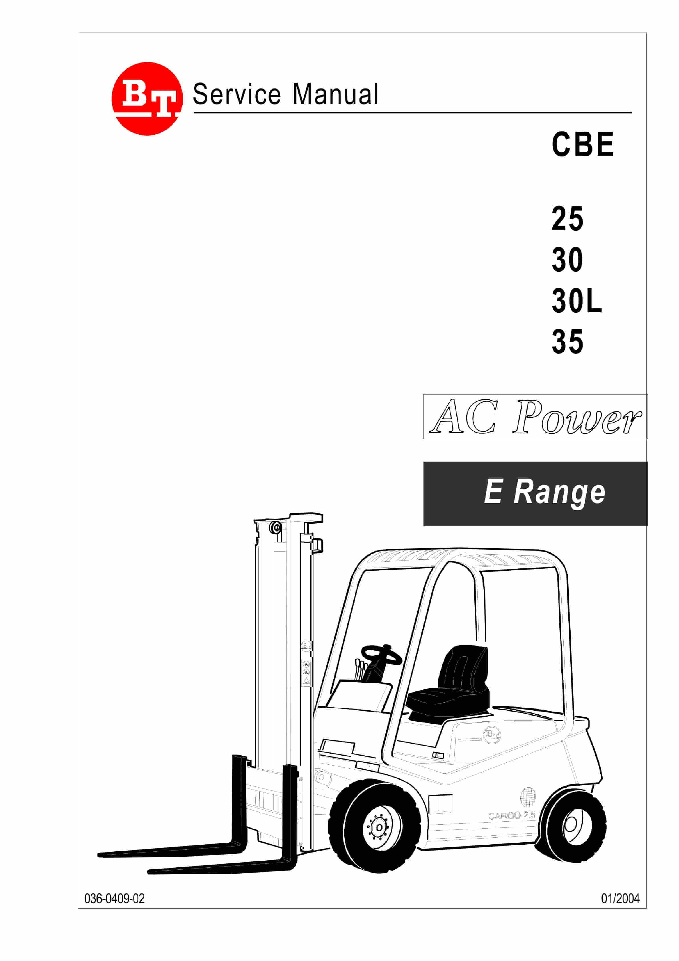
BT CBE 25, CBE 30, CBE 30L, CBE 35 Service Manual 036-0409-02
$30.00 Add to cart -
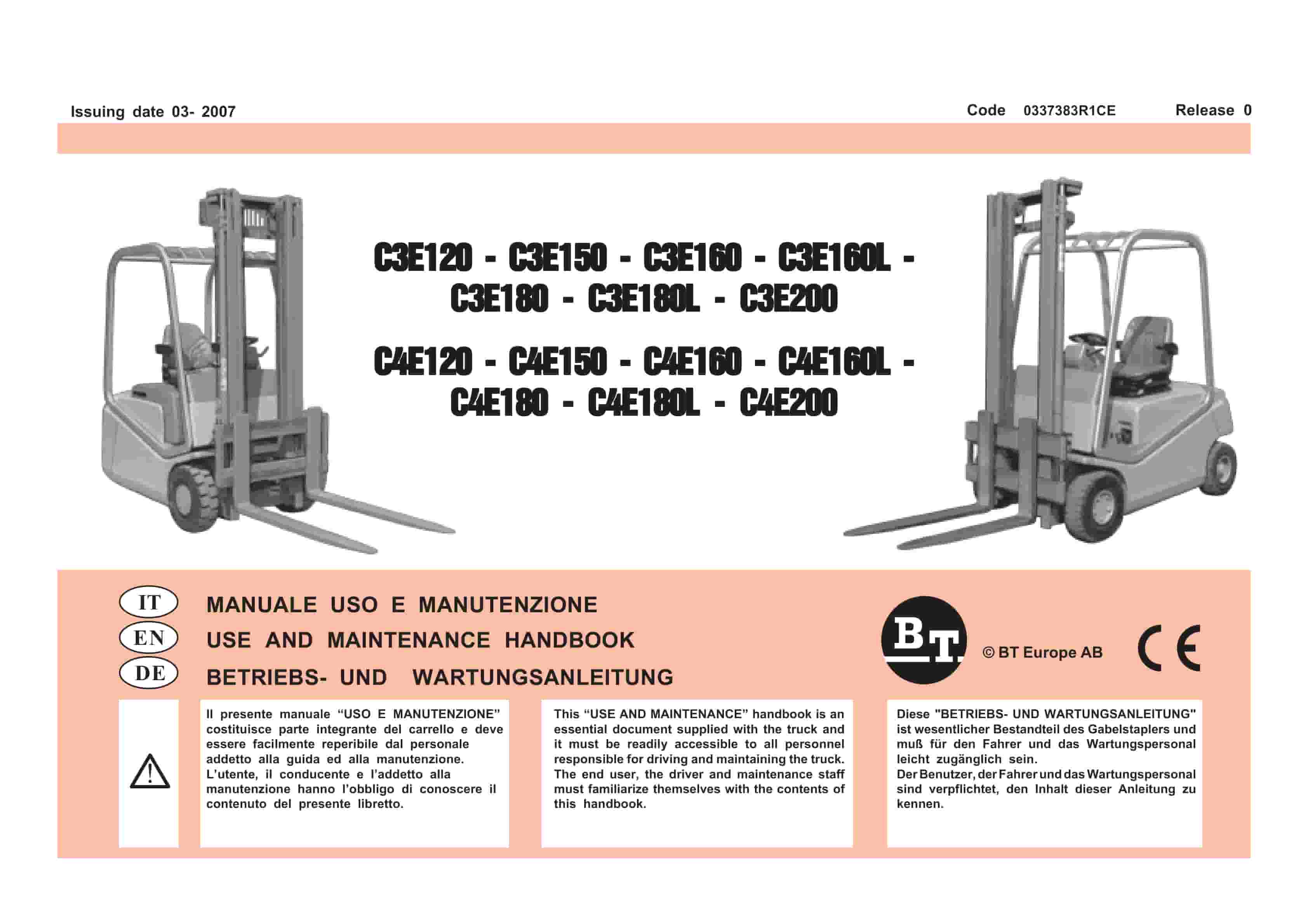
BT C3E120 to C4E200 Use And Maintenance Handbook 0337383R1CE
$30.00 Add to cart


