


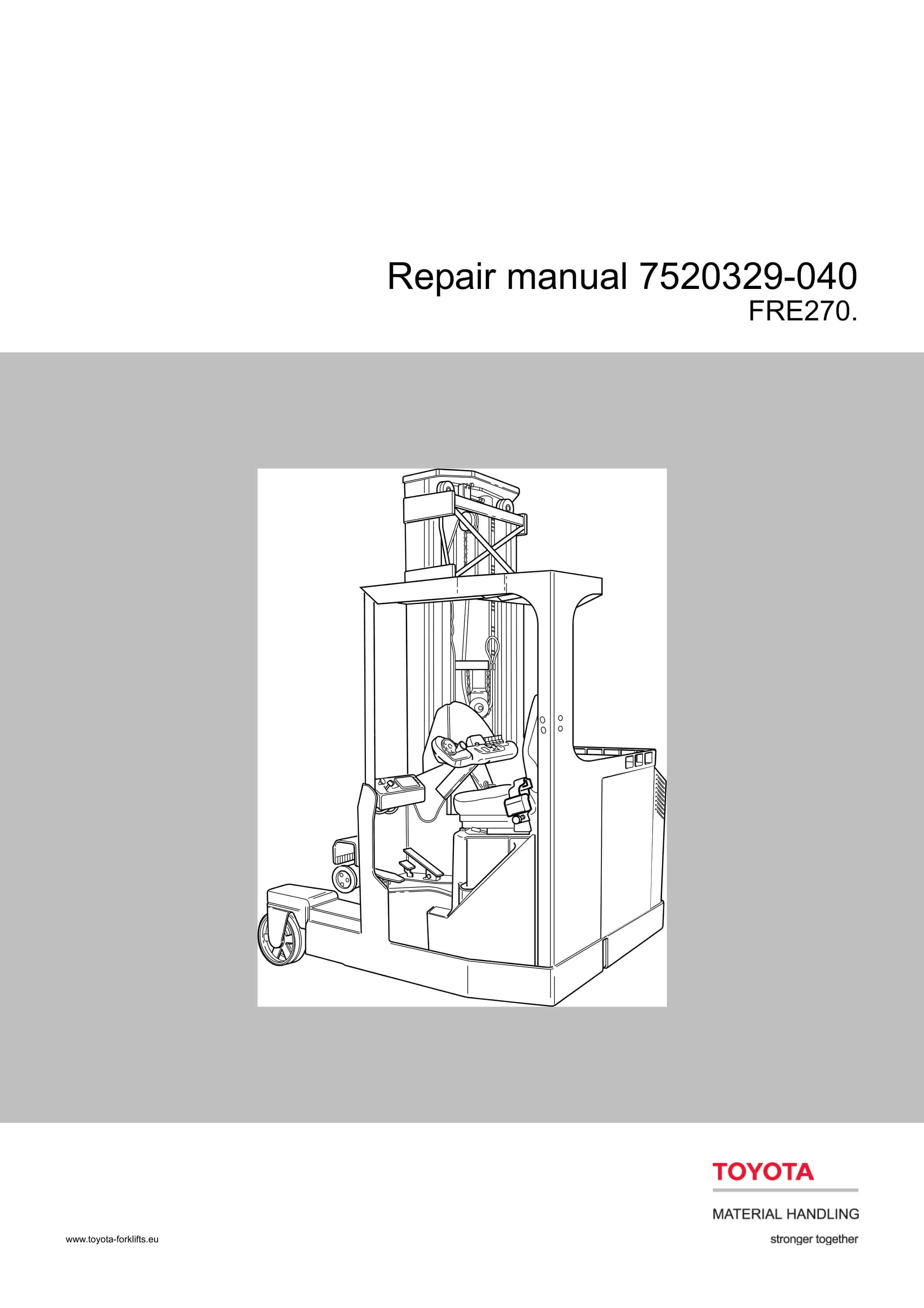
BT RRX35, RRX45, RDX30, RSX40, RSX50 Electric Stand-Up Rider Truck Service Manual 306756-000
$30.00
- Type Of Manual: Service Manual
- Manual ID: 306756-000
- : Service Manual PDF
- Number of Pages: 614
- Size: 23.9MB
- Format: PDF
Category: BT Service Manual PDF
-
Model List:
- RRX35, RRX45, RDX30, RSX40, RSX50 Electric Stand-Up Rider Truck
- 1. Standard Codes
- 2. Warning Symbols
- 2.1. Warning Levels
- 3. Prohibitory Symbols
- 3.1. Ordinance Symbols
- 3.2. General Safety
- 4. Battery Safety
- 5. Static Safety
- 6. Welding Safety
- 7. Introduction, Service Manual
- 8. Contents, Section M
- 8.1. Machine Information
- 9. General Product Information
- 9.1. Presentation of the Rider Trucks.
- 9.2. Main Components
- 10. Inch (SAE) and Metric Fasteners
- 10.1. Introduction
- 10.2. Nomenclature, Threads
- 10.3. Strength Identification
- 10.4. Conversion of Metric and English Units
- 11. Technical Service Data
- 12. Ordering Spare Parts
- 13. Contents, Section P
- 13.1. Planned Maintenance
- 14. Introduction, Maintenance
- 14.1. Jacking Truck Off The Floor
- 14.2. Lubricants
- 15. Service Schedule
- 15.1. Planned Maintenance Schedule
- 15.2. Planned Maintenance Procedures
- 16. Lubrication Chart
- 17. Oil and Grease Specifications
- 17.1. Approved Oils and Grease
- 17.2. Grease Location Points
- 17.3. Mast Adjustment Points
- 18. Contents, Section S
- 18.1. Service Instructions
- 19. Troubleshooting Guidelines
- 19.1. General
- 19.2. Electrical
- 19.3. Hydraulic
- 19.4. Definitions
- 20. Chassis
- 20.1. General
- 20.2. Dash
- 20.3. Motor Compartment Door
- 20.4. Left-Hand Side Panel
- 20.5. Operator Compartment Panel
- 20.6. Main Card Access Panel
- 21. Battery Compartment
- 21.1. Battery Retainer Plates
- 21.2. Battery Rollers
- 22. Driver Controls
- 23. Brake Pedal, RSX40/RRX35
- 23.1. Pedal Removal
- 23.2. Pedal Bearing Replacement
- 23.3. Pedal Adjustment
- 24. Brake Pedal, RSX50/RRX45/ RDX30
- 24.1. Pedal Removal
- 24.2. Pedal Bearing Replacement
- 24.3. Pedal Adjustment
- 25. Overhead Guard
- 25.1. Decal with Protective Sheet
- 25.2. Decal without Protective Sheet
- 26. Steering Motor
- 26.1. Removal
- 26.2. Installation
- 26.3. Steering Motor Gear Replacement
- 27. Fan Motor
- 27.1. Upper Electrical Compartment Fan
- 27.2. Operator Fan
- 28. Motor Maintenance Schedule/Troubleshooting
- 28.1. General Information
- 28.2. Operating Conditions
- 28.3. Troubleshooting
- 29. Motor Repair
- 29.1. Disassembly
- 29.2. Motor Inspection
- 30. Pump Motor
- 30.1. Mounting Points
- 30.2. Repair
- 31. Drive Motor
- 31.1. Mounting Points
- 31.2. Repair
- 32. Transmission
- 32.1. Mounting Points
- 32.2. Repair
- 32.3. Disassemble
- 32.4. Assembly
- 32.5. Axle Sealing Ring
- 32.6. Leakage
- 32.7. Wheel Bolt
- 33. Electromagnetic Brake
- 33.1. Removal
- 33.2. Installation
- 33.3. Adjustments
- 33.4. Coil Check On Brake
- 33.5. Electromagnetic Brake, Armature and Magnetic Coil
- 33.6. Brake Friction Plate
- 34. Drive Wheel
- 34.1. Removal
- 34.2. Installation
- 34.3. Tire Pressing Procedure
- 35. Non-Braking Caster Wheel, RRX35/ RSX40
- 35.1. Caster Pivot
- 35.2. Thrust Bearing
- 35.3. Caster Springs
- 35.4. Caster Stops
- 36. Non-Braking Caster Assembly, RRX35/RSX40
- 36.1. Removal
- 36.2. Installation
- 37. Braking Caster Wheel, RRX45/RDX30/ RSX50
- 37.1. Removal
- 38. Braking Caster Assembly, RRX45/ RDX30/RSX50
- 38.1. Removal
- 38.2. Installation
- 39. Load Wheels, Sizes 4 X 3, 5 X 4, and 5 X 3
- 39.1. Removal
- 39.2. Installation
- 40. Load Wheels, Size 10.5 X 3.5
- 40.1. Removal
- 40.2. Installation
- 41. Steering Arm / Wheel / Lever
- 41.1. Control Pod
- 41.2. Steering Wheel
- 41.3. Steering Tach
- 42. Steering Bearing
- 42.1. Removal
- 42.2. Installation
- 43. Electrical Functions
- 43.1. General
- 43.2. Start Up
- 43.3. Steering Components
- 43.4. Brake Release
- 43.5. Direction Selection
- 43.6. Travel Request, Forks First
- 43.7. Travel Request, Forks Trailing
- 43.8. Plug Braking
- 43.9. Volt Power Supply
- 43.10. Volt Power Supplies
- 43.11. Limit Switches
- 43.12. Height Indicator
- 43.13. Drive Motor Brush Wear Indicator Switches
- 43.14. Pump Motor Brush Indicator Switch
- 43.15. Safety Check
- 43.16. Shunt Power Cable
- 44. Electrical Symbols
- 45. Electrical Schematics (Serial numbers 27163000-28105000)
- 45.1. Circuit Diagram 1(11)
- 45.2. Circuit Diagram 2(11)
- 45.3. Circuit Diagram 3(11)
- 45.4. Circuit Diagram 4(11)
- 45.5. Circuit Diagram 5(11)
- 45.6. Circuit Diagram 6(11)
- 45.7. Circuit Diagram 7(11)
- 45.8. Circuit Diagram 8(11)
- 45.9. Circuit Diagram 9(11)
- 45.10. Circuit Diagram 10(11)
- 45.11. Circuit Diagram 11(11)
- 46. Electrical Schematics (Serial numbers 28105001-28126000)
- 46.1. Circuit Diagram 1(12)
- 46.2. Circuit Diagram 2(12)
- 46.3. Circuit Diagram 3(12)
- 46.4. Circuit Diagram 4(12)
- 46.5. Circuit Diagram 5(12)
- 46.6. Circuit Diagram 6(12)
- 46.7. Circuit Diagram 7(12)
- 46.8. Circuit Diagram 8(12)
- 46.9. Circuit Diagram 9(12)
- 46.10. Circuit Diagram 10(12)
- 46.11. Circuit Diagram 11(12)
- 46.12. Circuit Diagram 12(12)
- 47. Electrical Schematics (Serial numbers 28126001-31285000)
- 47.1. Circuit Diagram 1(12)
- 47.2. Circuit Diagram 2(12)
- 47.3. Circuit Diagram 3(12)
- 47.4. Circuit Diagram 4(12)
- 47.5. Circuit Diagram 5(12)
- 47.6. Circuit Diagram 6(12)
- 47.7. Circuit Diagram 7(12)
- 47.8. Circuit Diagram 8(12)
- 47.9. Circuit Diagram 9(12)
- 47.10. Circuit Diagram 10(12)
- 47.11. Circuit Diagram 11(12)
- 47.12. Circuit Diagram 12(12)
- 48. Electrical Schematics (Serial numbers 31285001-UP)
- 48.1. Circuit Diagram 1(12)
- 48.2. Circuit Diagram 2(12)
- 48.3. Circuit Diagram 3(12)
- 48.4. Circuit Diagram 4(12)
- 48.5. Circuit Diagram 5(12)
- 48.6. Circuit Diagram 6(12)
- 48.7. Circuit Diagram 7(12)
- 48.8. Circuit Diagram 8(12)
- 48.9. Circuit Diagram 9(12)
- 48.10. Circuit Diagram 10(12)
- 48.11. Circuit Diagram 11(12)
- 48.12. Circuit Diagram 12(12)
- 49. Battery
- 49.1. Removal
- 49.2. Installation
- 49.3. Battery Maintenance
- 49.4. Storage
- 49.5. Battery History Record
- 50. Light Assemblies
- 50.1. Overhead Guard Lights (Option)
- 50.2. Warning Lights (Option)
- 50.3. Working Lights (Option)
- 50.4. Travel Alarm (Option)
- 50.5. Operator Fan (Option)
- 50.6. Removal
- 50.7. Installation
- 51. Start/Stop Switches
- 51.1. General
- 51.2. Key Switch (S17)
- 51.3. Emergency Disconnect Switch (S21)
- 52. Battery Connector
- 52.1. Location
- 52.2. Inspection
- 52.3. Installation
- 53. Mast Switch (S31)
- 53.1. General
- 54. Control Cable and Harness
- 54.1. Fuses
- 54.2. Wiring
- 55. Contactors
- 55.1. General
- 55.2. Direction Contactors
- 55.3. Lift Bypass Contactor (RRX45/RSX50/RDX30)
- 55.4. Main Contactor
- 56. Transistor Panel (Drive)
- 56.1. Motor Connections
- 57. Transistor Panel (Lift)
- 57.1. Circuit Check, Drive Only
- 58. Micro Switches
- 58.1. General
- 58.2. Lift Limit Override Switch (S33) Optional
- 58.3. Optional Light and Fan Switches (S96, S97 and S99)
- 59. Main Electronic Card
- 59.1. Connectivity to Truck
- 59.2. Transistor Controller Replacement
- 59.3. Removal
- 59.4. Installation
- 59.5. Display
- 59.6. Time
- 59.7. Effect on Truck
- 59.8. Running time
- 59.9. RV2 Adjustment Procedure
- 59.10. Adjustment Procedures for Setting Brake Switch and Brake Transducer
- 59.11. Battery Discharge Indicator Parameter Adjustment
- 59.12. A5 Jumper Harness Kit Installation (Serial numbers 28126000 – below)
- 59.13. WarningCaution Codes
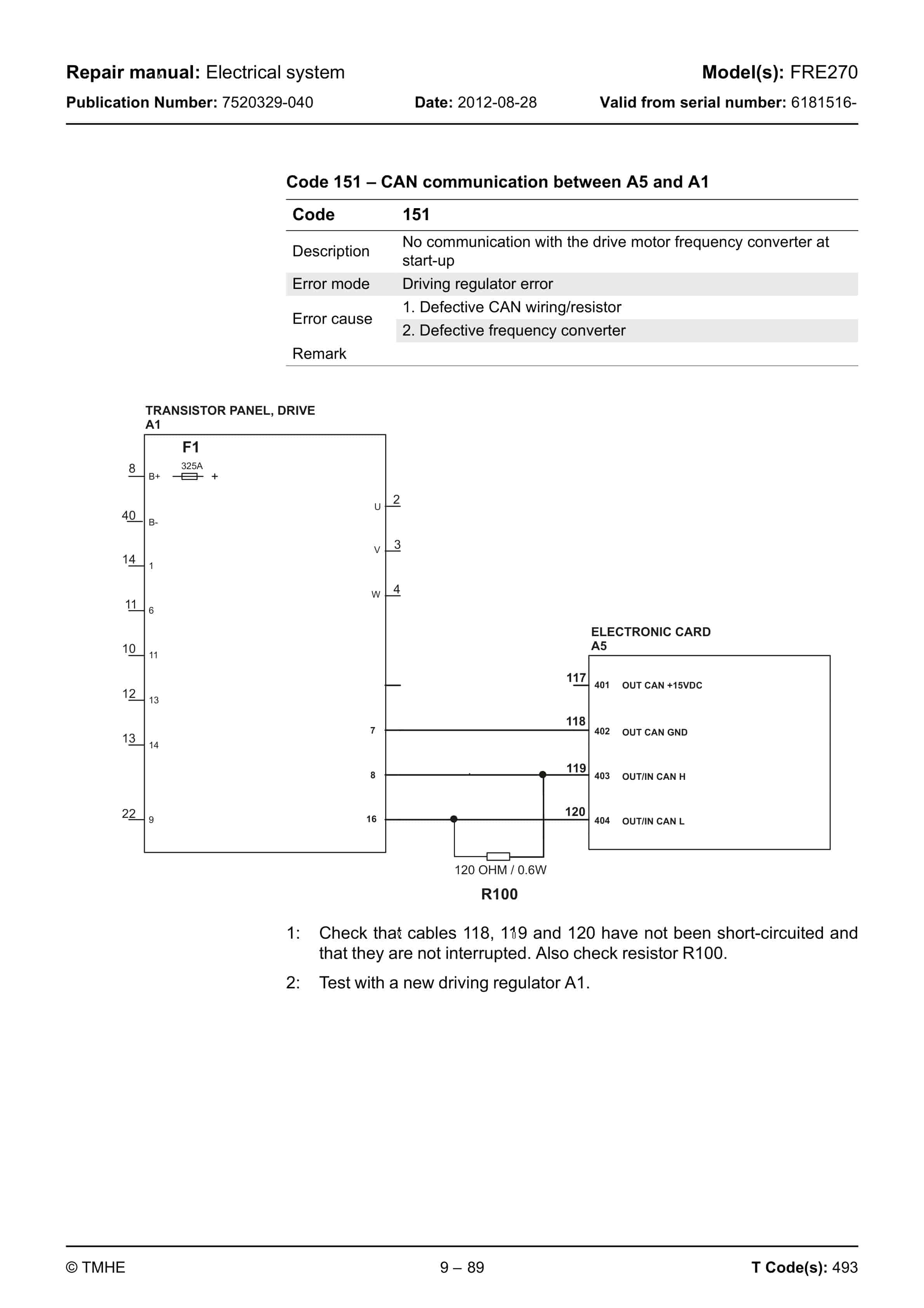
- 59.14. Error Codes
- 59.15. Programming Parameter
- 60. Switches and Sensors
- 60.1. General
- 60.2. Platform (Right Foot) Switch (S108)
- 60.3. Staging Switch (S45)
- 60.4. Wheel Direction Sensor
- 60.5. Steer Proximity Sensors A and B (S66 and S67)
- 60.6. Drive Motor Speed(S64)/Direction Sensors (S125)
- 61. Hydraulic System
- 61.1. Operation
- 61.2. RRX35 Hydraulic Schematic
- 61.3. RRX45 Hydraulic Schematic
- 61.4. RDX30 Hydraulic Schematic
- 61.5. RSX40 Hydraulic Schematic
- 61.6. RSX50 Hydraulic Schematic
- 62. Hydraulic Fluid
- 62.1. Hydraulic Fluid Selection
- 62.2. Changing Hydraulic System Fluid
- 62.3. System Draining
- 62.4. Refilling System
- 62.5. Bleeding Hydraulic System
- 63. Hydraulic Tank
- 63.1. Removal
- 63.2. Installation
- 64. Hydraulic Filter Assembly
- 64.1. Hydraulic Filter
- 64.2. Hydraulic Filter Adapter
- 65. Hydraulic Pump
- 65.1. Removal
- 65.2. Repair
- 66. Control Valve
- 66.1. Removal
- 66.2. Installation
- 67. Control Valve Assembly
- 67.1. Repair
- 68. Staging Cylinder, Three Stage Mast
- 68.1. Bearing Removal
- 68.2. Disassembly
- 68.3. Assembly
- 68.4. Installation
- 69. Freelift Cylinder, Three Stage Mast
- 69.1. Removal
- 69.2. Disassembly
- 69.3. Assembly
- 69.4. Installation
- 70. Reach Cylinder Assembly
- 70.1. Removal
- 70.2. Disassembly
- 70.3. Inspection
- 70.4. Assembly
- 70.5. Installation
- 71. Tilt Cylinder Assembly, RRX35/RSX40/ RSX50
- 71.1. Removal
- 71.2. Disassembly
- 71.3. Inspection
- 71.4. Assembly
- 71.5. Installation
- 72. Tilt Cylinder Assembly, RRX45/RDX30
- 72.1. Removal
- 72.2. Disassembly
- 72.3. Inspection
- 72.4. Assembly
- 72.5. Installation
- 73. Mast, 3 Stage
- 73.1. Shimming Carriage with Mast on Truck
- 73.2. Three Stage Mast
- 73.3. Lift Chain
- 74. Lifting Gear (Crosshead)
- 74.1. Lifting Gear Repair
- 75. Sideshifter, RRX35/45/RDX30
- 75.1. Mounting Instructions
- 75.2. Operation and Maintenance
- 76. Sideshifter, RRX35/45/RSX40/50/RDX30
- 76.1. Mounting Instructions
- 76.2. Operation
- 76.3. Maintenance
- 76.4. Troubleshooting
- 77. Single Reach, RRX35
- 77.1. Maintenance
- 77.2. Reach Repair
- 77.3. Carriage Bumpers
- 77.4. Fork Carriage Pivot Pins
- 77.5. Carriage Roller Bearings
- 78. Single Reach, RRX45
- 78.1. Maintenance
- 78.2. Reach Repair
- 78.3. Fork Carriage Pivot Pins
- 78.4. Carriage Roller Bearings
- 79. Double Reach Mechanism, RDX30
- 79.1. Bearing
- 79.2. Bearing, 3 stage
- 79.3. Ring, Nilos
- 79.4. Cap, bearing
- 79.5. Bearing, thrust
- 79.6. Set, bearing
- 79.7. Bearing
- 79.8. Bearing
- 79.9. Tilt cylinder assembly
- 79.10. Pin, roll
- 79.11. Screw, socket head
- 79.12. Frame, forward
- 79.13. Nut, lock
- 79.14. Screw, socket head
- 79.15. Bearing
- 79.16. Lockwasher
- 79.17. Reach cylinder assembly
- 79.18. Screw, cap
- 79.19. Nut, slotted
- 79.20. Fitting, grease
- 79.21. Manifold
- 79.22. Frame, rear
- 79.23. Control valve
- 79.24. Ring, Nilos
- 79.25. Washer, shim
- 79.26. Cone, bearing
- 79.27. Screw, cap
- 79.28. Race, bearing
- 79.29. Bar, wear
- 79.30. Nut, flanged
- 79.31. Ring, retainer
- 79.32. Theory of Operation
- 79.33. Maintenance
- 79.34. Troubleshooting
- 79.35. Repair
- 79.36. Rebuild
- 79.37. Removal
- 79.38. Inspection
- 79.39. Installation
- 80. Load Indicator
- 81. Load Indicator
- 81.1. Pulse Sensor
- 82. Height Indicator and Preset Selector
- 82.1. General
- 82.2. Operation
- 82.3. Preset Height
- 82.4. Display
- 82.5. Display Symbols Description
- 82.6. Programming
- 83. Load Backrest
- 83.1. Removal
- 83.2. Installation
Rate this product
You may also like
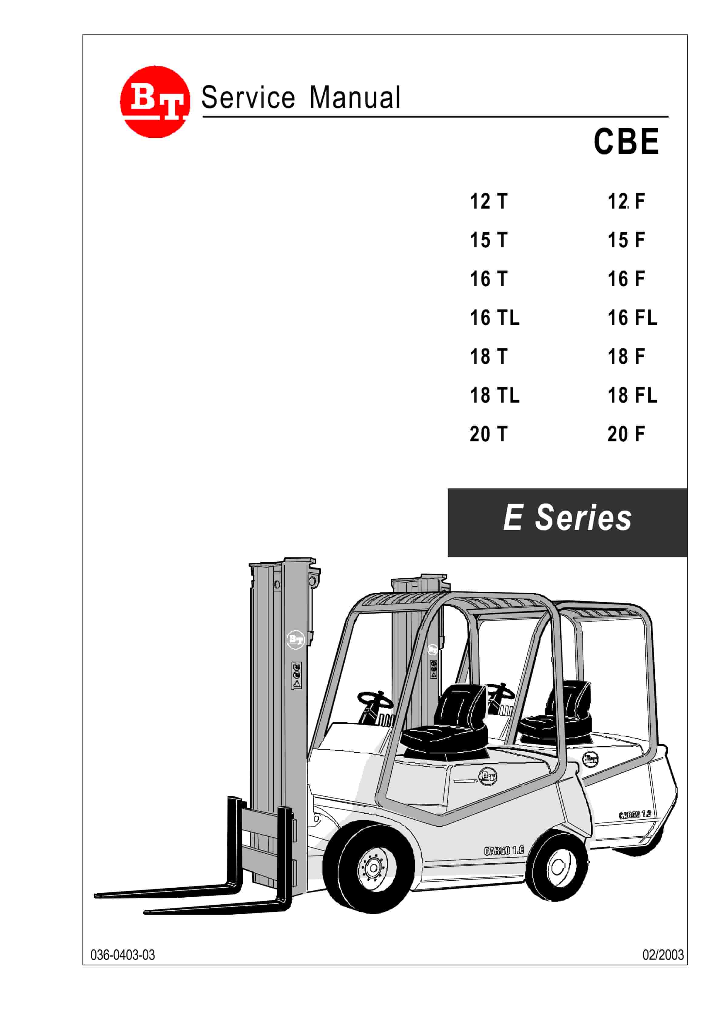
BT Service Manual PDF
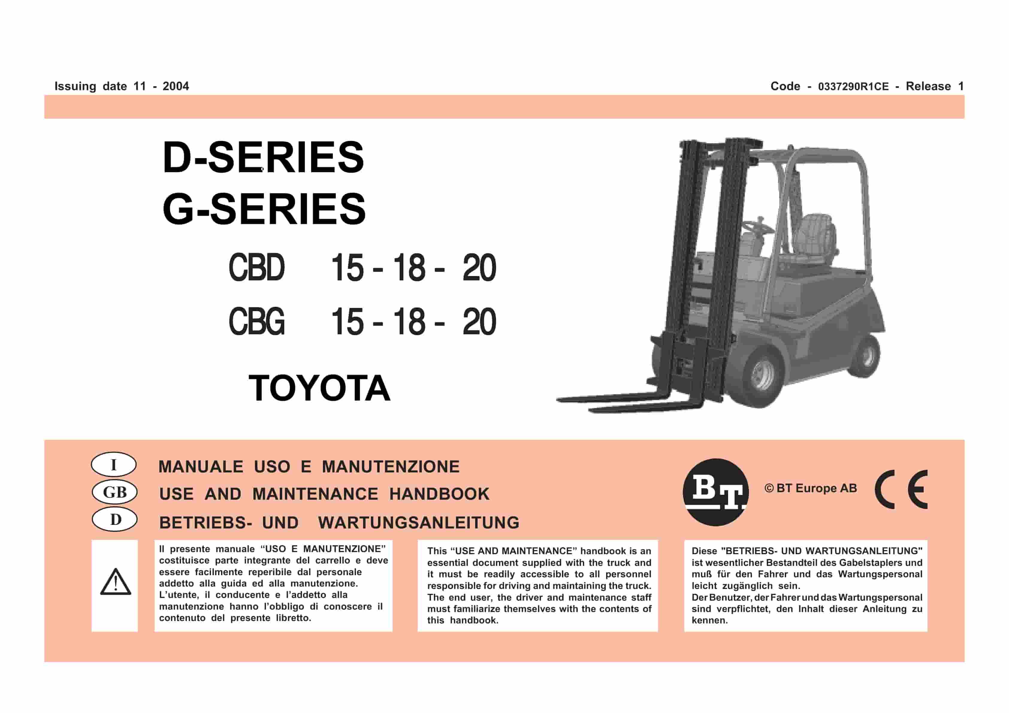
BT D-G-Series CBD15, CBD18, CBD20, CBG15, CBG18, CBG20 Use And Maintenance Handbook 0337290R1CE
$30.00
BT Service Manual PDF
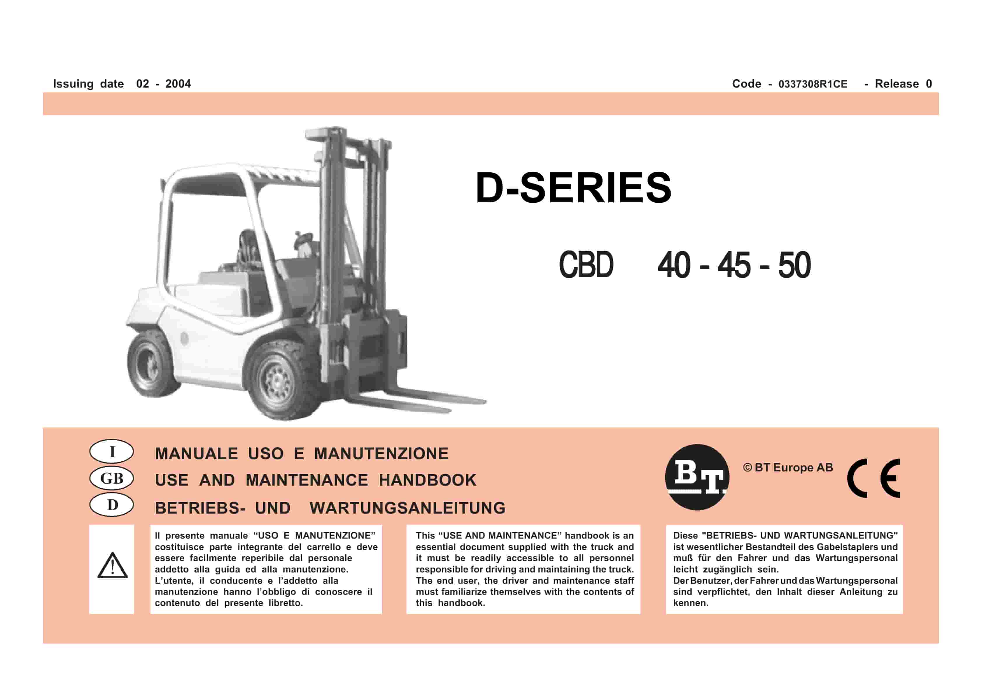
BT D-Series CBD40, CBD45, CBD50 Use And Maintenance Handbook 0337308R1CE
$30.00
BT Service Manual PDF
$30.00