

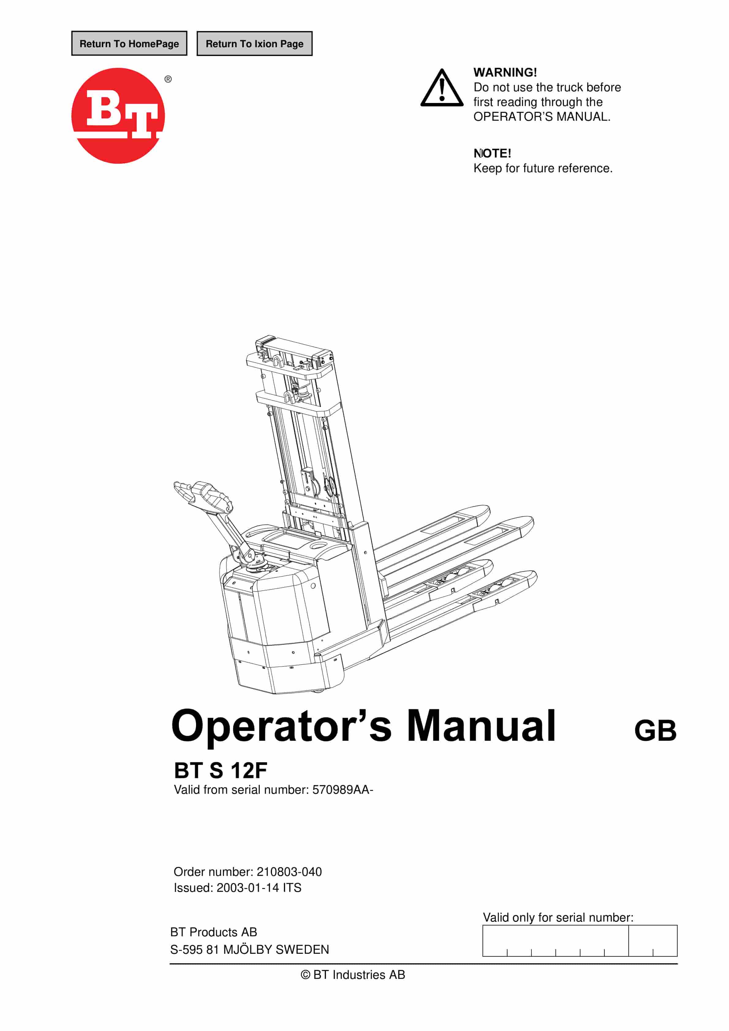
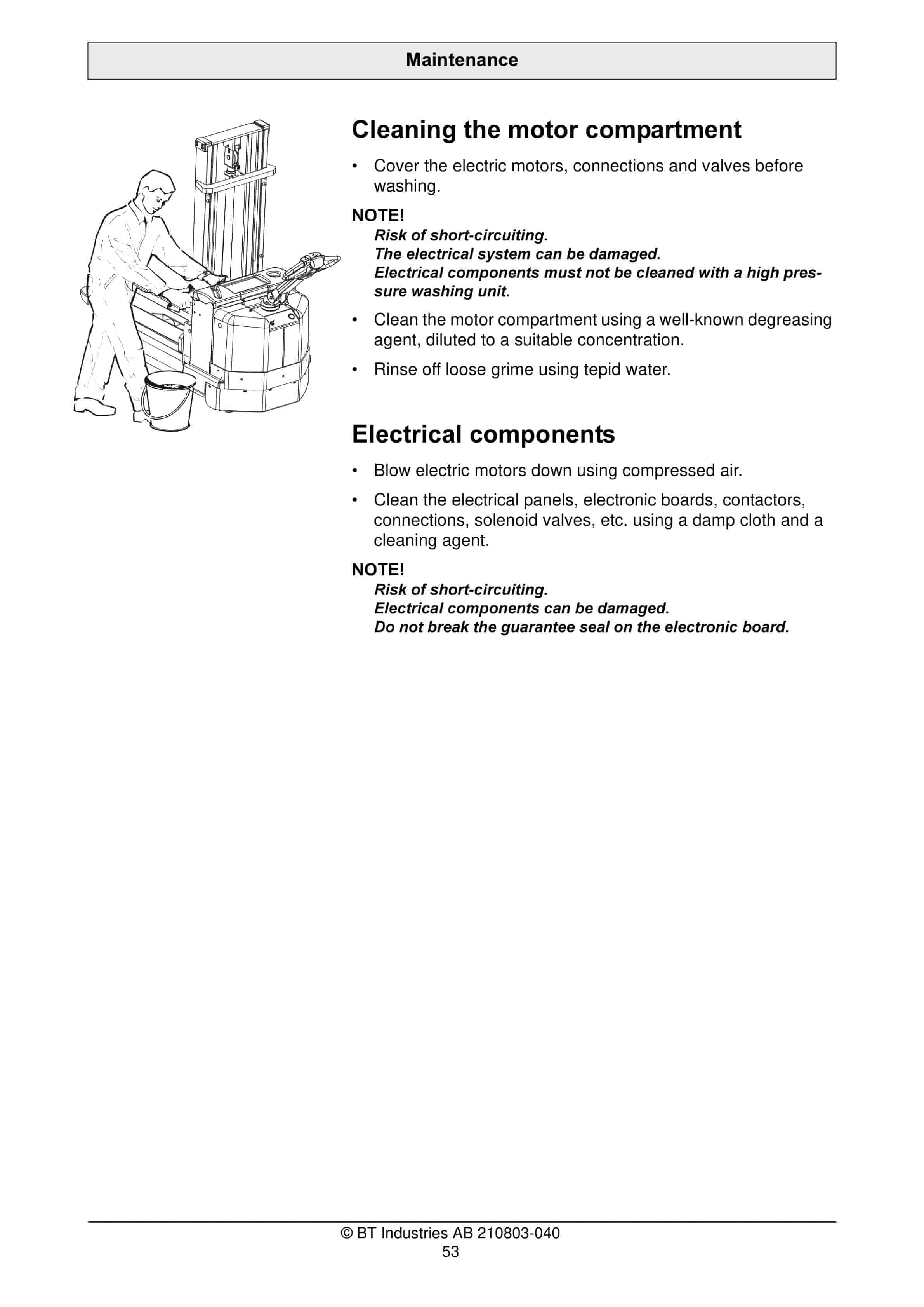
BT S 12F Operator Manual 210803-040
$30.00
- Type Of Manual: Operator Manual
- Manual ID: 210803-040
- : Operator Manual PDF
- Number of Pages: 66
- Size: 3.8MB
- Format: PDF
Product details
-
Model List:
- S 12F
- 1. Return To HomePage
- 2. BT S 12F
- 2.1. Valid from serial number 570989AA-
- 2.2. Order number 210803-040
- 2.2.1. Issued 2003-01-14 ITS
- 2.2.1.1. It is important that you read this Operators Manual for your own safety
- 3. Safety regulations
- 3.1. Warning symbols
- 3.1.1. Warning levels
- 3.1.1.1. DANGER
- 3.1.1.2. WARNING
- 3.1.1.3. CAUTION
- 3.1.2. Prohibitory symbols
- 3.1.2.1. NO SMOKING
- 3.1.2.2. NAKED FLAMES PROHIBITED
- 3.1.2.3. GENERAL PROHIBITION
- 3.1.3. Ordinance symbols
- 3.1.3.1. SAFETY SHOES
- 3.1.3.2. PROTECTIVE GLASSES
- 3.2. General safety regulations
- 3.2.1. Operating the truck
- 3.2.2. Operators responsibility
- 3.2.3. Working area
- 3.2.4. Driving and conduct while driving
- 3.2.5. Handling loads
- 3.2.6. Parking the truck
- 3.2.7. Handling the battery
- 3.2.8. Maintenance and repair
- 4. Warning and information plates and symbols
- 4.1. Hydraulic lever Lifting/lowering of the forks
- 4.2. Hydraulic lever Lifting/lowering of the support arms
- 4.3. Travel direction
- 4.4. Signal/Horn
- 4.5. Capacity plate
- 4.6. Identification plate, A CE, B ASME, depending on market
- 4.7. Hydraulic control Lower
- 4.8. Serial number
- 4.9. Hydraulic oil filling
- 4.10. Do not walk under an elevated load B) Do not stand on the forks
- 4.11. Lifting points
- 4.12. Modification plate
- 4.13. Maximum height for rated capacity
- 5. Presentation of the truck
- 5.1. Intended application of the truck
- 5.2. Forbidden application of the truck
- 5.3. Truck data
- 5.3.1. Truck type
- 5.4. Truck dimensions
- 5.4.1. Measure
- 5.4.2. Value (mm)
- 5.5. Identification plate
- 5.6. Modification plate
- 6. Main components
- 6.1. Tiller arm The truck is manoeuvred by the driver while walking. 204 degree steering area. The…
- 6.2. Identification plate With model designation, serial number, year of manufacture, weight witho…
- 6.3. Covers Removable which provides good accessibility when servicing.
- 6.4. Emergency switch off
- 6.5. Hydraulic control For controlling lifting and lowering functions.
- 6.6. Hydraulic unit Pump motor, pump and oil tank are integrated in a compact unit.
- 6.7. Hydraulic valves The valves are located to provide easy access.
- 6.8. Drive unit with brake Suspended drive unit with spring-loaded mechanical brake, travel motor,…
- 6.9. Serial number The serial number plate fitted to the chassis.
- 6.10. Electric panel Removable, which provides good access when servicing. 24 volt electrical supp…
- 6.11. Support castor wheels Two support castor wheels to ensure stability.
- 6.12. Battery 24V with different Ah values. The battery is automatically locked in the battery com…
- 6.13. Emergency disconnector and battery connector The battery is charged via the permanently fitt…
- 6.14. Mast Fitted with a finger guard to cover the drivers normal reach.
- 7. Controls and instruments
- 7.1. Control for lifting and lowering the forks
- 7.2. Control for lifting and lowering the support arms
- 7.3. Switch for safety reversing
- 7.4. Travel direction selector and speed control
- 7.5. Horn
- 7.6. Display
- 7.7. Tiller arm and brake
- 7.8. Control for lowering the forks
- 7.9. Emergency switch off
- 7.10. Key switch
- 7.11. Emergency disconnector and battery connector
- 7.12. Keyboard (Option)
- 7.13. Turtle button (Option)
- 7.14. Control for lifting and lowering the forks (1)
- 7.15. Controls for lifting and lowering the support arms (2)
- 7.16. Switch for safety reversing (3)
- 7.17. Travel direction selector and speed control (4)
- 7.18. Horn (5)
- 7.19. Display (6)
- 7.19.1. Numerical field (A)
- 7.19.2. Hour meter indicator (B)
- 7.19.3. Parameter control (C)
- 7.19.4. Battery indicator (D)
- 7.19.5. Error indicator (E)
- 7.20. Function
- 7.21. Tiller arm and brake (7)
- 7.22. Control for lowering the forks (8)
- 7.23. Emergency switch off (9)
- 7.24. Key switch (10)
- 7.25. Emergency disconnector and battery connector (11)
- 7.26. Keyboard (12) (Option)
- 7.27. Turtle button (13) (Option)
- 7.28. Display and programming
- 7.28.1. Display
- 7.28.2. Programming
- 7.28.2.1. Truck with key
- 7.28.2.2. Truck with keyboard
- 7.28.3. Parameters
- 7.28.3.1. Parameter type
- 7.28.3.2. Min./ Max.
- 7.28.3.3. Std. value
- 7.29. Warning codes
- 7.29.1. WARNING
- 7.29.2. Code No.
- 7.29.3. Error type
- 7.29.4. Probable cause
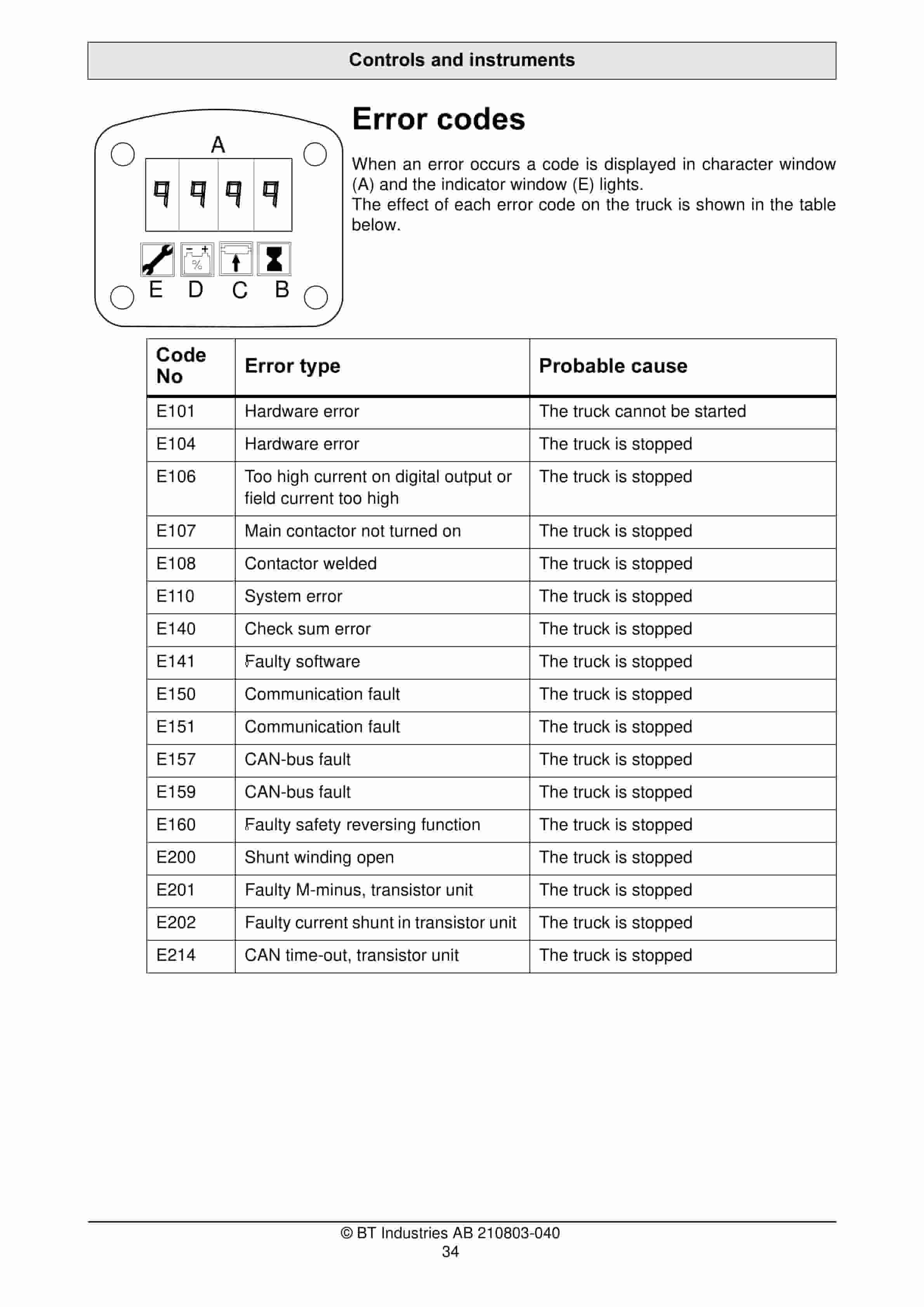
- 7.30. Error codes
- 7.30.1. Code No
- 7.30.2. Error type
- 7.30.3. Probable cause
- 8. Accessories
- 8.1. Platform
- 8.2. Load support
- 8.3. Integrated charger
- 8.4. Turtle button
- 9. Driving
- 9.1. Starting the truck
- 9.1.1. WARNING
- 9.1.2. WARNING
- 9.2. Braking
- 9.3. Deceleration
- 9.4. Steering
- 9.4.1. WARNING
- 9.5. Parking the truck
- 9.5.1. WARNING
- 10. Transporting loads
- 10.1. WARNING
- 10.2. WARNING
- 10.3. WARNING
- 10.4. WARNING
- 10.5. WARNING
- 10.6. WARNING
- 10.7. WARNING
- 10.8. Collecting a load
- 10.9. Depositing a load
- 10.10. Lift height limiting ASME
- 10.10.1. CAUTION
- 11. Battery
- 11.1. Changing the battery
- 11.1.1. WARNING
- 11.1.2. Proceed as follows to remove the discharged battery
- 11.1.2.1. WARNING
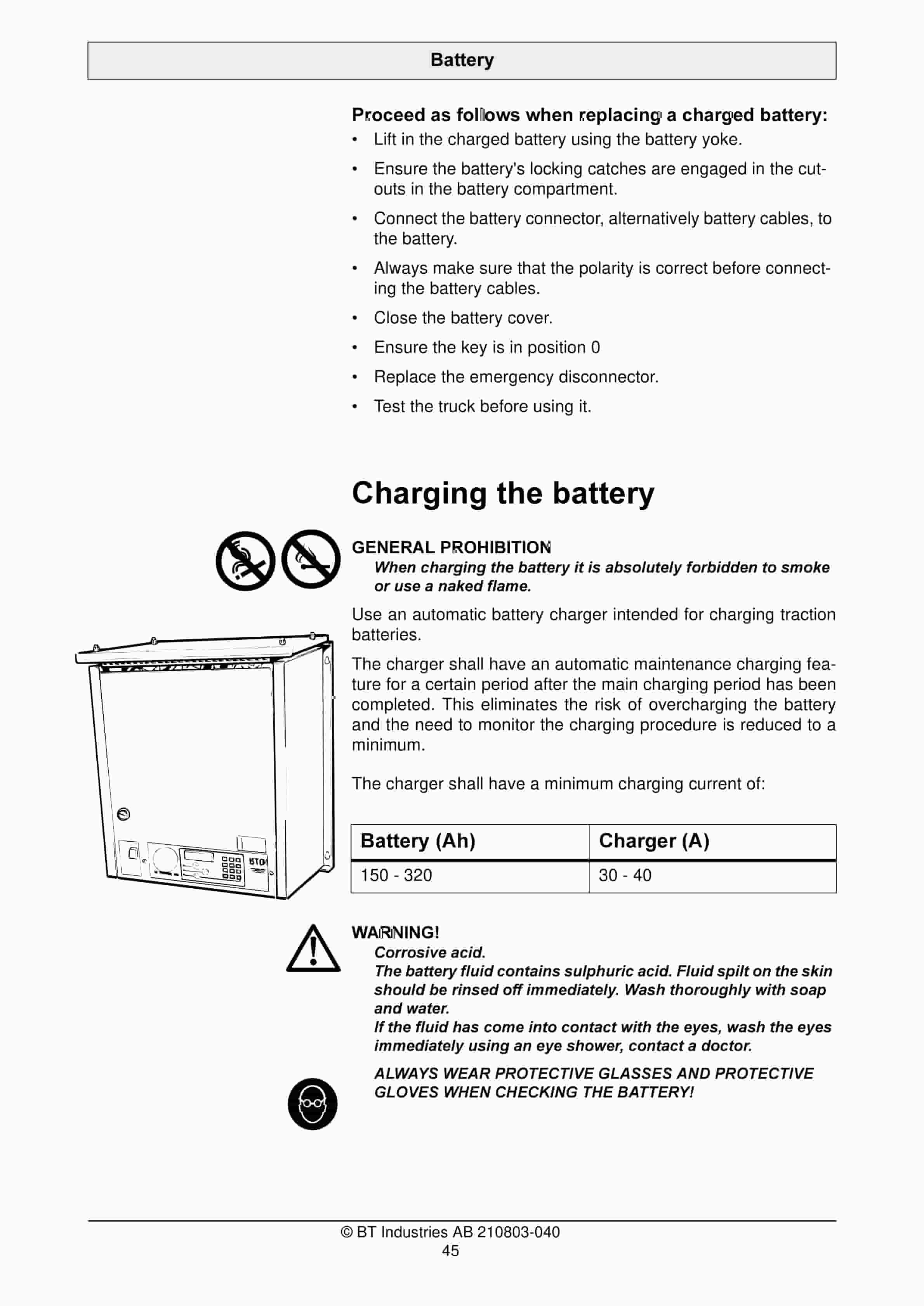
- 11.1.3. Proceed as follows when replacing a charged battery
- 11.2. Charging the battery
- 11.2.1. GENERAL PROHIBITION
- 11.2.2. Battery (Ah)
- 11.2.3. Charger (A)
- 11.2.3.1. WARNING
- 11.2.4. Before charging
- 11.2.4.1. WARNING
- 11.2.5. During charging
- 11.2.6. After charging
- 11.2.6.1. CAUTION
- 11.3. Battery maintenance
- 11.3.1. WARNING
- 11.3.2. Each week
- 11.3.3. Each month
- 11.3.3.1. Temperature C
- 11.3.3.2. Density g/cm3
- 12. Daily service and function checks
- 12.1. WARNING
- 12.2. Check points
- 13. Maintenance
- 13.1. Safety regulations with maintenance work
- 13.1.1. WARNING
- 13.1.2. WARNING
- 13.1.3. WARNING
- 13.1.4. WARNING
- 13.1.5. CAUTION
- 13.1.6. WARNING
- 13.2. Maintenance work that is to be carried out by the operator
- 13.3. Maintenance work that may be carried out by trained maintenance personnel
- 13.4. Cleaning and washing
- 13.4.1. External cleaning
- 13.4.2. Cleaning the motor compartment
- 13.4.3. Electrical components
- 13.5. Maintenance chart
- 13.5.1. Pos. no.
- 13.5.2. Work to carry out
- 13.5.2.1. Interval in hours – may vary due to application
- 13.5.2.2. Interval in days/weeks/months – may vary due to application
- 13.6. Lubrication chart
- 13.6.1. Service point
- 13.6.2. Interval/Running hours
- 13.6.3. Lubricant
- 13.7. Oil and grease specification
- 13.7.1. Lubricant
- 13.7.2. Specification
- 13.7.3. Application area
- 13.7.4. > – 15C
- 13.7.5. < – 15C
- 14. Transporting and storing the truck
- 14.1. The trucks dimensions and weight as standard
- 14.1.1. The trucks dimensions and weight
- 14.2. Lifting the truck
- 14.2.1. WARNING
- 14.2.2. WARNING
- 14.3. Towing and transporting a defective truck
- 14.3.1. WARNING
- 14.4. Storing the truck
- 14.4.1. Battery
- 14.4.2. Hydraulic system
- 14.4.3. Drive unit
- 14.5. Starting after a period of disuse
- 15. Recycling/discarding
- 15.1. Discarding the battery
- 15.2. Scrapping the truck
- 15.2.1. Chassis
- 15.2.2. Hydraulic system
- 15.2.3. Electrical system
- 16. typ 4 bt cert en.pdf
- 16.1. EC Declaration of Conformity
- 16.2. ______________________
Related products
-
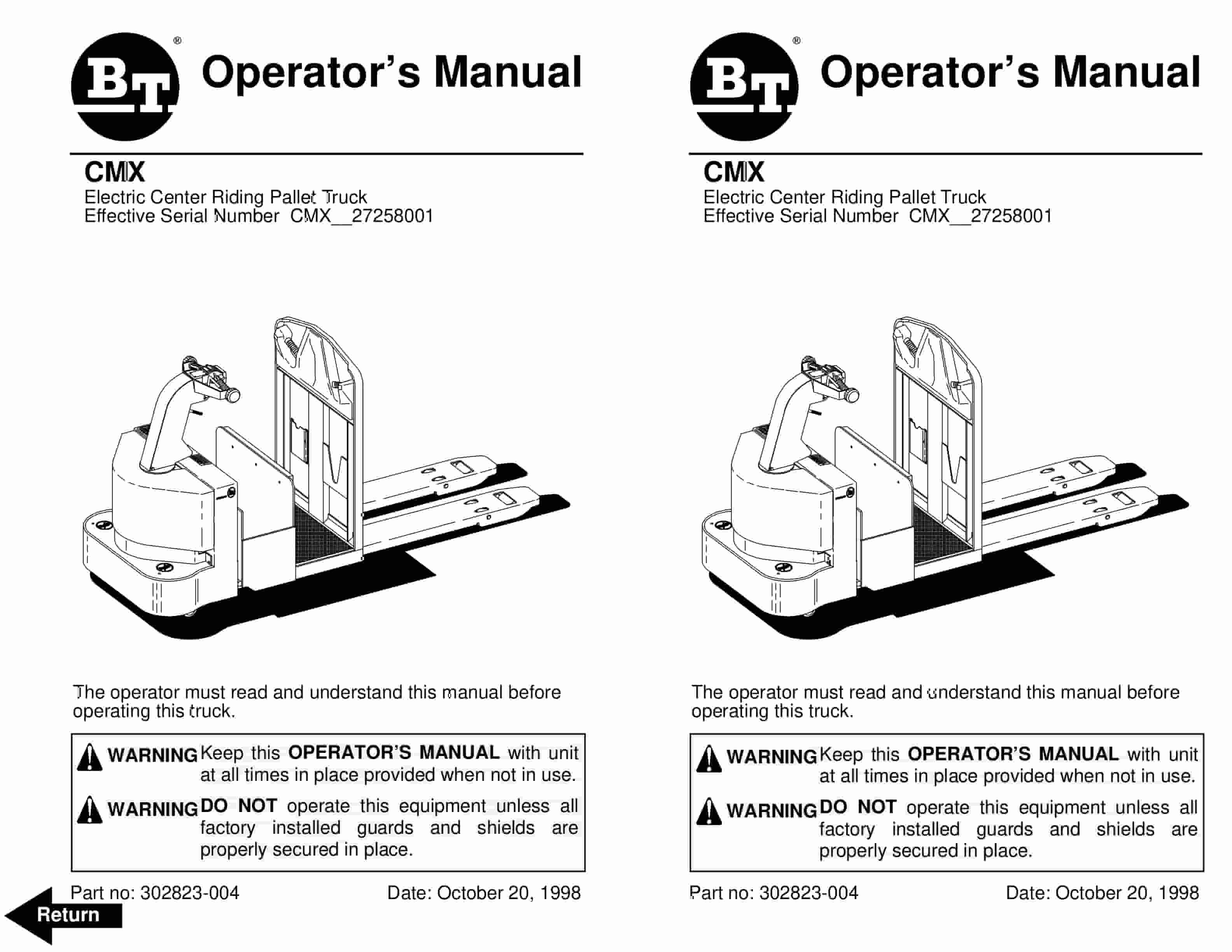
BT CMX Electric Center Riding Pallet Truck Operator Manual 302823-004
$30.00 Add to cart -
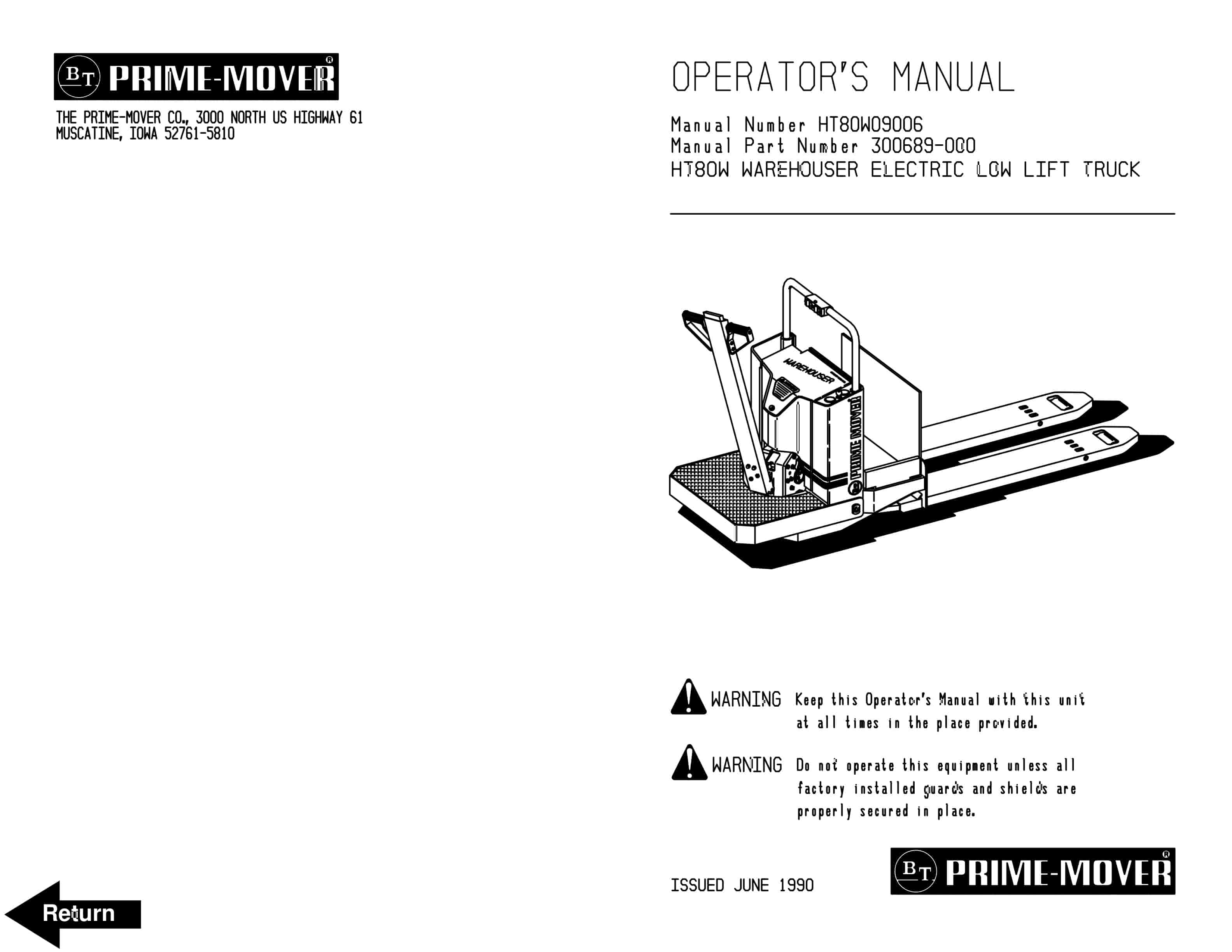
BT HT80W Warehouser Electric Low Lift Truck Operator Manual 300689-000
$30.00 Add to cart -
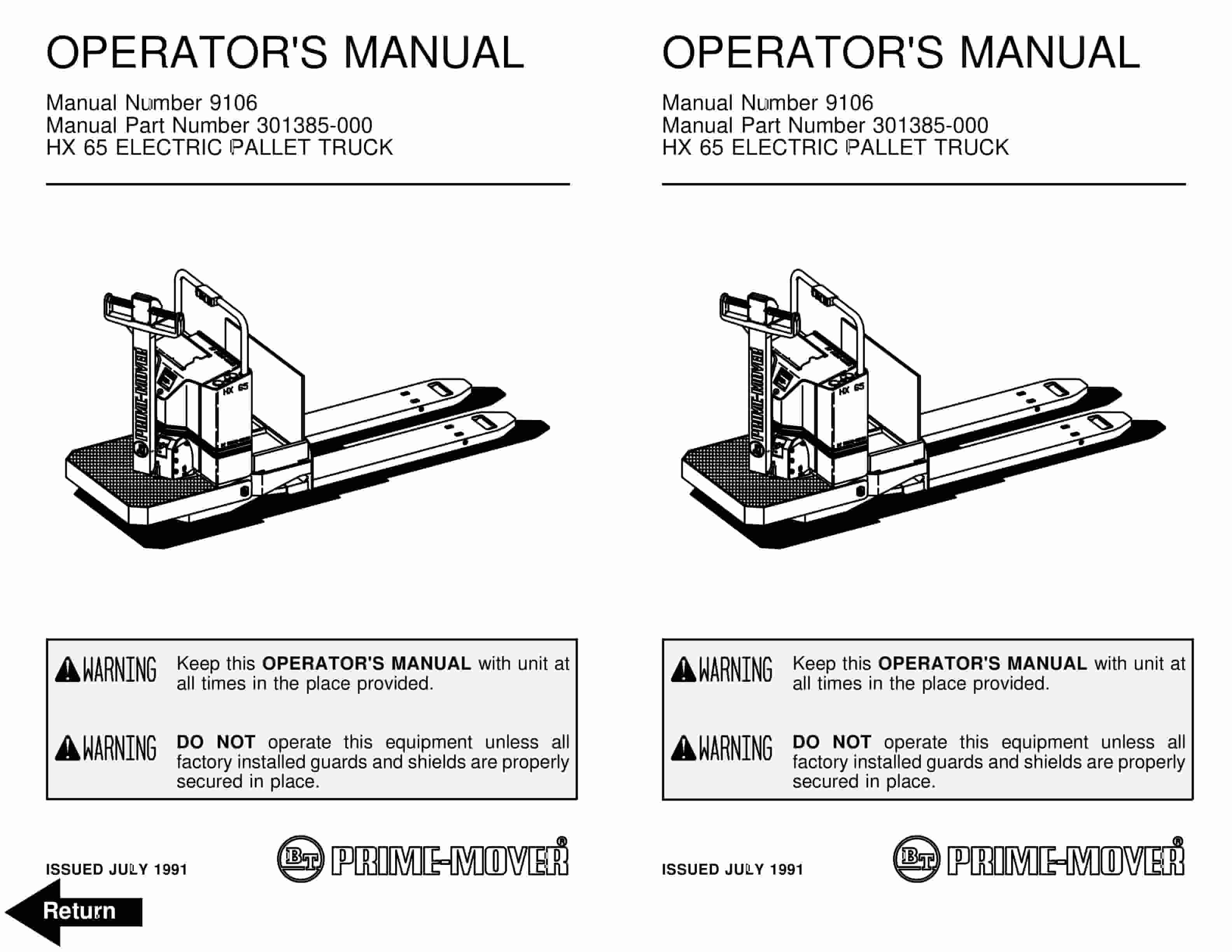
BT HX-65 Electric Pallet Truck Operator Manual 301385-000
$30.00 Add to cart -
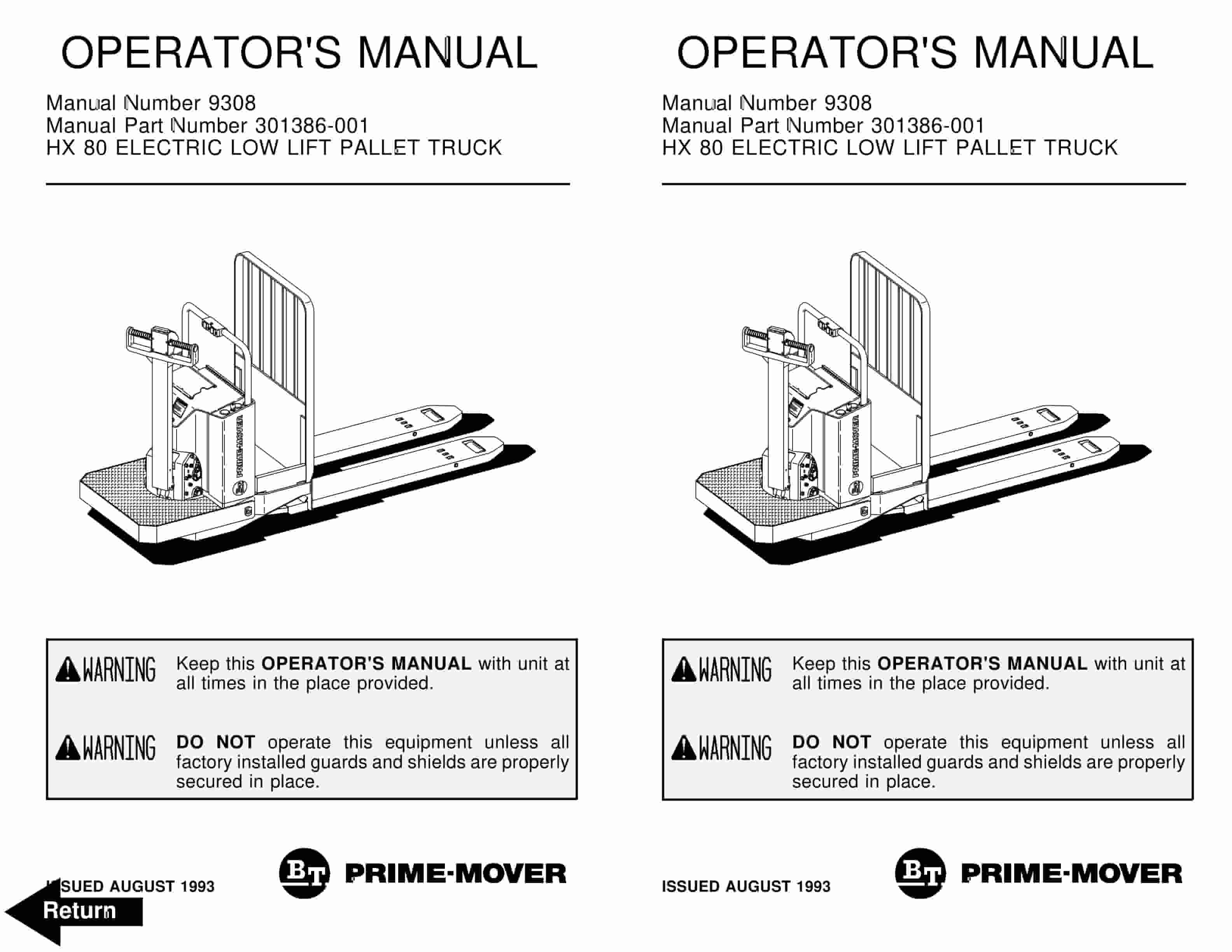
BT HX-80 Electric Low Lift Pallet Truck Operator Manual 301386-001
$30.00 Add to cart -
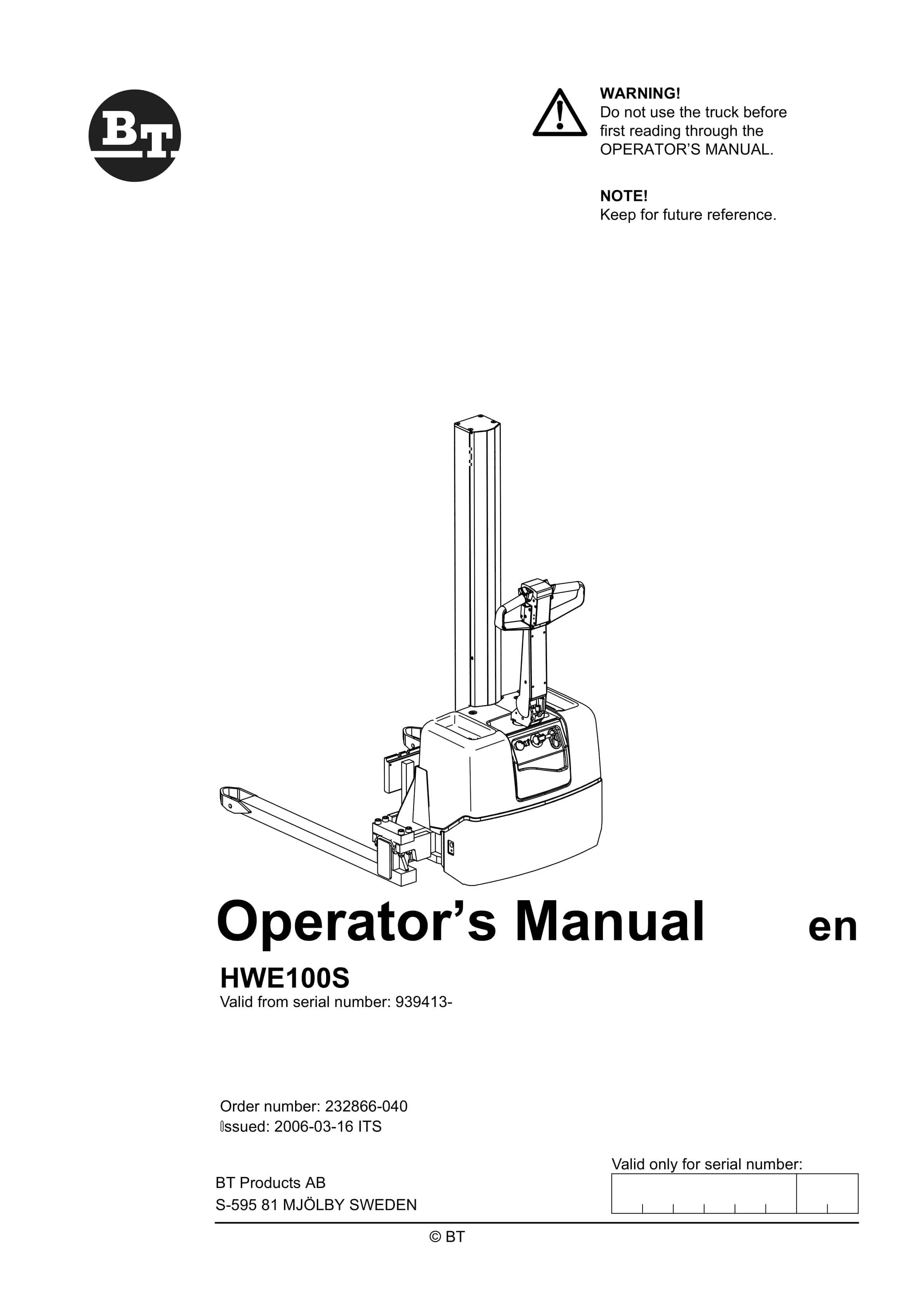
BT HWE100S Operator Manual 232866-040
$30.00 Add to cart


