

BT SL 2.0 Service Manual 170422-040
$30.00
- Type Of Manual: Service Manual
- Manual ID: 170422-040
- : Service Manual PDF
- Number of Pages: 92
- Size: 2.8MB
- Format: PDF
Product details
-
Model List:
- SL 2.0
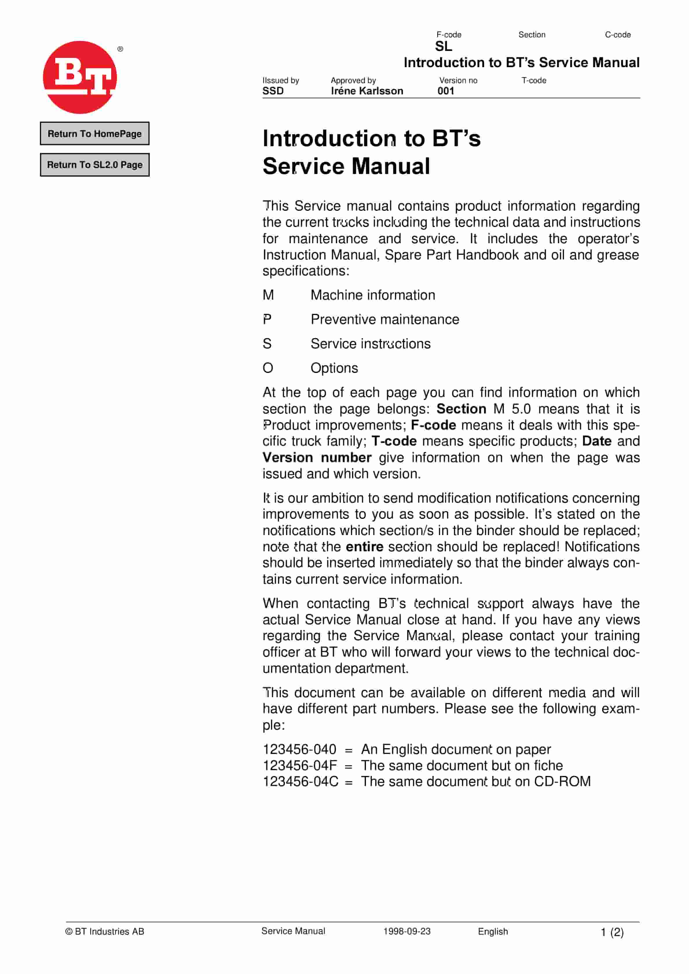
- 1. Introduction to BTs Service Manual
- 2. Contents Master Service Manual (MSM)
- 2.1. Valid from serial number
- 2.2. Serial No
- 2.3. Document list
- 2.3.1. Section
- 2.3.2. Document
- 3. Contents, M
- 3.1. Truck information
- 4. Operators manual
- 4.1. Valid from serial number
- 4.2. Serial No
- 4.3. General
- 4.3.1. Issued operators manuals
- 5. General product information
- 5.1. Valid from serial number
- 5.2. Serial No
- 5.3. Presentation of the truck
- 5.3.1. Intended application of the truck
- 5.3.2. Forbidden application of the truck
- 5.4. Truck data
- 5.4.1. Truck type
- 5.5. Truck dimensions
- 5.5.1. Dimensions (mm)
- 5.6. Main components
- 5.6.1. Control console Steering, raise/lower, signal, travel direction, accelerator/ brake, and all …
- 5.6.2. Identification plate With model designation, serial number, year of manufacture, weight witho…
- 5.6.3. Serial number The serial number plate fitted to the chassis.
- 5.6.4. Cover Easily swivelled to provide good access for servicing.
- 5.6.5. Pedal Safety pedal with automatic parking brake.
- 5.6.6. Left foot pedal Safety pedal for the left foot.
- 5.6.7. Drive motor fuse 160A, BT part no. 29223.
- 5.6.8. Pump motor fuse 200A, BT part no. 29673.
- 5.6.9. Control circuit fuse 10A, BT part no. 122308-100.
- 5.6.10. Fuse for electrical steering wheel 20A BT part no.122308-200.
- 5.6.11. Electronics All the electronics are located together in a protected area of the motor.
- 5.6.12. Electrical steering motor Mounted with the drive gear to provide a compact design.
- 5.6.13. Battery 24V with different Ah values.
- 5.6.14. Recharging connector The battery is recharged via this permanently attached recharging conne…
- 5.6.15. Hydraulic unit Pump motor, pump, valve and oil tank.
- 5.6.16. Drive unit with brake Drive motor, gears and drive wheel integrated in a compact unit. Steer…
- 5.7. Warning and information plates and symbols
- 5.7.1. Identification plate
- 5.7.2. Modification plate
- 5.7.3. Serial number
- 5.7.4. Hydraulic oil filling
- 5.7.5. Lifting points
- 5.7.6. Travel control
- 5.7.7. Brake control
- 5.7.8. Horn
- 5.7.9. Hydraulic control Lifting/Lowering
- 6. Technical Service Data
- 6.1. Valid from serial number
- 6.2. Serial No
- 6.2.1. Drive motor
- 6.2.2. Transmission/gear
- 6.2.3. Hydraulic system
- 6.2.4. Steering motor
- 6.2.5. Battery
- 6.2.6. Lifting/lowering speed
- 6.2.7. Power consumption
- 7. Ordering Spare Parts
- 8. Quality Parts
- 8.1. Valid from serial number
- 8.2. Serial No
- 8.3. Issued Quality Parts
- 8.3.1. Serial No
- 8.3.2. Order number
- 9. Content, P
- 9.1. Preventive Maintenance
- 10. Introduction, maintenance
- 10.1. Safety regulations with maintenance work
- 10.1.1. WARNING
- 10.1.2. WARNING
- 10.1.3. WARNING
- 10.1.4. CAUTION
- 10.2. Cleaning and washing
- 10.2.1. External cleaning
- 10.2.2. Cleaning the motor compartment
- 10.2.3. Electrical components
- 10.3. Safe lifting of the truck
- 10.3.1. WARNING
- 11. Service schedule
- 11.1. Valid from serial number
- 11.2. Serial No
- 11.3. Maintenance chart
- 11.3.1. Pos. no.
- 11.3.2. Work to carry out
- 11.4. Lubrication chart
- 11.4.1. Service point
- 11.4.2. Interval/Running hours
- 11.4.3. Lubricant
- 12. Oil and grease specification
- 12.1. Valid from serial number
- 12.2. Serial No
- 12.3. Lubricant
- 12.4. Specification
- 12.5. Application area
- 12.6. > – 15C
- 12.7. < – 15C
- 13. Content, S
- 13.1. Service instructions
- 14. Electro magnetic brake
- 14.1. Valid from machine number
- 14.2. Serial No
- 14.3. General description
- 14.4. Main components of the brake
- 14.4.1. Description
- 14.5. Maintenance
- 14.6. Adjustment of gap
- 14.6.1. Loosen the tension of the three mounting bolts (1).
- 14.6.2. Turn the lock nuts (2) anti-clockwise and tighten the bolts slightly while checking the gap in…
- 14.6.3. Tighten the mounting bolts 25 Nm and recheck the gap with the feeler gauge.
- 14.7. Optimising the brake system
- 14.7.1. Adjusting the change between the brake stages
- 14.7.2. Adjusting of the first brake stage
- 14.7.3. Adjusting of the second brake stage
- 14.8. Exchange of brake disc
- 14.8.1. Exchange procedure
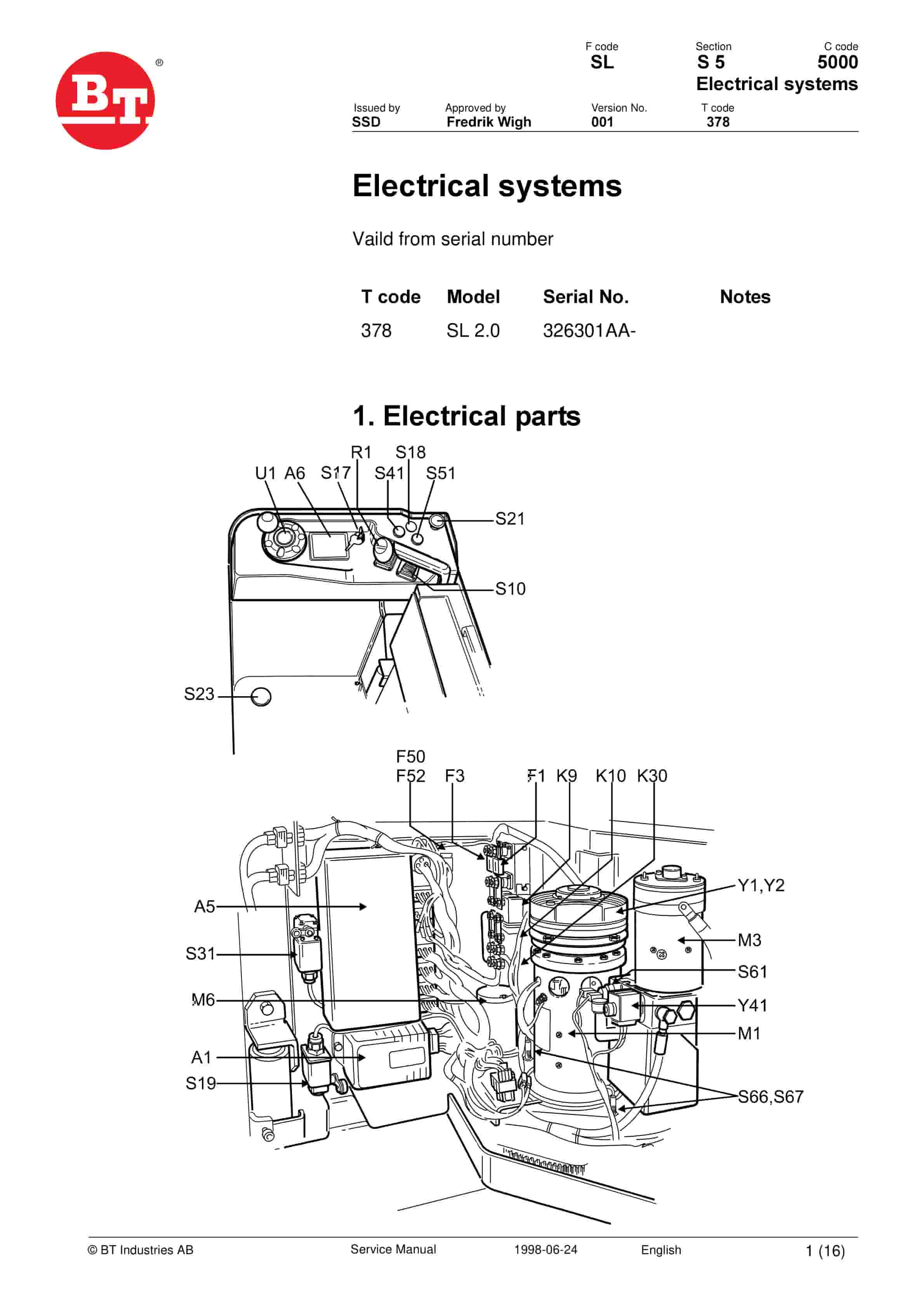
- 15. Electrical systems
- 15.1. Serial No.
- 15.2. Electrical parts
- 15.3. List of symbols and electrical wir- ing diagram
- 15.3.1. Description
- 15.3.2. Function
- 15.3.3. Electrical wiring diagram (1/5)
- 15.3.4. Electrical wiring diagram (2/5)
- 15.3.5. Electrical wiring diagram (3/5)
- 15.3.6. Electrical wiring diagram (4/5)
- 15.3.7. Electrical wiring diagram (5/5)
- 15.4. Functional description
- 15.4.1. General
- 15.4.2. Key in position 0
- 15.4.3. Key in position I
- 15.4.4. Driving in the drive wheel direction
- 15.4.5. Driving in the fork direction
- 15.4.6. Motor braking and reversing
- 15.4.7. Braking
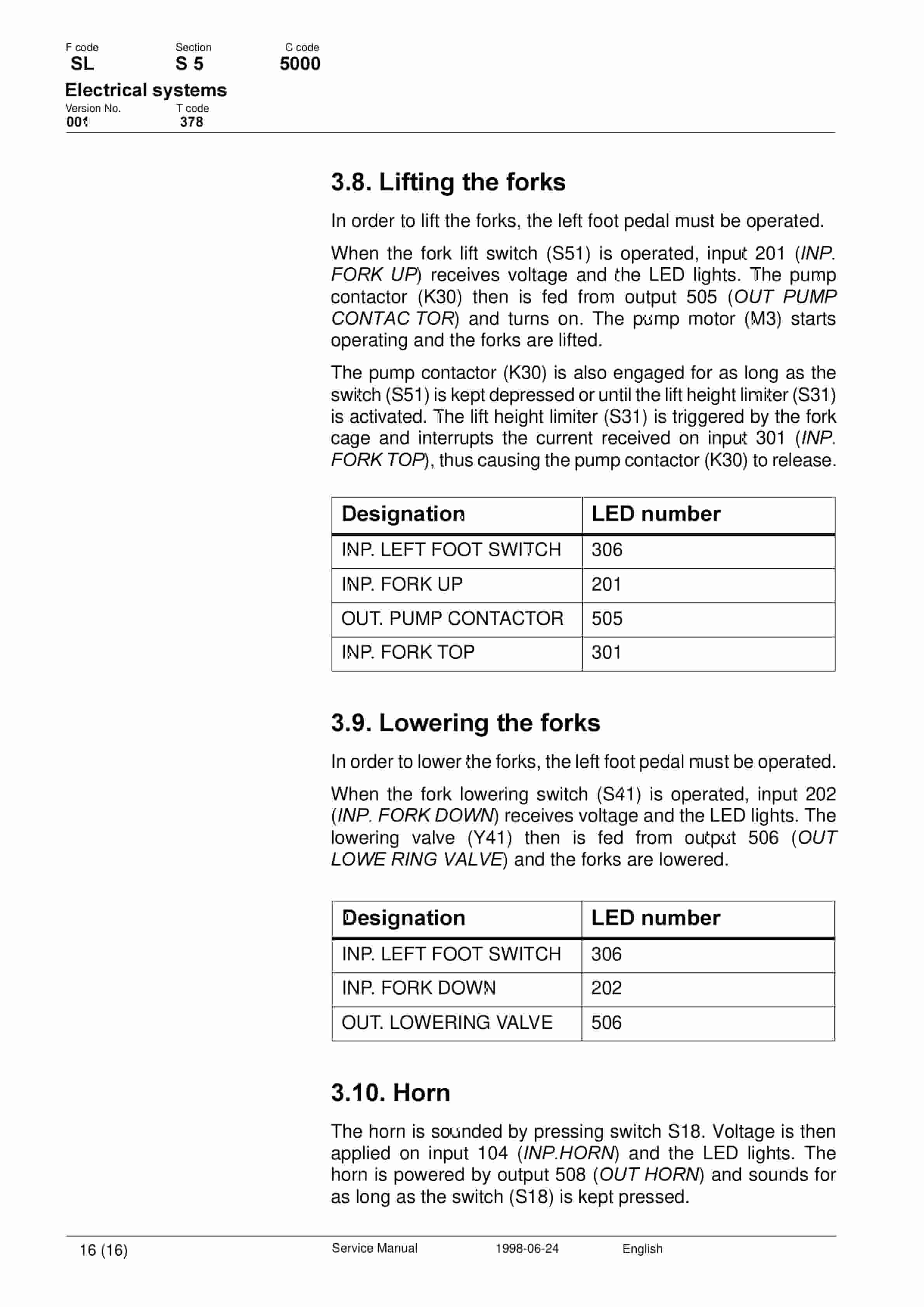
- 15.4.8. Lifting the forks
- 15.4.9. Lowering the forks
- 15.4.10. Horn
- 16. Transistor panel
- 16.1. Valid from serial number
- 16.2. Serial No.
- 16.3. General
- 16.4. Connectors
- 16.4.1. Connector
- 16.4.2. Function
- 16.4.3. Logic connector
- 16.5. Parameters
- 16.5.1. Parameter
- 16.5.2. Standard value
- 16.5.3. Explanation
- 16.5.4. Mode 1 and 2
- 16.6. Diagnosing and troubleshooting
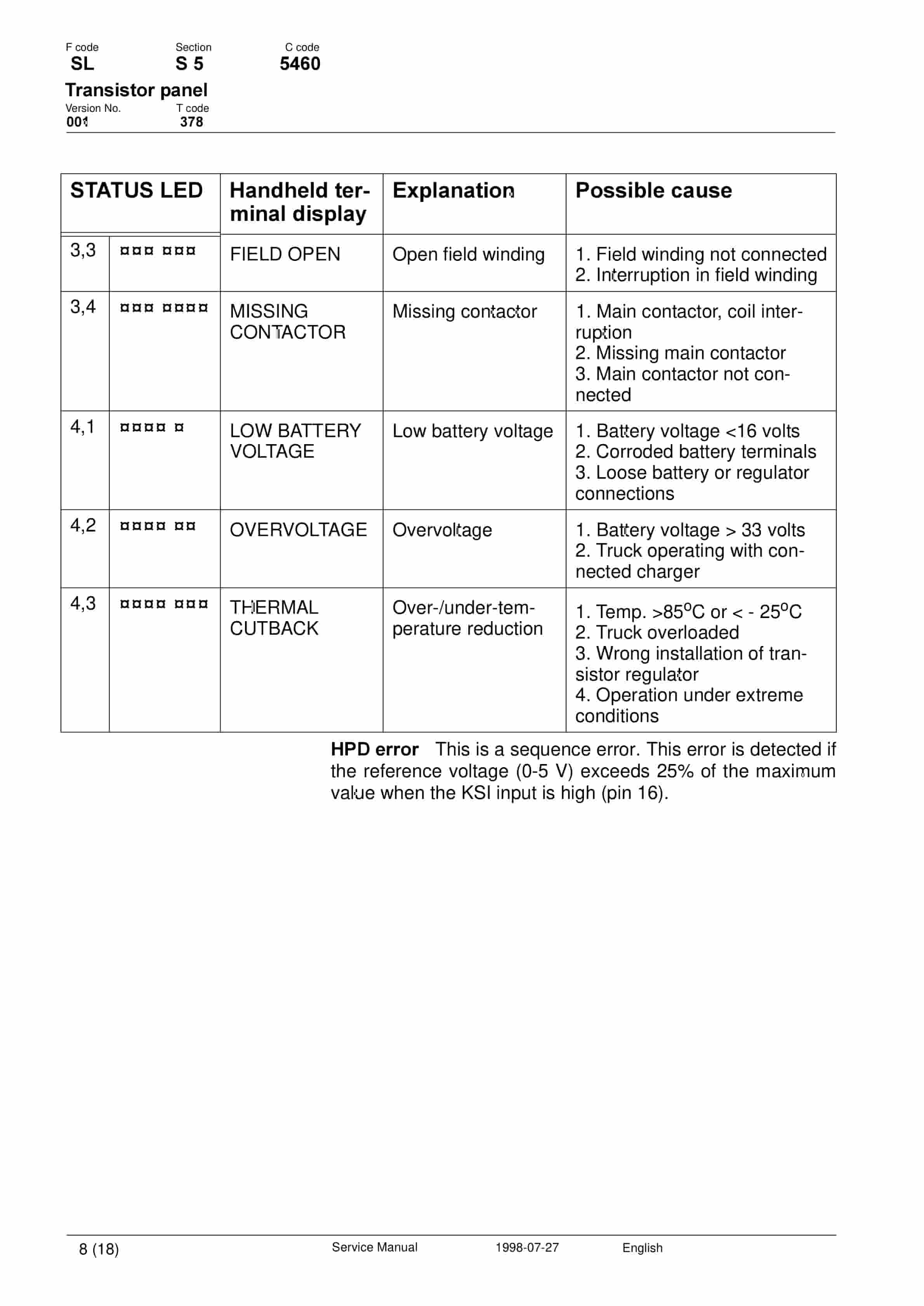
- 16.6.1. Display of error codes and error logging
- 16.6.2. Error codes and troubleshooting
- 16.6.3. Resetting errors
- 16.7. Maintenance
- 16.7.1. Safety
- 16.7.2. Cleaning
- 16.8. Technical specifications Curtis 1243
- 16.8.1. Explanation
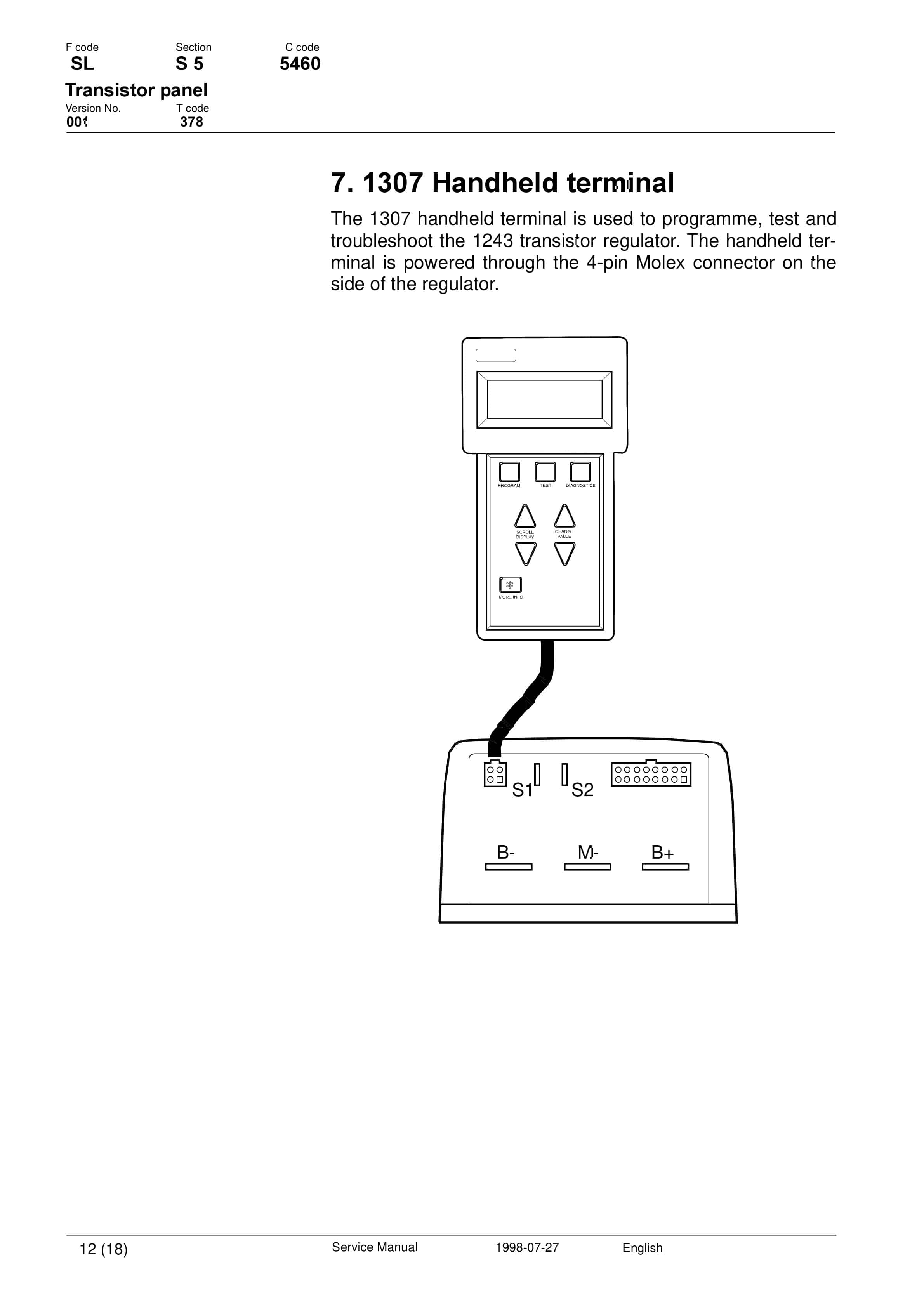
- 16.9. Handheld terminal
- 16.9.1. Function
- 16.9.2. Explanation
- 16.10. Using the handheld terminal
- 16.10.1. Checking and adjusting parameters
- 16.10.2. SPECIAL PROGRAM MODE
- 16.10.3. Using the TEST mode
- 16.10.4. Using the DIAGNOSTICS MODE
- 16.10.5. SPECIAL DIAGNOSTICS MODE
- 17. Electronic card
- 17.1. Valid from machine number
- 17.1.1. Truck No
- 17.2. General description
- 17.3. Parameter settings
- 17.3.1. Parameter
- 17.3.2. Setting the battery size/type
- 17.4. Card pin connections and leds
- 17.4.1. Terminal no.
- 17.4.2. LED no.
- 17.4.3. Signal name
- 17.4.4. Function
- 17.5. Error codes
- 17.5.1. Code No.
- 17.5.2. Error type
- 17.5.3. Display
- 17.5.4. Effect on the truck
- 18. Hydraulic/pneumatic system
- 18.1. Valid from serial number
- 18.2. Serial No.
- 18.3. General
- 18.4. Hydraulic diagram
- 18.4.1. List of symbols
- 18.5. Functional description
- 18.5.1. Lifting the forks
- 18.5.2. Lowering the forks
- 18.5.3. Pressure guard S61
Related products
-
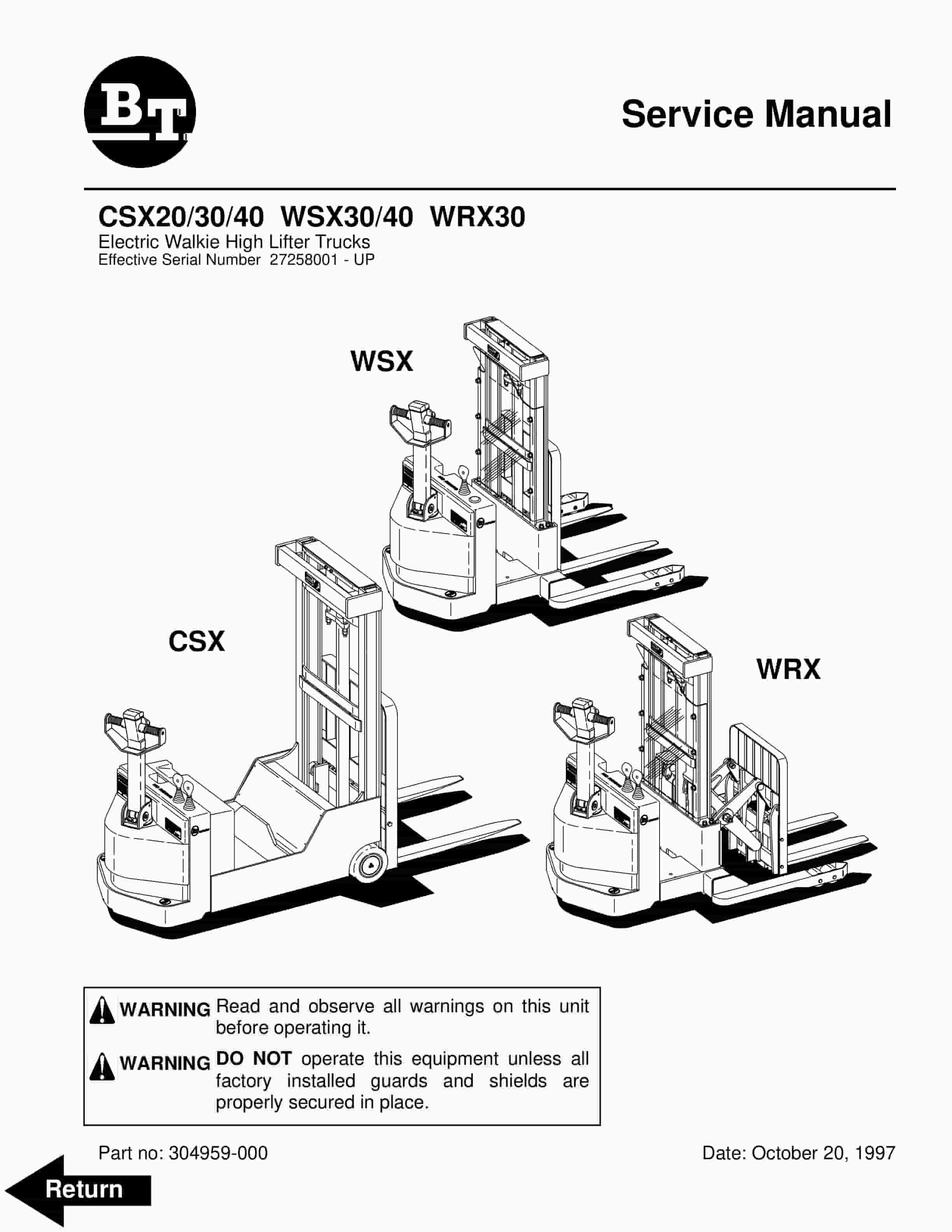
BT CSX20, CSX30, CSX40, WSX30, WSX40, WRX30 Electric Walkie High Lifter Truck Service Manual 304959-000
$30.00 Add to cart -
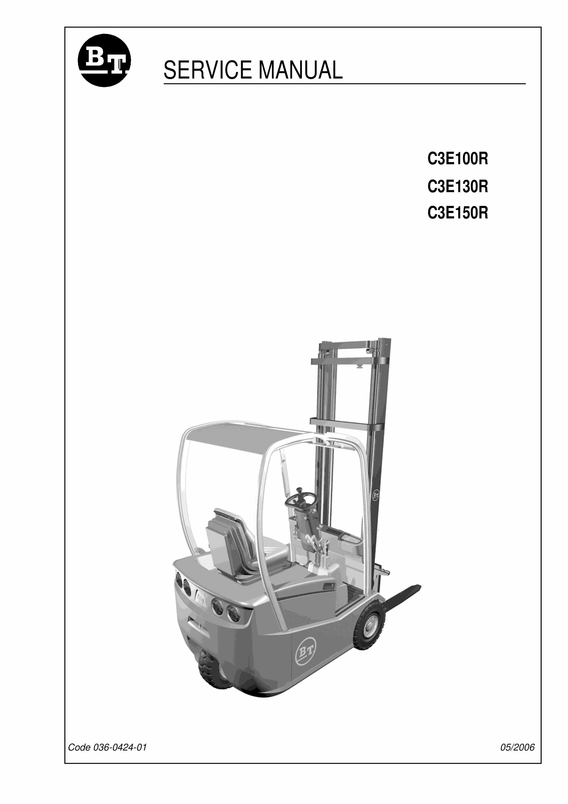
BT C3E130R, C3E150R, C3E100R Service Manual 036-0424-01
$30.00 Add to cart -
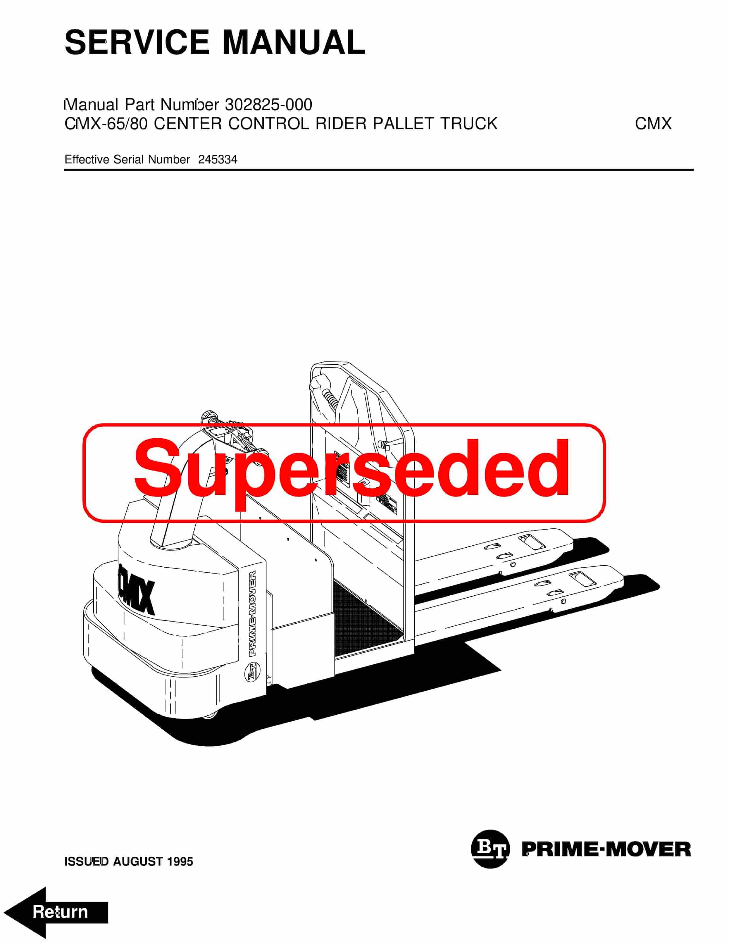
BT CMX-65, CMX-80 Center Control Riding Pallet Truck Service Manual 302825-000
$30.00 Add to cart -
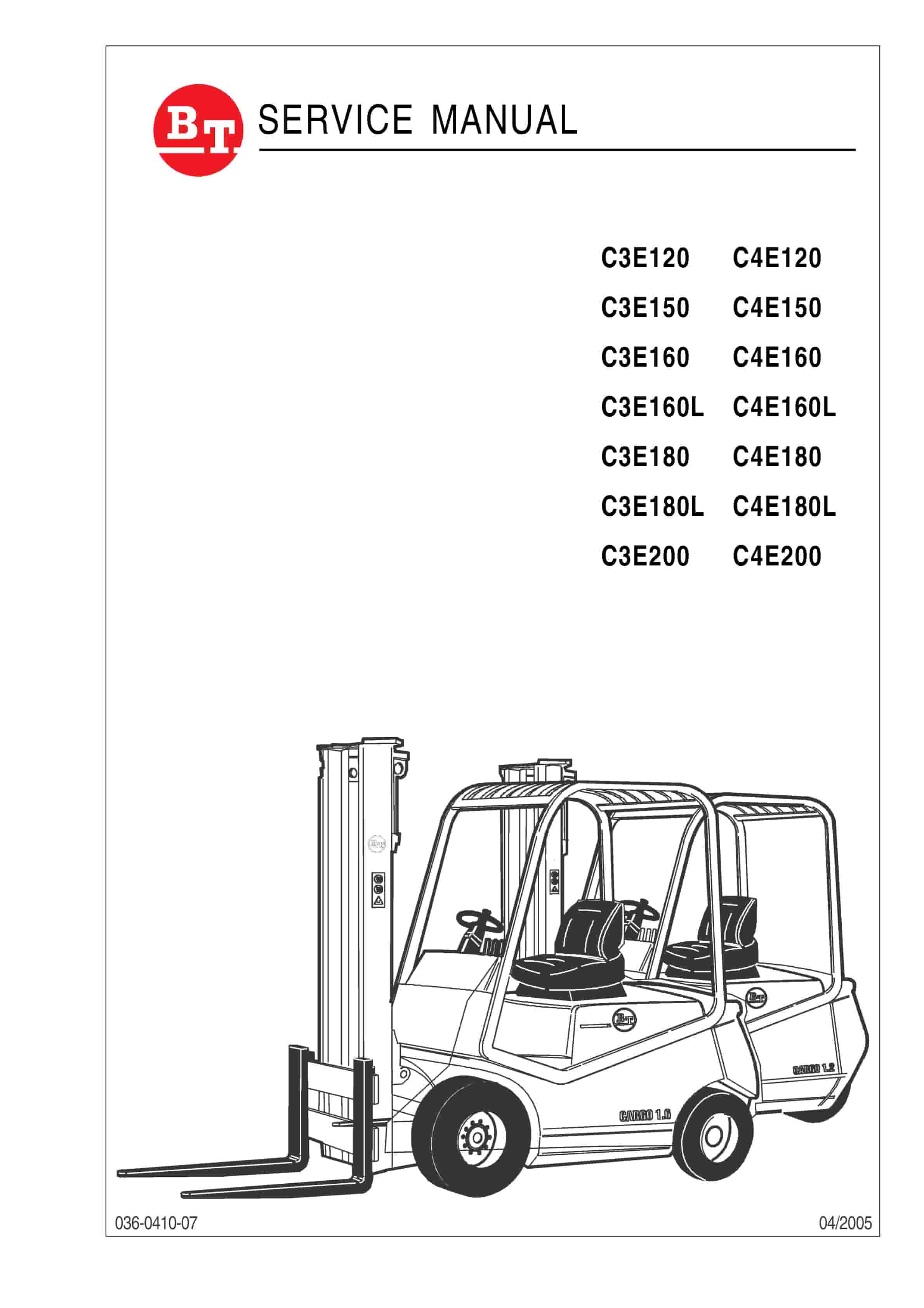
BT C3E120 to C4E200 Service Manual 036-0410-07
$30.00 Add to cart -
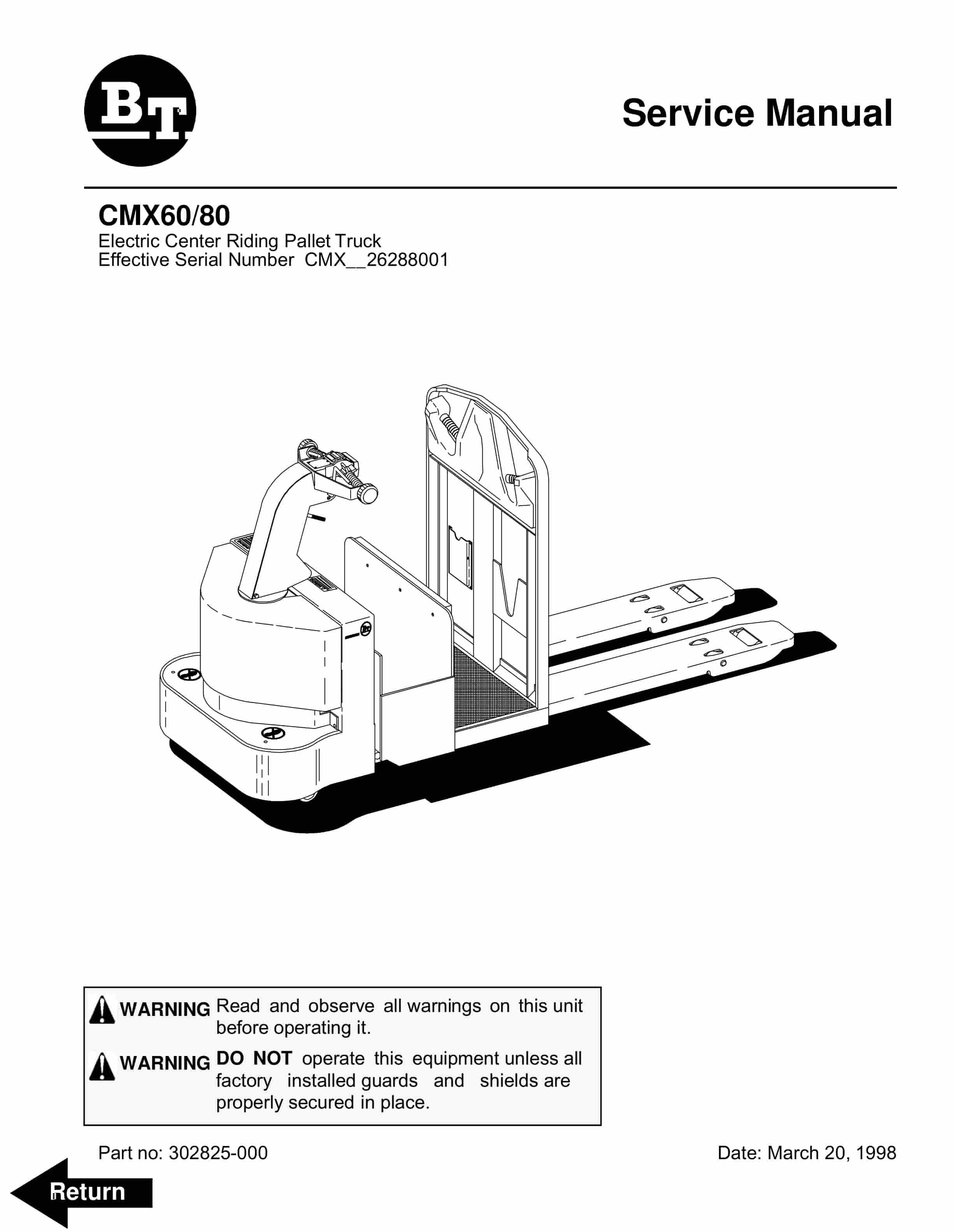
BT CMX60, CMX80 Electric Center Riding Pallet Truck Service Manual 302825-000
$30.00 Add to cart


