


BT SPE120, SPE120L, SPE140, SPE140L, SPE140S, SPE160, SPE160L, SPE200, SPE200D, SPE200L Repair Manual 7590353
$30.00
- Type Of Manual: Repair Manual
- Manual ID: 7590353
- : Service Manual PDF
- Number of Pages: 644
- Size: 116.6MB
- Format: PDF
Category: BT Service Manual PDF
-
Model List:
- SPE120, SPE120L, SPE140, SPE140L, SPE140S, SPE160, SPE160L, SPE200, SPE200D, SPE200L
- 1. General introduction
- 1.1. How to use this manual
- 1.2. Warning levels and symbols
- 1.3. Pictograms
- 2. General safety rules
- 2.1. Authorised personnel
- 2.2. Work safety
- 2.3. Electrical system
- 2.3.1. Electrostatic risks
- 2.3.2. Battery handling
- 2.4. Safe lifting
- 2.5. Truck modifications
- 2.6. Software
- 2.7. Hydraulic system
- 3. Operating principle
- 3.1. Description
- 3.1.1. Battery is connected
- 3.1.2. Login via keypad
- 3.1.3. Login via ID key option
- 3.1.4. Tiller arm lowered for driving
- 3.1.5. Driving in fork direction
- 3.1.6. Driving in the drive wheel direction
- 3.1.7. Braking in neutral
- 3.1.8. Reverse braking
- 3.1.9. Mechanical braking
- 3.1.10. Emergency reversal
- 3.1.11. Fork lowering
- 4. Parameters
- 4.1. Display/change parameters
- 4.2. Parameters in general
- 4.3. Parameter list
- 4.4. Parameter list
- 5. Installation
- 5.1. Transport
- 5.1.1. Transporting the truck
- 5.1.2. Transporting the mast
- 5.2. Lifting the truck
- 5.2.1. Lifting the truck
- 5.2.2. Lift using a jack
- 5.3. Commissioning
- 5.3.1. Parameters on commissioning
- 5.3.1.1. Setting parameters
- 5.3.1.2. Setting collision sensor parameters (option)
- 5.3.1.3. Setting battery parameters
- 5.3.2. Battery
- 5.3.2.1. Battery installation
- 5.3.2.2. Placement of signs
- 5.3.2.3. Placement of signs
- 5.3.2.4. Placement of signs
- 5.3.2.5. Placement of signs
- 6. Troubleshooting
- 6.1. Auxiliary functions
- 6.1.1. Towing a defective truck
- 6.1.1.1. Towing and transporting a defective truck
- 6.1.2. Emergency driving mode
- 6.1.2.1. Emergency driving mode
- 6.1.3. Error code history
- 6.1.3.1. Error code history
- 6.1.4. Extended error log
- 6.1.4.1. Extended error log
- 6.1.5. Built-in test function for the tiller arm
- 6.1.5.1. General
- 6.1.5.2. Display test
- 6.1.5.3. Speed control
- 6.1.5.4. Safety reversing
- 6.1.5.5. Controls for lifting/lowering
- 6.1.5.6. Sensilift
- 6.1.5.7. Keypad
- 6.2. Initial troubleshooting
- 6.3. Concluding troubleshooting
- 6.4. Troubleshooting using error codes
- 6.4.1. List of error codes
- 7. Chassis C0000
- 7.1. Overview
- 7.2. Frame, chassis C0300
- 7.2.1. Inspection covers C0340
- 7.2.1.1. Motor compartment covers
- 7.2.2. Support arms, stabilizers C0350
- 7.2.2.1. Overview
- 7.2.2.2. Checking the linkage
- 7.2.2.3. Checking the wheel fork flexibility
- 7.2.2.4. Replacing the pressure rod
- 7.2.2.5. Replacing torsion tubes
- 7.2.2.6. Replacing the roller on the torsion tube
- 7.2.2.7. Replacing a wheel fork
- 7.2.2.8. Replacing a bogie link, fork wheel
- 7.2.2.9. Replacing a bogie link, support arm
- 7.2.2.10. Replacing the wheel fork bushing
- 7.2.2.11. Replacing the support arm bushing
- 7.2.3. Fork structure (low-lifter) C0380
- 7.2.3.1. Checking the fork lift height limitation
- 7.2.4. Battery compartment parts C0390
- 7.2.4.1. Overview
- 7.2.4.2. Overview
- 7.2.4.3. Description
- 7.3. Frame/chassis components C0400
- 7.3.1. Motor mount/brackets C0450
- 7.3.1.1. Checking the motor mounts
- 7.3.1.2. Drive unit mountings
- 7.3.1.3. PowerTrak
- 7.3.1.4. Decompression locking
- 7.4. Operator compartment, cab C0500
- 7.4.1. Platform including fixing points C0560
- 7.4.1.1. Overview
- 7.4.1.2. Overview
- 7.4.1.3. Overview
- 7.4.1.4. Checking the function of the platform switches
- 7.4.1.5. Adjusting the position sensor B120
- 7.4.1.6. Checking the platform
- 7.4.1.7. Inspection of the rear chassis
- 7.4.1.8. Gas strut
- 7.4.1.9. Platform suspension
- 7.4.1.10. Safety switch, platform B119
- 7.4.1.11. Safety switch, platform B119/B120
- 7.4.1.12. Replacing the platform
- 7.5. Safety equipment C0800
- 7.5.1. Operator protection C0840
- 7.5.1.1. Fixed side guard
- 7.5.1.2. Gate
- 7.5.1.3. Back rest
- 7.5.2. Signs, warnings, labels C0850
- 7.5.2.1. Checking signs and labels
- 7.5.2.2. Placement of signs
- 7.5.2.3. Placement of signs
- 7.5.2.4. Placement of signs
- 7.5.2.5. Placement of signs
- 8. Motors C1000
- 8.1. Electric motors C1700
- 8.1.1. Electric pump motor C1710
- 8.1.1.1. Overview
- 8.1.1.2. Replacing the pump motor
- 8.1.2. Electric steering motor C1730
- 8.1.2.1. Overview
- 8.1.2.2. Description
- 8.1.2.3. Cleaning the ring gear
- 8.1.2.4. Checking the electrical connections
- 8.1.2.5. Checking the steering motor gears
- 8.1.2.6. Checking the steering motor
- 8.1.2.7. Lubricating the ring gear
- 8.1.2.8. Check the drive gears attachment
- 8.1.2.9. Replacing the steering motor
- 8.1.3. Electric fan motor/fan C1740
- 8.1.3.1. Overview
- 8.1.3.2. Description
- 8.1.3.3. Replacing the motor control fan
- 8.1.4. Electric drive motor C1760
- 8.1.4.1. Overview 1.8, 2.5 kW
- 8.1.4.2. Overview
- 8.1.4.3. Description
- 8.1.4.4. Check the rotational speed sensor fitting
- 8.1.4.5. Checking the electrical connections
- 8.1.4.6. Checking the drive motor
- 8.1.4.7. Listen for any abnormal noise in the drive motor bearings
- 8.1.4.8. Check the drive motor fitting (1.8 and 2.5 kW)
- 8.1.4.9. Check the drive motor fitting (2.8 kW)
- 8.1.4.10. Checking the rotational speed sensor
- 8.1.4.11. Replacing the drive motor
- 8.1.4.12. Replacing the temperature sensor
- 8.1.4.13. Replacing the rotational speed sensor
- 8.1.4.14. Replacing the toothed wheel
- 9. Transmission/Drive gear C2000
- 9.1. Drive unit, final gear C2500
- 9.1.1. Drive unit/gear C2550
- 9.1.1.1. Overview
- 9.1.1.2. Overview
- 9.1.1.3. Description
- 9.1.1.4. Check the drive gears attachment
- 9.1.1.5. Checking for leaks in the drive gear
- 9.1.1.6. Checking for noise in the drive gear
- 9.1.1.7. Replacing the drive gear
- 9.1.1.8. Replacing the wheel hub seal
- 9.1.1.9. Drive gear oil change
- 9.1.1.10. Replacing the drive gear steering bearing
- 9.1.1.11. Stud replacement
- 10. Brake/wheel/track system C3000
- 10.1. Travel brake system C3100
- 10.1.1. Description
- 10.1.1.1. Brake types
- 10.2. Parking brake details C3300
- 10.2.1. Electrical parking brake, magnet brake C3370
- 10.2.1.1. Overview
- 10.2.1.2. Description
- 10.2.1.3. Cleaning the parking brake
- 10.2.1.4. Adjusting the parking brake gap
- 10.2.1.5. Adjusting the parking brake gap
- 10.2.1.6. Adjusting the parking brake gap
- 10.2.1.7. Adjusting the parking brake gap
- 10.2.1.8. Tighten the parking brake mounting bolts
- 10.2.1.9. Emergency release of the parking brake
- 10.2.1.10. Checking the parking brake
- 10.2.1.11. Replacing the brake hub
- 10.2.1.12. Replacing the friction disc
- 10.2.1.13. Replacing the parking brake
- 10.3. Wheels C3500
- 10.3.1. Drive wheel C3530
- 10.3.1.1. Overview
- 10.3.1.2. Description
- 10.3.1.3. Measuring the drive wheel tread
- 10.3.1.4. Measuring the drive wheel tread
- 10.3.1.5. Replacing the drive wheel
- 10.3.2. Support arm wheels/castor wheels C3540
- 10.3.2.1. Overview
- 10.3.2.2. Description
- 10.3.2.3. Cleaning castor wheels
- 10.3.2.4. Measuring the castor wheel tread
- 10.3.2.5. Measuring the castor wheel tread
- 10.3.2.6. Measuring the castor wheel tread
- 10.3.2.7. Measuring the castor wheel tread
- 10.3.2.8. Checking the castor wheels
- 10.3.2.9. Replacing the castor wheel
- 10.3.2.10. Replacing the castor wheel assembly
- 10.3.3. Fork wheels/support arm wheels C3550
- 10.3.3.1. Overview
- 10.3.3.2. Description
- 10.3.3.3. Cleaning the fork wheels
- 10.3.3.4. Measuring the fork wheel tread
- 10.3.3.5. Checking the fork wheel mounting
- 10.3.3.6. Checking the fork wheel bushings
- 10.3.3.7. Replacing a single wheel
- 10.3.3.8. Replacing bogie wheels
- 10.3.3.9. Replacing a bogie link
- 11. Steering system C4000
- 11.1. Description
- 11.1.1. Power steering
- 11.2. Mechanical steering system C4100
- 11.2.1. Steering arm/wheel/lever C4110
- 11.2.1.1. Overview tiller arm
- 11.2.1.2. Operating panel
- 11.2.1.3. Tiller arm handle
- 11.2.1.4. Tiller arm
- 11.2.1.5. Steering yoke
- 11.2.1.6. Steering adapter
- 11.2.1.7. Tiller arm wiring harness
- 11.2.1.8. Replacing the steering bearing
- 11.2.1.9. Replacing the rubber seals
- 11.3. Electric steering system C4300
- 11.3.1. Overview
- 11.3.2. Steering angle sensor C4350
- 11.3.2.1. Description
- 11.3.2.2. Replacing the steering angle sensor servo unit.
- 11.3.2.3. Checking the reference sensor
- 11.3.2.4. Replacing the steering damper
- 12. Electrical system C5000
- 12.1. Description
- 12.1.1. General
- 12.1.2. Truck firmware applications
- 12.2. Software update
- 12.3. Programming tools
- 12.3.1. TruckCom
- 12.3.1.1. Connect the CAN interface to the truck
- 12.3.2. Software
- 12.3.2.1. Software update
- 12.4. General electric equipment C5100
- 12.4.1. Battery C5110
- 12.4.1.1. Cleaning the battery
- 12.4.1.2. Checking the connections
- 12.4.1.3. Checking the battery cables
- 12.4.1.4. Checking the battery
- 12.4.1.5. Checking cell and terminal protectors
- 12.4.1.6. Checking the level of the electrolyte
- 12.4.1.7. Checking the electrolyte density
- 12.4.1.8. Checking the battery parameters
- 12.4.1.9. Checking the battery voltage
- 12.4.1.10. Resetting/restarting the battery
- 12.4.1.11. Charging the battery
- 12.4.1.12. Replacing a battery using a lifting device
- 12.4.1.13. Replacing a battery using a battery changing table
- 12.4.2. General alarm signals (audible/visual) C5160
- 12.4.2.1. Horn
- 12.4.3. Battery charger (built-in) C5170
- 12.4.3.1. Checking the battery charger cables
- 12.4.3.2. Checking the battery charger parameters
- 12.4.4. Battery cut out switch, main contactor C5190
- 12.4.4.1. Main contactor
- 12.5. Instrument panel, display C5200
- 12.5.1. Menu
- 12.5.1.1. Menus
- 12.5.1.2. Menu navigation
- 12.5.1.3. Menu list
- 12.5.1.4. Menu information
- 12.5.1.5. Show hour meter values
- 12.5.1.6. Show error codes
- 12.5.1.7. Show part numbers for software/hardware
- 12.5.1.8. Built-in test ICH
- 12.5.1.9. Show collisions
- 12.5.1.10. Show/change parameters
- 12.5.1.11. Emergency driving mode
- 12.5.1.12. Calibration
- 12.5.1.13. Show/change PIN code
- 12.5.1.14. PIN codes
- 12.5.2. Hour counter, tachograph C5290
- 12.5.2.1. Checking error log and operating hours
- 12.6. Control system travel function C5300
- 12.6.1. Direction selector/speed regulator
- 12.6.2. Pressure equalization
- 12.6.3. Weighing system
- 12.6.4. Display
- 12.6.5. Symbols on keypad and display
- 12.6.6. Option buttons
- 12.6.7. Signal buttons
- 12.6.8. Lifting and lowering control
- 12.6.9. Hour meter
- 12.6.10. Battery indicator
- 12.6.11. Safety reversing
- 12.6.12. Travel function wiring/fuse C5390
- 12.6.12.1. Description
- 12.7. Power system travel function C5400
- 12.7.1. Overview
- 12.7.2. Transistor panel C5460
- 12.7.2.1. Description
- 12.7.2.2. Checking the contactors
- 12.7.2.3. Checking the cable connections
- 12.7.2.4. Checking the electric panel mounting
- 12.7.2.5. Cleaning the electric panel heatsink
- 12.7.2.6. Replacing the motor control panel
- 12.8. Control system, working function C5500
- 12.8.1. Work function harnesses/fuse C5590
- 12.8.1.1. Checking the wiring harnesses
- 12.9. Protective sensors, position sensors C5800
- 12.9.1. Description
- 12.9.1.1. Inductive sensors
- 12.9.1.2. Pressure sensor
- 12.9.1.3. Pulse transducer
- 12.9.2. Safety probes/sensors C5830
- 12.9.2.1. Emergency switch off
- 12.9.2.2. Gate switches B121/B122
- 12.9.2.3. Photocell
- 12.10. Calibrations
- 12.10.1. Steering angle calibration
- 12.10.2. Hydraulic valve calibration
- 12.10.2.1. Proportional valve calibration
- 12.10.2.2. Tilt angle calibration
- 12.10.3. Pressure sensor calibration
- 12.10.3.1. Weight measuring calibration
- 12.10.3.2. Overload calibration
- 13. Hydraulics/Pneumatics C6000
- 13.1. Overview
- 13.2. Description
- 13.2.1. Hydraulic hygiene
- 13.2.1.1. Washing
- 13.2.1.2. Packaging
- 13.2.1.3. Handling
- 13.2.1.4. Storage
- 13.2.1.5. Work procedures
- 13.2.1.6. General rules
- 13.2.1.7. Measures
- 13.2.2. Design
- 13.3. Quick change connectors
- 13.3.1. Overview quick change connectors
- 13.3.2. Removing quick change connectors (female)
- 13.3.3. Installing quick change connector (female)
- 13.3.4. Removing a quick change connector (male)
- 13.3.5. Installing a quick change connector (male)
- 13.4. Hydraulic unit C6100
- 13.4.1. Hydraulic unit
- 13.4.2. Description
- 13.4.2.1. Pressure limiting valve
- 13.4.3. Hydraulic oil tank C6110
- 13.4.3.1. Tank
- 13.4.3.2. Description
- 13.4.3.3. Cleaning the tank
- 13.4.3.4. Checking the tank
- 13.4.3.5. Oil change
- 13.4.3.6. Replacing the tank
- 13.4.4. Filter, filter housing C6130
- 13.4.4.1. Cleaning the suction filter
- 13.4.4.2. Oil filter replacement
- 13.4.4.3. Replacing the suction filter
Rate this product
You may also like
BT Service Manual PDF
$30.00
BT Service Manual PDF
$30.00
BT Service Manual PDF
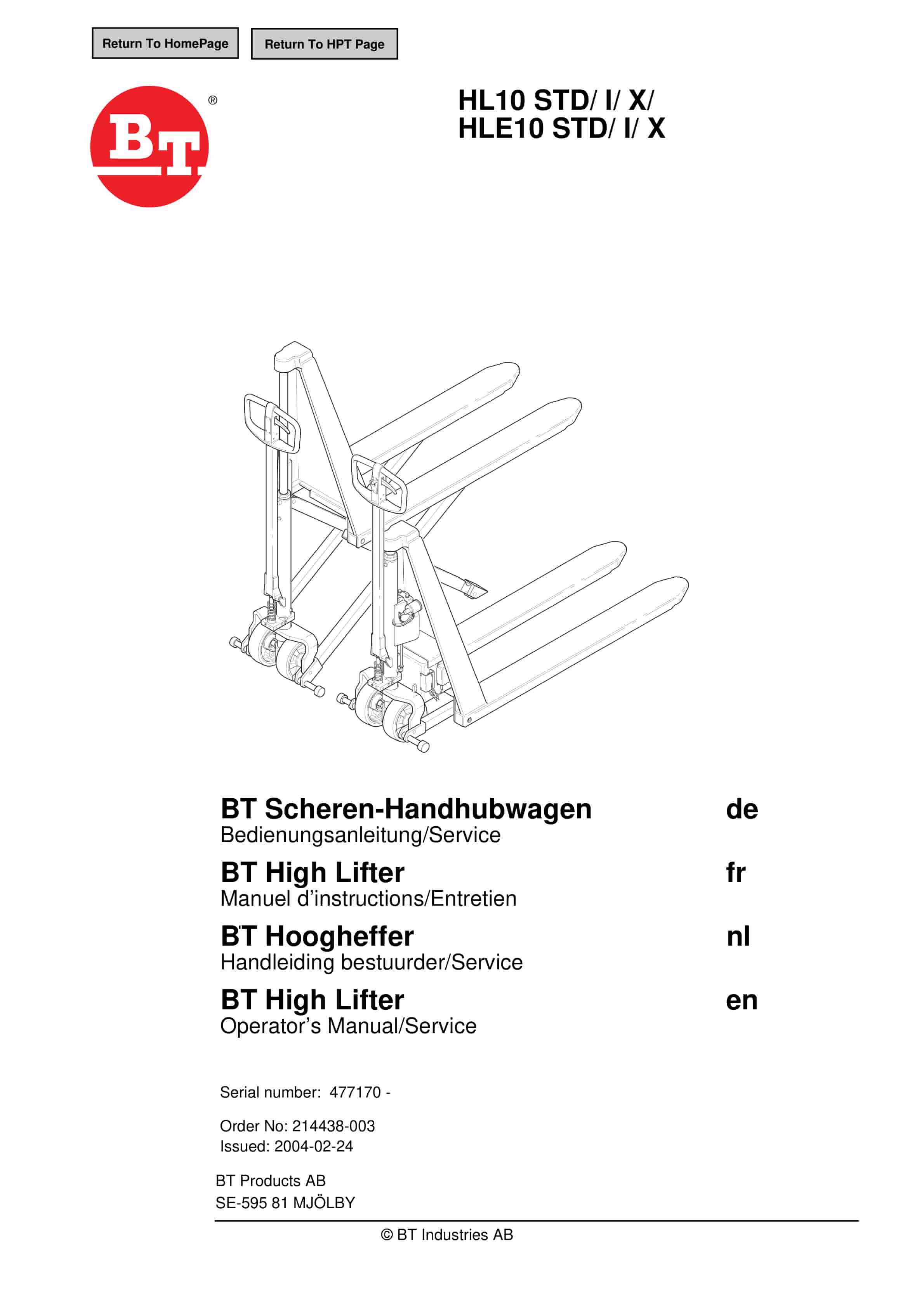
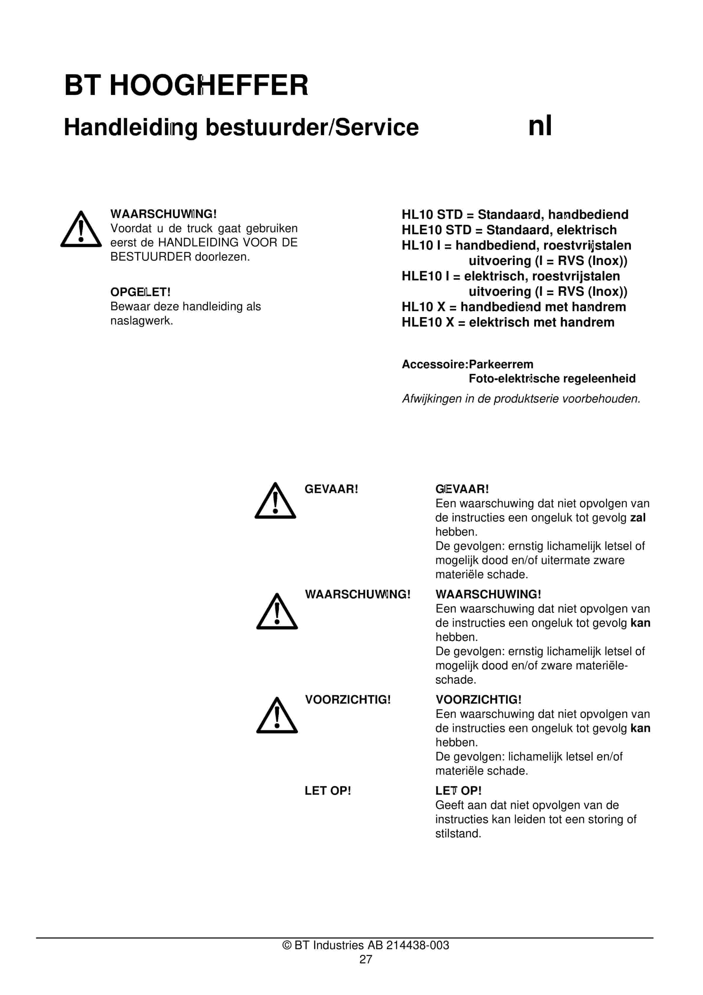
BT HL10 STD, HL10 I, HL10 X, HLE10 STD, HLE10 I, HLE10 X Operator And Service Manual 214438-003
$30.00
BT Service Manual PDF
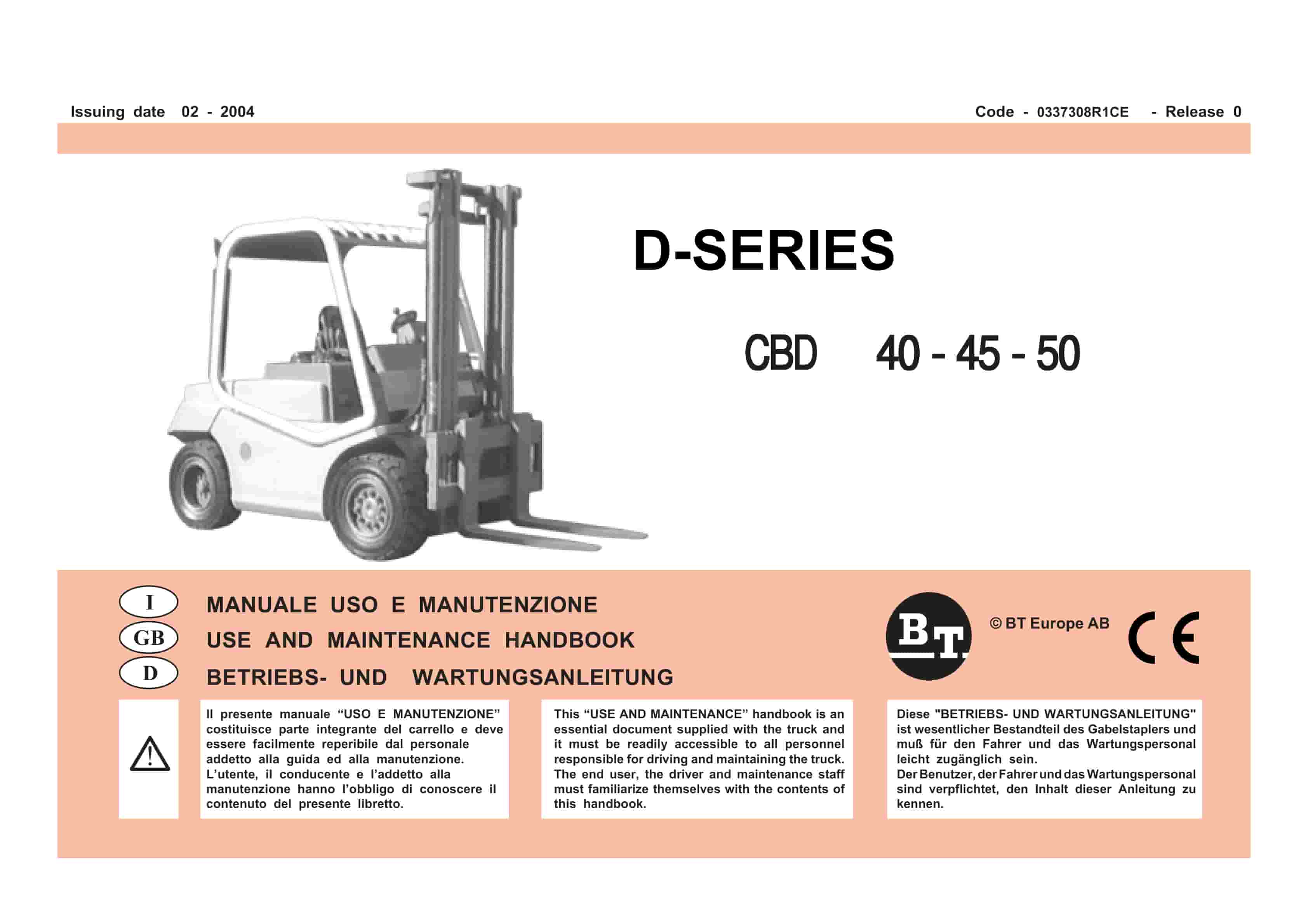
BT D-Series CBD40, CBD45, CBD50 Use And Maintenance Handbook 0337308R1CE
$30.00
BT Service Manual PDF
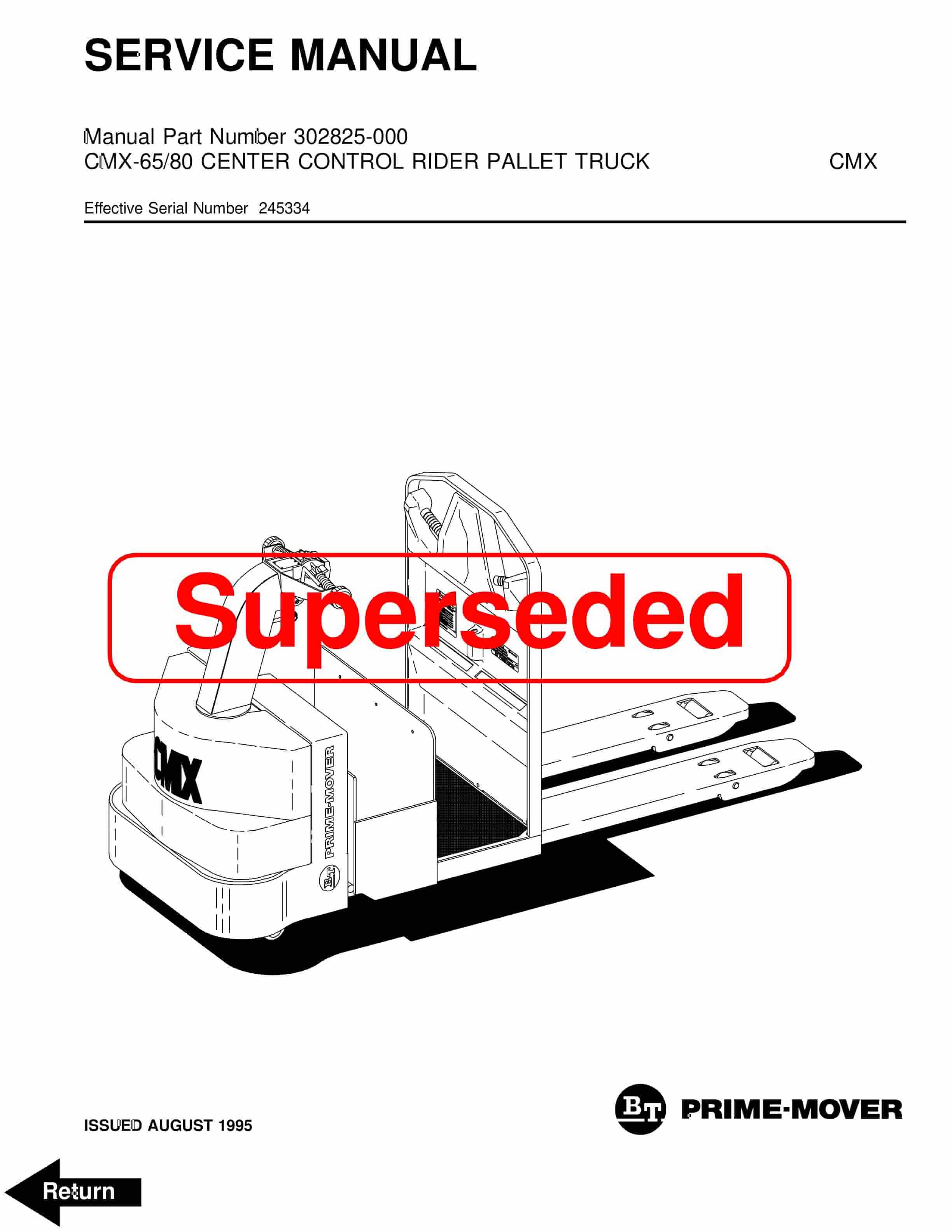
BT CMX-65, CMX-80 Center Control Riding Pallet Truck Service Manual 302825-000
$30.00