

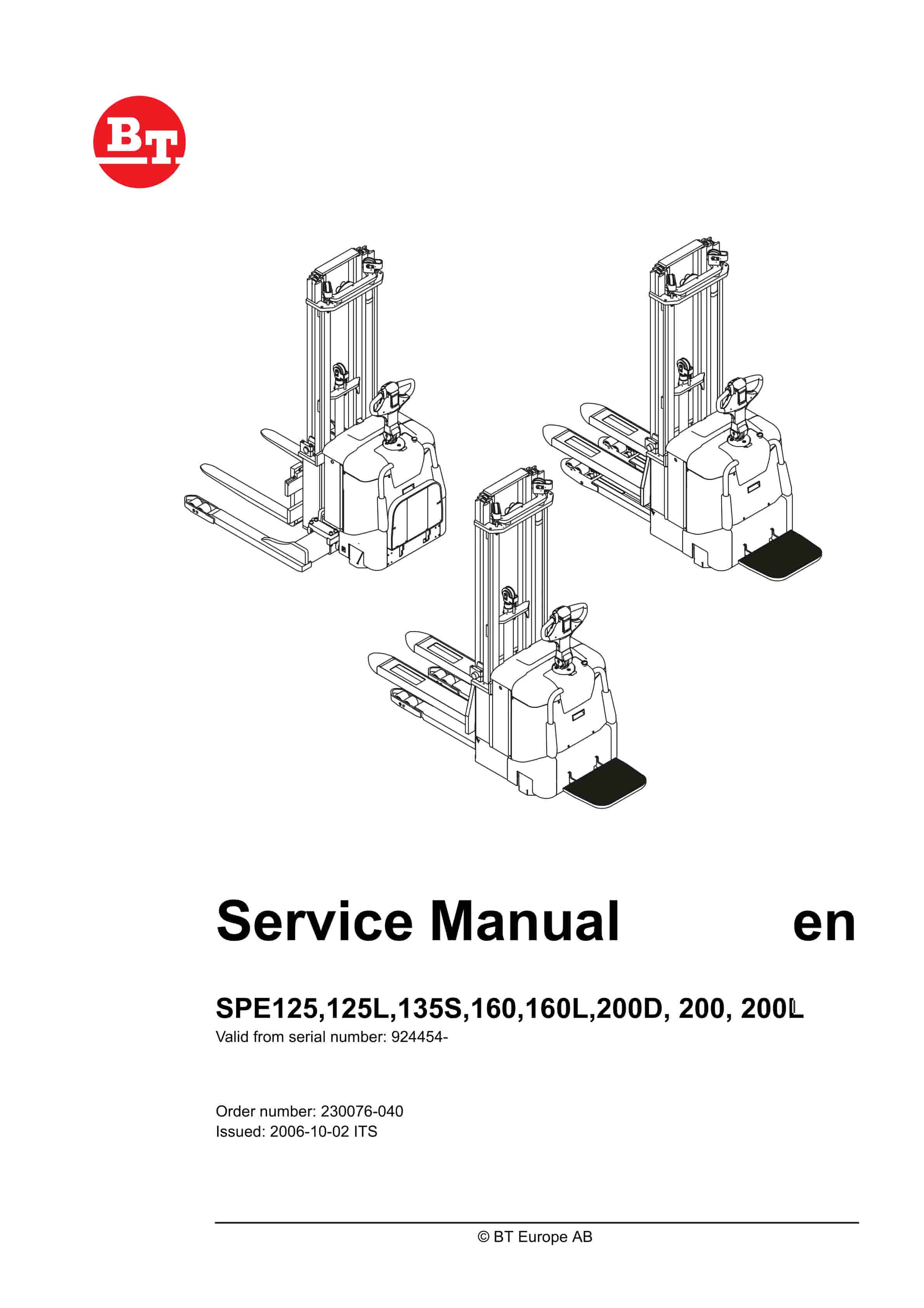
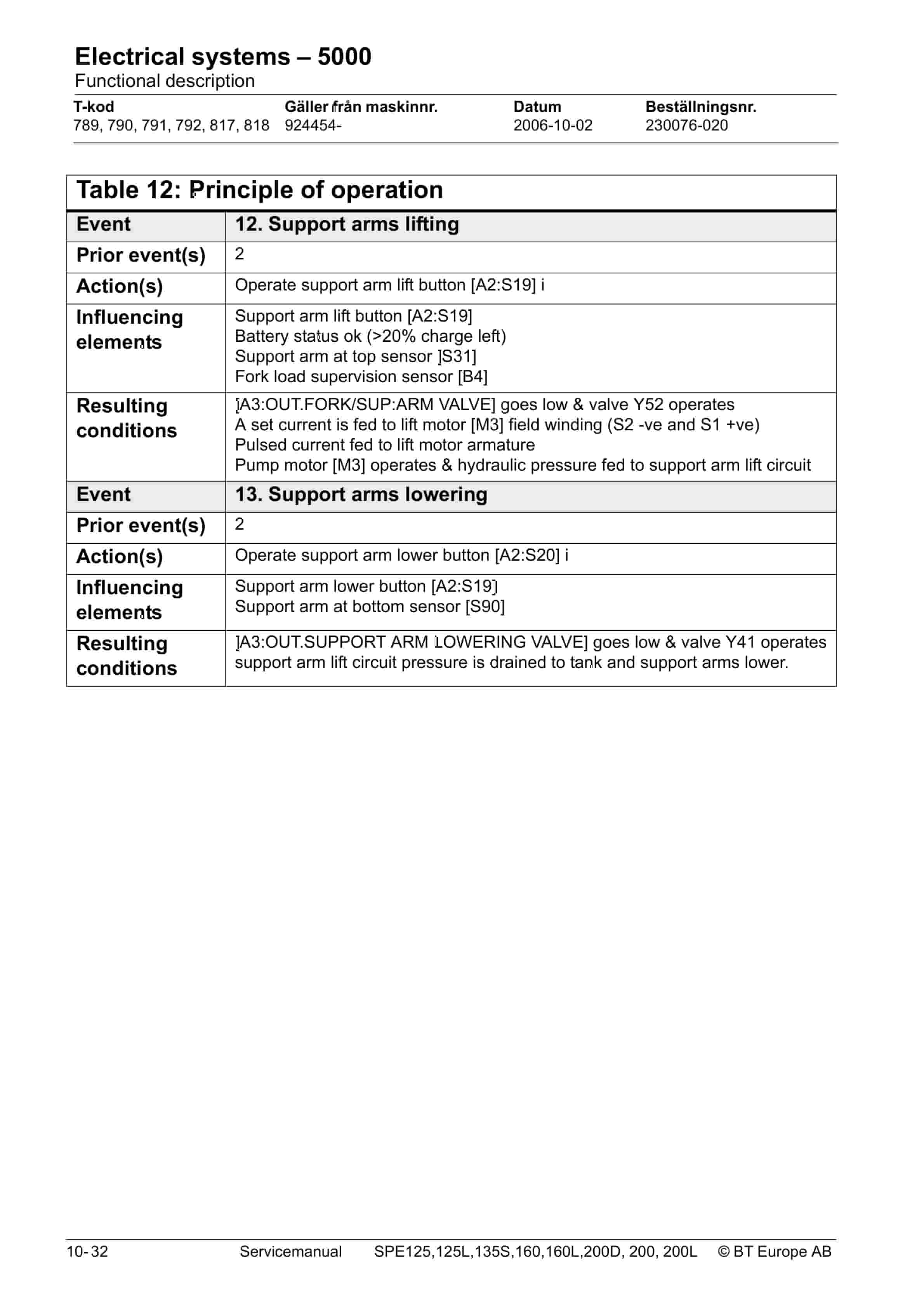
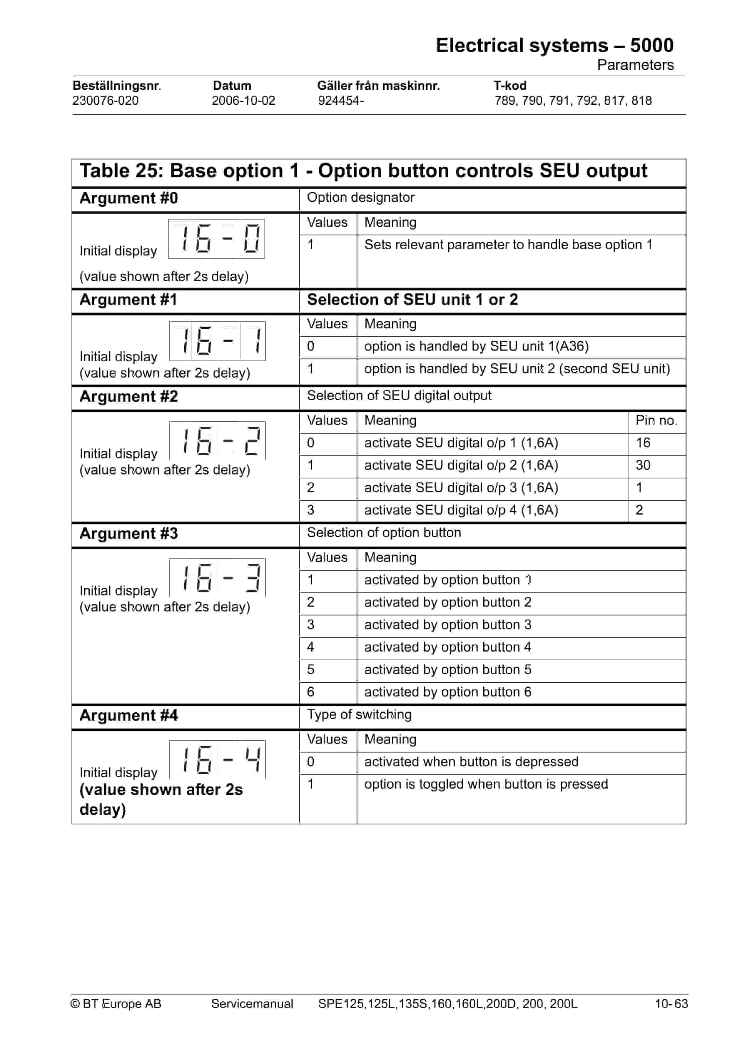
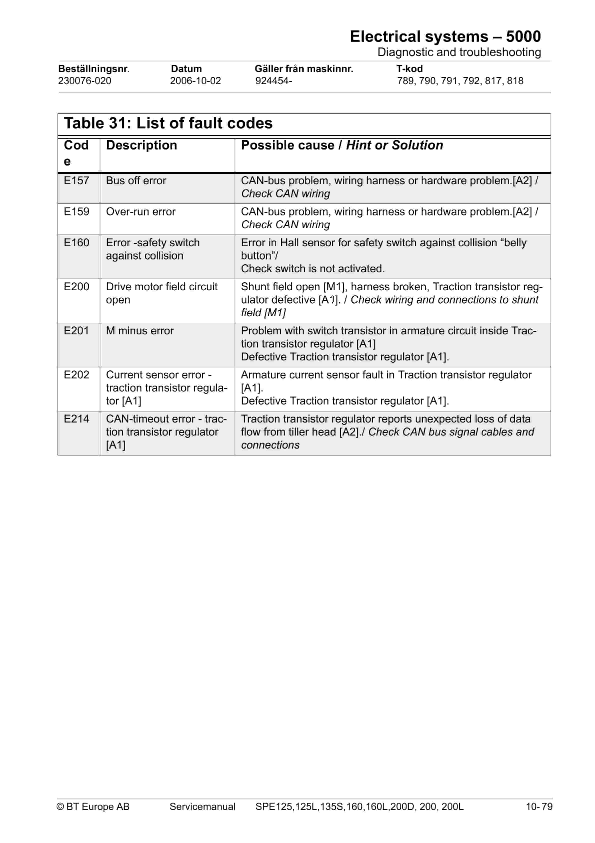
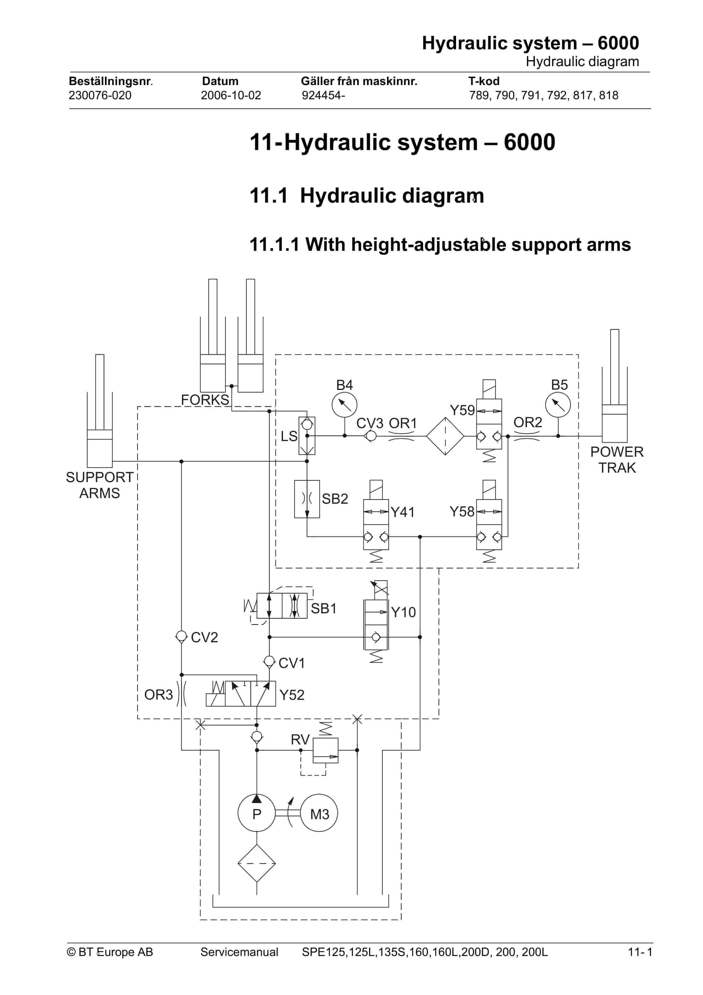
BT SPE125, SPE125L, SPE135S, SPE160, SPE160L, SPE200D, SPE200, SPE200L Service Manual 230076-040
$30.00
- Type Of Manual: Service Manual
- Manual ID: 230076-040
- : Service Manual PDF
- Number of Pages: 190
- Size: 7.8MB
- Format: PDF
Product details
-
Model List:
- SPE125, SPE125L, SPE135S, SPE160, SPE160L, SPE200D, SPE200, SPE200L
- 1. Technical data
- 1.1. General tightening torques
- 2. Maintenance
- 2.1. Safety rules during maintenance work
- 2.2. Cleaning and washing
- 2.2.1. External cleaning
- 2.2.2. Cleaning the motor compartment
- 2.2.3. Electric components
- 2.3. Safe lifting
- 2.4. Lifting the truck
- 2.5. Maintenance schedule
- 2.6. Lubrication chart
- 2.7. Oil and grease specification
- 3. Tools
- 3.1. Super Seal connectors
- 3.2. AMP connectors
- 3.2.1. AMP Connectors, 040 series
- 3.3. Molex connectors
- 3.4. Grease guns
- 3.5. Other tools
- 4. Chassis – 0000
- 4.1. Support arms
- 4.1.1. General
- 4.1.2. Main components
- 4.1.3. Maintenance
- 4.1.4. Adjusting the support arm width
- 4.1.5. Support arm replacement
- 4.2. Engine suspension
- 4.2.1. Components
- 4.2.2. Disassembly
- 4.2.3. Spring replacement
- 4.3. Platform
- 4.3.1. Components
- 4.3.2. Disassembly
- 5. Electric drive motor – 1760
- 5.1. Included components
- 5.2. Disassembly/assembly of the truck motor
- 5.2.1. Disassembly
- 5.2.2. Assembly
- 5.3. Service/repairs
- 5.3.1. Disassembly of the motor
- 5.3.2. Motor installation
- 5.3.3. Cleaning
- 6. Drive unit/gear – 2550
- 6.1. Included components
- 6.2. Leakage from top cover
- 6.3. Replacing the drive axle jointing ring
- 6.3.1. Disassembly
- 6.3.2. Assembly
- 7. Electromagnetic brake – 3370
- 7.1. Main components of the brake
- 7.2. Maintenance
- 7.2.1. Basic adjustment of the play
- 7.2.2. Brake disc replacement
- 8. Support/Castor Wheels – 3540
- 8.1. Tightening torque
- 9. Electrical steering system – 4300
- 9.1. Electrical steering servo
- 9.1.1. General
- 9.2. Steering servo components
- 9.3. Adjustment
- 9.3.1. Reference sensor
- 9.3.2. Calibration
- 9.3.2.1. Parameter 36
- 9.3.2.2. Parameter 37
- 10. Electrical systems – 5000
- 10.1. General
- 10.1.1. Part numbers
- 10.1.2. Nomenclature
- 10.2. Electrical equipment overview
- 10.2.1. Component placement
- 10.2.2. Component list
- 10.3. Electrical wiring diagram
- 10.3.1. Symbol list
- 10.3.2. Overview
- 10.3.3. Detailed wiring diagram
- 10.4. Functional description
- 10.4.1. Principle of operation
- 10.4.2. Description of steering system
- 10.4.3. Spider expansion unit (SEU)
- 10.4.4. Speed limitation
- 10.4.5. Hour meter and battery condition
- 10.4.6. TLS – Truck log system (optional)
- 10.4.6.1. General
- 10.4.6.2. Registration
- 10.4.6.3. Logging in/out SD16
- 10.4.6.4. Logging in/out S16
- 10.4.6.5. Collision sensor
- 10.4.6.6. Settings
- 10.4.7. ID unit (optional)
- 10.4.8. Cooling fan (SPE200D)
- 10.4.9. Insert (SPE200D)
- 10.5. Parameters
- 10.5.1. General
- 10.5.2. Viewing parameters -CAN key not connected
- 10.5.3. Viewing parameters – CAN key connected
- 10.5.4. Setting Driver parameters
- 10.5.5. Setting Service parameters
- 10.5.6. Summary of driver parameters
- 10.5.7. Description of driver parameters
- 10.5.7.1. 2 – Maximum speed, high range
- 10.5.7.2. 3 – Maximum acceleration
- 10.5.7.3. 4 – Neutral braking effect
- 10.5.7.4. 6 – Maximum speed, low range
- 10.5.7.5. 7 – Maximum speed, Turtle mode
- 10.5.8. Summary of service parameters
- 10.5.9. Description of service parameters
- 10.5.9.1. 10 – PIN code
- 10.5.9.2. To enter a new PIN-code
- 10.5.9.3. To remove an existing PIN-code
- 10.5.9.4. 14 – Creep speed
- 10.5.9.5. 15 – Non-configurable options
- 10.5.9.6. Setting Non-configurable options
- 10.5.9.7. 16 – Configurable option 1
- 10.5.9.8. 17 – Configurable option 2
- 10.5.9.9. 18 – Configurable option 3
- 10.5.9.10. 19 – Configurable option 4
- 10.5.9.11. 20 – Hour meter selection
- 10.5.9.12. 21 – Battery size
- 10.5.9.13. 22 – Maximum fork lowering speed
- 10.5.9.14. 23 – Fork lower stop ramp
- 10.5.9.15. 25 – Service interval
- 10.5.9.16. 35 – Log off
- 10.5.9.17. 36 – Calibrate
- 10.5.9.18. 37 – Steering offset
- 10.5.9.19. 38 – Steer servo activated
- 10.5.9.20. 39 – Log-in method operator parameter access
- 10.5.9.21. Extended keypad – General
- 10.5.9.22. Extended keypad – Programming
- 10.5.10. Configurable Option Parameters
- 10.5.10.1. General
- 10.5.10.2. Parameter 16 to 19 Configurable options
- 10.6. Diagnostic and troubleshooting
- 10.6.1. General
- 10.6.2. Fault code history
- 10.6.3. List of fault codes
- 10.6.4. Transistor regulator
- 10.6.4.1. General
- 10.6.4.2. Transistor regulator errors
- 10.6.4.3. Resetting errors
- 10.6.5. Built-in Test Function
- 10.6.5.1. Digital inputs/outputs test mode
- 10.6.6. Display test mode
- 10.7. Technical specifications – Curtis 1243
- 11. Hydraulic system – 6000
- 11.1. Hydraulic diagram
- 11.1.1. With height-adjustable support arms
- 11.1.2. Without height-adjustable support arms
- 11.2. Main Components
- 11.3. Description
- 11.3.1. Lifting system
- 11.3.2. The PowerTrak system
- 11.3.3. Working pressure
- 11.3.4. Overflow valve
- 11.3.5. Pressure sensor
- 12. Lift mast – 7000
- 12.1. Mast incline
- 12.2. Main lift chain system
- 12.2.1. Checking the chain setting
- 12.2.2. Chain inspection
- 12.2.2.1. Surface rust
- 12.2.2.2. Rusty links
- 12.2.2.3. Stiff links
- 12.2.2.4. Bolt rotation
- 12.2.2.5. Loose bolts
- 12.2.2.6. Outline wear
- 12.2.2.7. Stretching
- 12.2.2.8. Damaged discs
- 12.2.2.9. Damaged bolts
- 12.2.2.10. Dirty chain
- 12.2.3. Cleaning
- 12.2.4. Lubrication
- 13. Destruction instructions
- 13.1. General
- 13.2. Procedure
- 13.3. Abbreviations
- 13.4. Sorting
- 13.5. Chassis (0300)
- 13.5.1. Dismantling
- 13.5.2. Material handling
- 13.6. Hoods, covers (0340)
- 13.6.1. Dismantling
- 13.6.2. Material handling
- 13.7. Fork structure (low-lifter) (0380)
- 13.7.1. Dismantling
- 13.7.2. Material handling
- 13.8. Travel platform including mount (0560)
- 13.8.1. Dismantling
- 13.8.2. Material handling
- 13.9. Overhead guard (option) (0810)
- 13.9.1. Dismantling
- 13.9.2. Material handling
- 13.10. Operator protective device (0840)
- 13.10.1. Dismantling
- 13.10.2. Material handling
- 13.11. Electric pump motor (1710)
- 13.11.1. Dismantling
- 13.11.2. Material handling
- 13.12. Electric travel drive motor (1760)
- 13.12.1. Dismantling
- 13.12.2. Material handling
- 13.13. Drive unit/gear (2550)
- 13.13.1. Dismantling
- 13.13.2. Material handling
- 13.14. Wheels (3500)
- 13.14.1. Dismantling
- 13.14.2. Material handling
- 13.15. Steering arm (4110)
- 13.15.1. Dismantling
- 13.15.2. Material handling
- 13.16. Steering arm (4110)
- 13.16.1. Dismantling
- 13.16.2. Material handling
- 13.17. General electric equipment (5100)
- 13.17.1. Dismantling
- 13.17.2. Material handling
- 13.18. Cabling (5590)
- 13.18.1. Dismantling
- 13.18.2. Material handling
- 13.19. Steering and protective electronics (5700)
- 13.19.1. Dismantling
- 13.19.2. Material handling
- 13.20. Lift/lowering sensor (5820) and safety sensor (5830)
- 13.20.1. Dismantling
- 13.20.2. Material handling
- 13.21. Hydraulic unit (6100)
- 13.21.1. Dismantling
- 13.21.2. Material handling
- 13.22. Main mast (7100)
- 13.22.1. Dismantling
- 13.22.2. Material handling
- 13.23. Chassis-mounted hydraulic oil lines (6230) (and main lift cylinder (6610))
- 13.23.1. Dismantling
- 13.23.2. Material handling
- 13.24. Battery charger connector (9380)
- 13.24.1. Dismantling
- 13.24.2. Material handling
Related products
-
BT C3E150 to C4E200 Repair Manual 036-0434-00
$30.00 Add to cart -
BT CBE 12T to CBE 20F Service Manual 036-0410-06
$30.00 Add to cart -
BT CBE 25, CBE 30, CBE 30L, CBE 35 Service Manual 036-0409-02
$30.00 Add to cart -
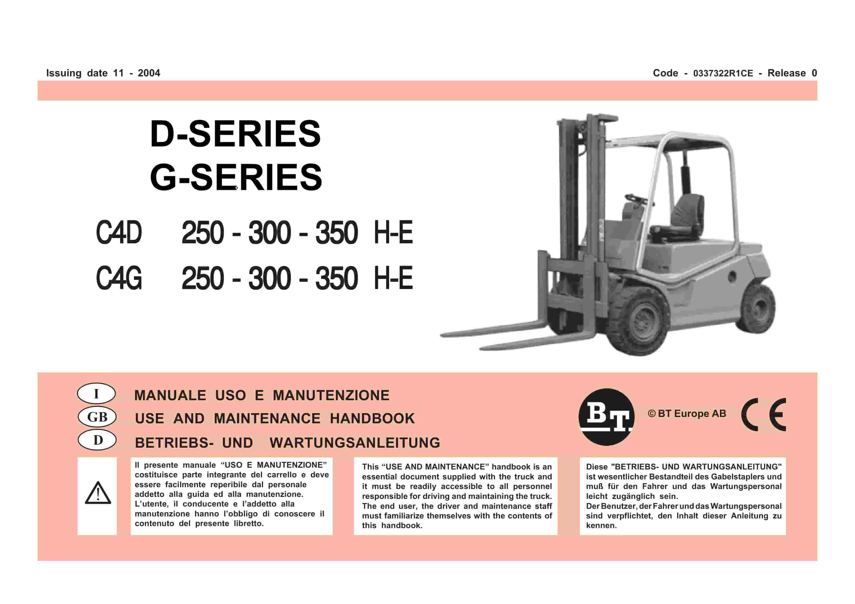
BT D-G-Series C4D250H-E, C4D300H-E, C4D350H-E, C4G250H-E, C4G300H-E, C4G350H-E Use And Maintenance Handbook 0337322R1CE
$30.00 Add to cart -
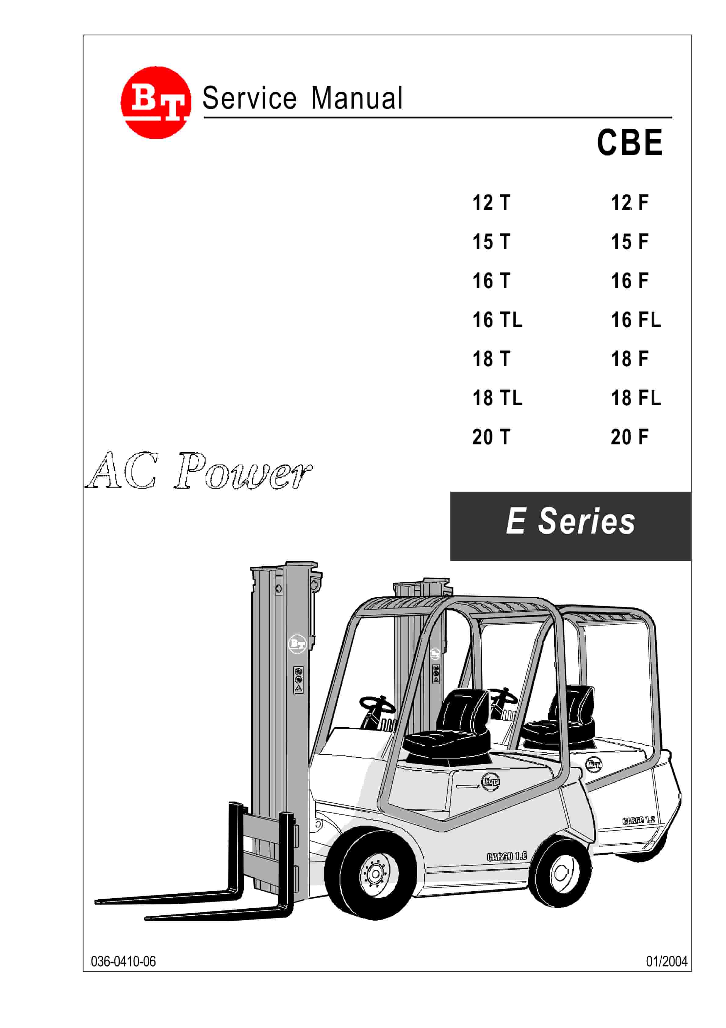
BT CBE 12T to CBE 20F Service Manual 036-0410-03
$30.00 Add to cart


