

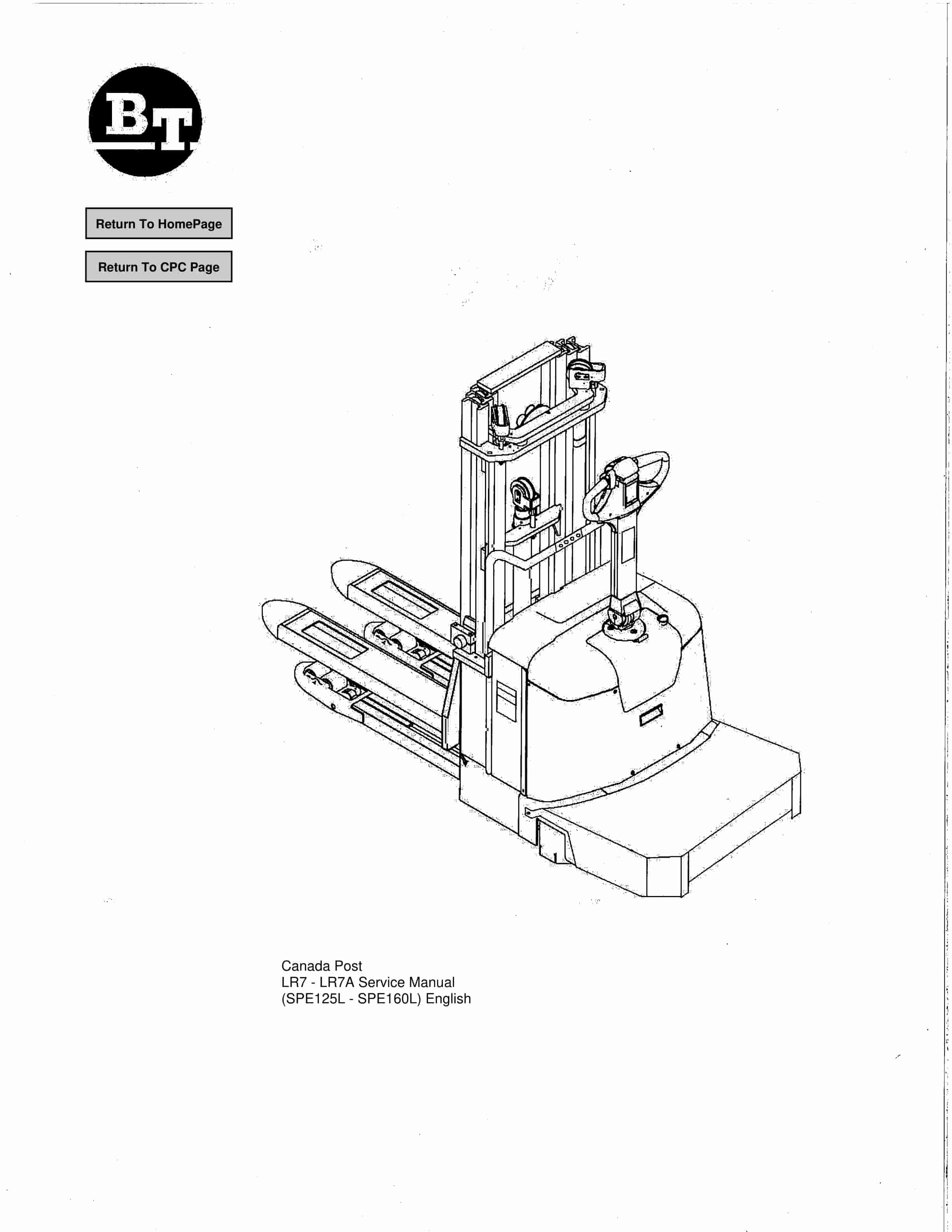
BT SPE125, SPE125L, SPE160, SPE160L Service Manual 218367-040
$30.00
- Type Of Manual: Service Manual
- Manual ID: 218367-040
- : Service Manual PDF
- Number of Pages: 173
- Size: 17.9MB
- Format: PDF
Product details
-
Model List:
- SPE125, SPE125L, SPE160, SPE160L
- 1. Return To HomePage
- 2. Table of Contents
- 3. Presentation of the truck – M2
- 3.1. Intended application of the truck
- 3.2. Forbidden application of the truck
- 3.3. Truck data
- 3.4. Truck dimensions
- 3.5. Identification plate
- 3.6. Capacity plate
- 3.7. Addition and information plate
- 3.8. Capacity plate for double pallet handling
- 3.9. Main components
- 3.10. Warning and information plates
- 4. Technical data – M4
- 4.1. General tightening torques
- 5. Installation and maintenance instructions – P1
- 5.1. Truck installation
- 5.1.1. Lifting the truck
- 5.1.2. Battery installation
- 5.1.3. Putting into service
- 5.2. Introduction, maintenance
- 5.2.1. Safety rules during maintenance work
- 5.3. Cleaning and washing
- 5.3.1. External cleaning
- 5.3.2. Cleaning the motor compartment
- 5.3.3. Electric components
- 5.4. Safe lifting
- 6. Maintenance schedule – P2
- 6.1. Lubrication chart
- 7. Oil and grease specification – P3
- 8. Tools – P4
- 8.1. Super Seal connectors
- 8.2. AMP connectors
- 8.2.1. AMP Connectors, 040 series
- 8.3. Molex connectors
- 8.4. Other tools
- 9. Electric drive motor – 1760
- 9.1. Included components
- 9.2. Disassembly/assembly of the truck motor
- 9.2.1. Disassembly
- 9.2.2. Assembly
- 9.3. Service/repairs
- 9.3.1. Disassembly of the motor
- 9.3.2. Motor installation
- 9.3.3. Cleaning
- 9.4. Technical data
- 10. Drive unit/gear – 2550
- 10.1. Included components
- 10.1.1. Technical data
- 10.2. Leakage from top cover
- 10.3. Replacing the drive axle jointing ring
- 10.3.1. Disassembly
- 10.3.2. Assembly
- 11. Electromagnetic brake – 3370
- 11.1. Main components of the brake
- 11.2. Maintenance
- 11.2.1. Basic adjustment of the play
- 11.2.2. Brake disc replacement
- 12. Electrical systems – 5000
- 12.1. Electrical equipment overview
- 12.2. Equipment list and electrical diagram
- 12.2.1. Electrical wiring diagram 1 of 8
- 12.2.2. Electrical wiring diagram 2 of 8
- 12.2.3. Electrical wiring diagram 3 of 8
- 12.2.4. Electrical wiring diagram 4 of 8
- 12.2.5. Electrical wiring diagram 5 of 8
- 12.2.6. Electrical wiring diagram 6 of 8
- 12.2.7. Electrical wiring diagram 7 of 8
- 12.2.8. Electrical Diagrams LR7(SPE160L)
- 12.3. Functional description
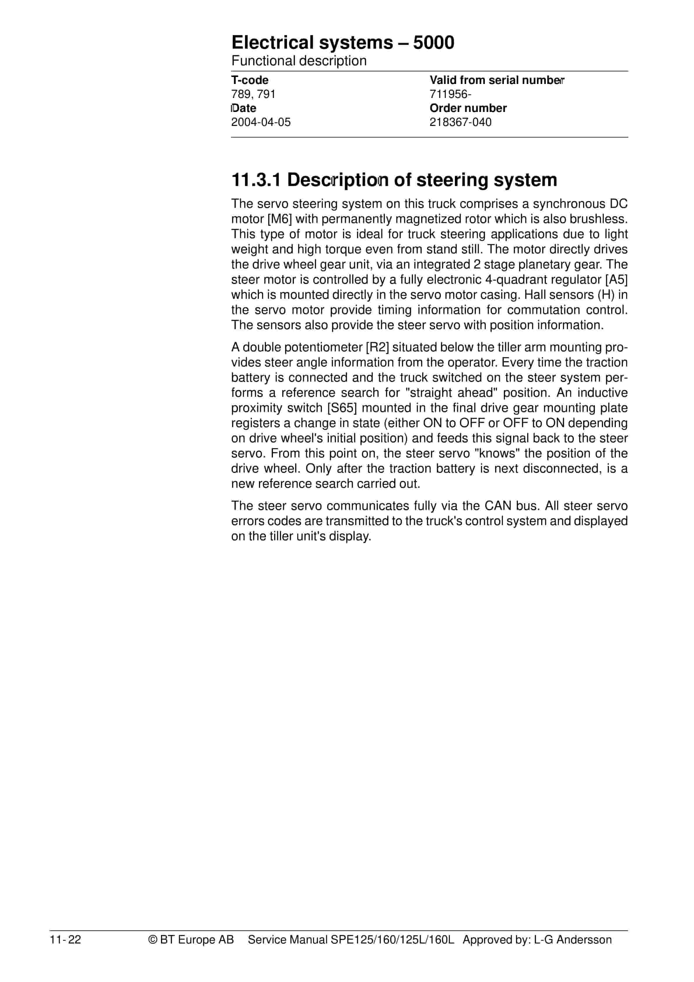
- 12.3.1. Description of steering system
- 12.4. Speed limitation
- 12.5. Hour meter and battery condition
- 12.6. Diagnostic and troubleshooting
- 12.6.1. Fault codes
- 12.6.2. Fault code history
- 12.6.3. List of fault codes
- 12.6.4. Transistor regulator troubleshooting and error codes
- 12.6.5. Built-in Test Function
- 12.6.6. Display test mode
- 12.7. Part numbers
- 12.8. Parameters
- 12.8.1. General
- 12.8.2. Viewing parameters -CAN key not connected
- 12.8.3. Viewing parameters -CAN key connected
- 12.8.4. Setting Driver parameters
- 12.8.5. Setting Service parameters
- 12.8.6. Summary of driver parameters
- 12.8.7. Description of driver parameters
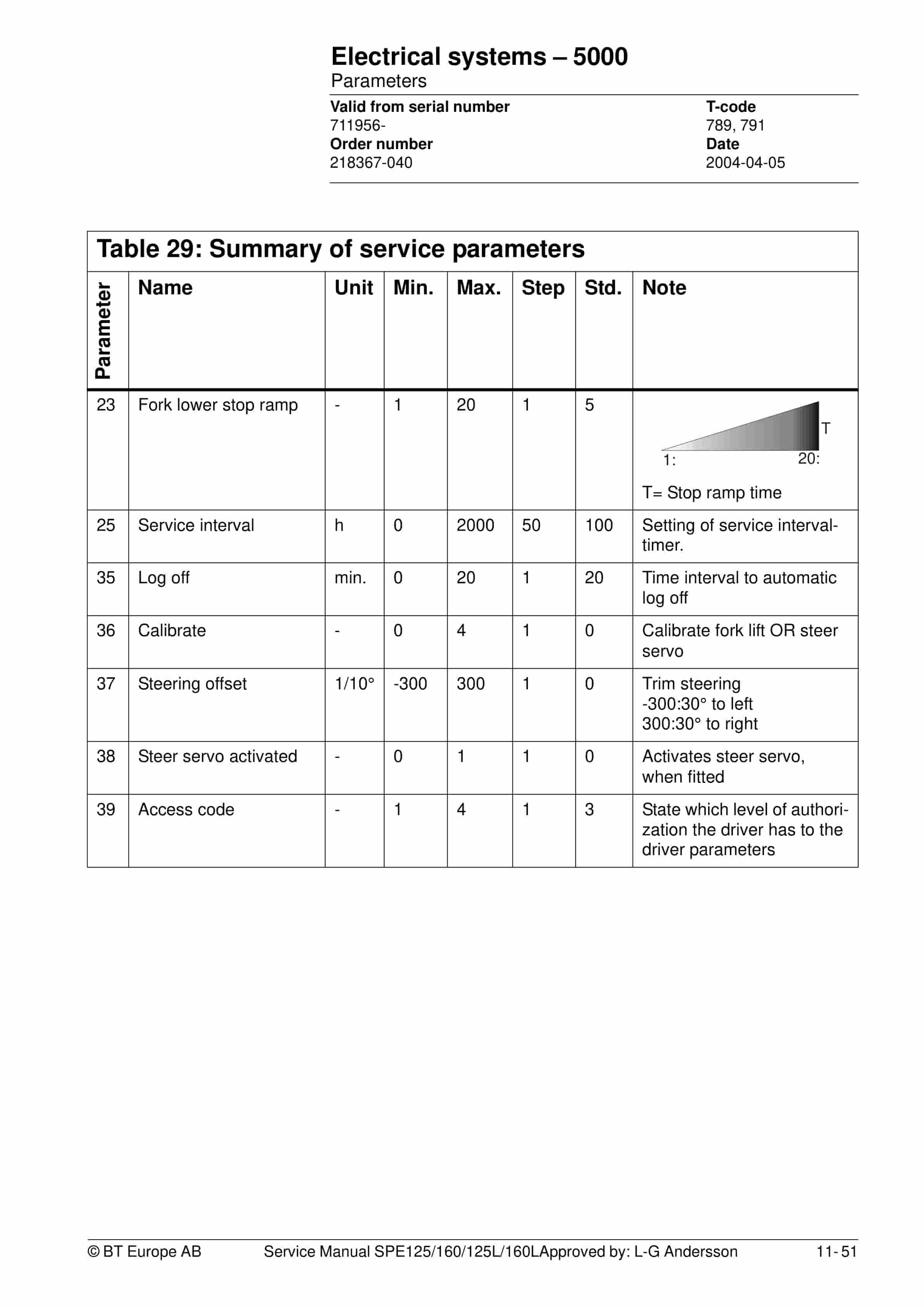
- 12.8.8. Summary of service parameters
- 12.8.9. Description of service parameters
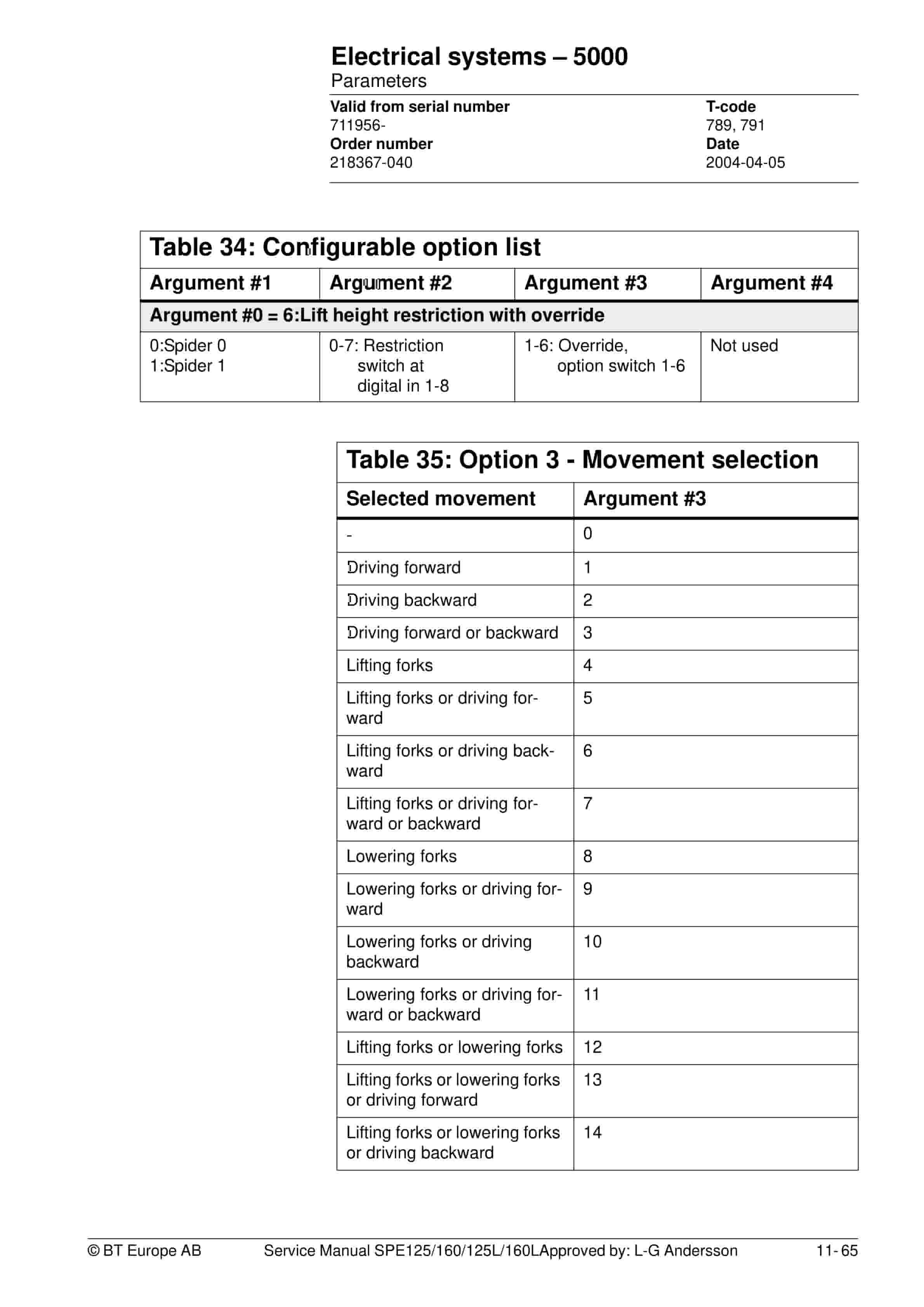
- 12.8.10. Option Parameters
- 12.9. Technical specifications – Curtis 1243
- 13. Hydraulic system – 6000
- 13.1. Hydraulic diagram
- 13.1.1. SPE125L/160L
- 13.1.2. SPE125/160
- 13.1.3. Main components
- 13.1.4. Description
- 14. Main lift chain system – 7120
- 14.1. General
- 14.2. Checking the chain setting
- 14.3. Chain inspection
- 14.3.1. Noise
- 14.3.2. Surface rust
- 14.3.3. Rusty links
- 14.3.4. Stiff links
- 14.3.5. Bolt rotation
- 14.3.6. Loose bolts
- 14.3.7. Outline wear
- 14.3.8. Stretching
- 14.3.9. Damage
- 14.3.10. Damaged discs
- 14.3.11. Damaged bolts
- 14.3.12. Dirty chain
- 14.4. Cleaning
- 14.5. Lubrication
- 15. Control/computer equipment – 8700
- 15.1. General
- 15.2. Connection
- 15.3. Layout
- 15.3.1. Main program screen
- 15.3.2. Nodes
- 15.3.3. Icons
- 15.3.4. Tool buttons and menu bar
- 15.3.5. Information window
- 15.3.6. Status bar
- 15.4. Connection function
- 15.5. Disconnection function
- 15.6. Downloading program function
- 15.6.1. Normal downloading (truck with key)
- 15.6.2. Normal downloading (truck with keypad)
- 15.6.3. Emergency downloading (truck with keypad)
- 15.6.4. Downloading in old versions of logic card
- 15.6.5. Emergency downloading (truck with keypad)
- 15.7. Truck report function
- 15.8. Parameters function
- 15.9. Diagnostics function
- 15.9.1. Representation of signal colours
- 15.9.2. Tiller arm tab
- 15.9.3. Drive Controller tab
- 15.9.4. EPS tab (only OL 20 / 25)
- 15.10. Other menu functions
- 15.10.1. Save to file
- 15.10.2. Download from file
- 15.10.3. Reset CAN adapter
- 15.10.4. Delete error code log
- 15.10.5. Reset hour meter
- 15.10.6. Read error code log
- 15.10.7. Adjust date and time
- 15.10.8. Adjusting the hour meter on older cards
- 15.10.9. Help
- 15.10.10. Exit
- 15.11. Specifications
- 15.12. Installation
- 15.12.1. Installation on a PC with Windows 95/98
- 15.12.2. Installation on a PC with Windows XP/2000
- 15.12.3. Installation on a PC with Windows NT
- 15.12.4. In case of communication problems with CAN
- 15.12.5. To uninstall
Related products
-
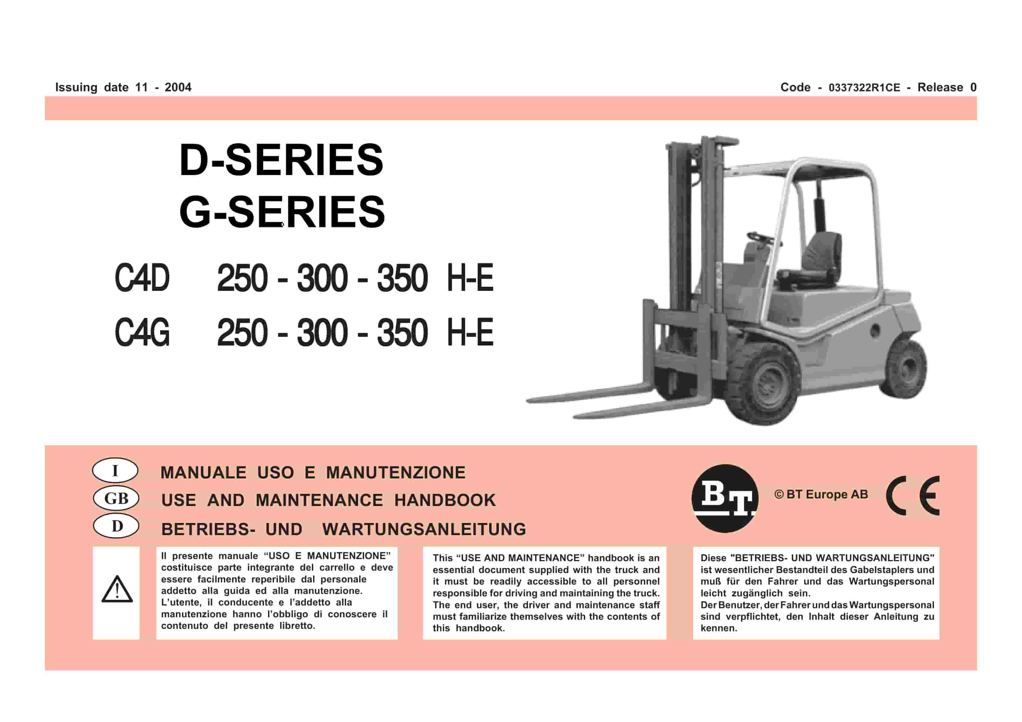
BT D-G-Series C4D250H-E, C4D300H-E, C4D350H-E, C4G250H-E, C4G300H-E, C4G350H-E Use And Maintenance Handbook 0337322R1CE
$30.00 Add to cart -
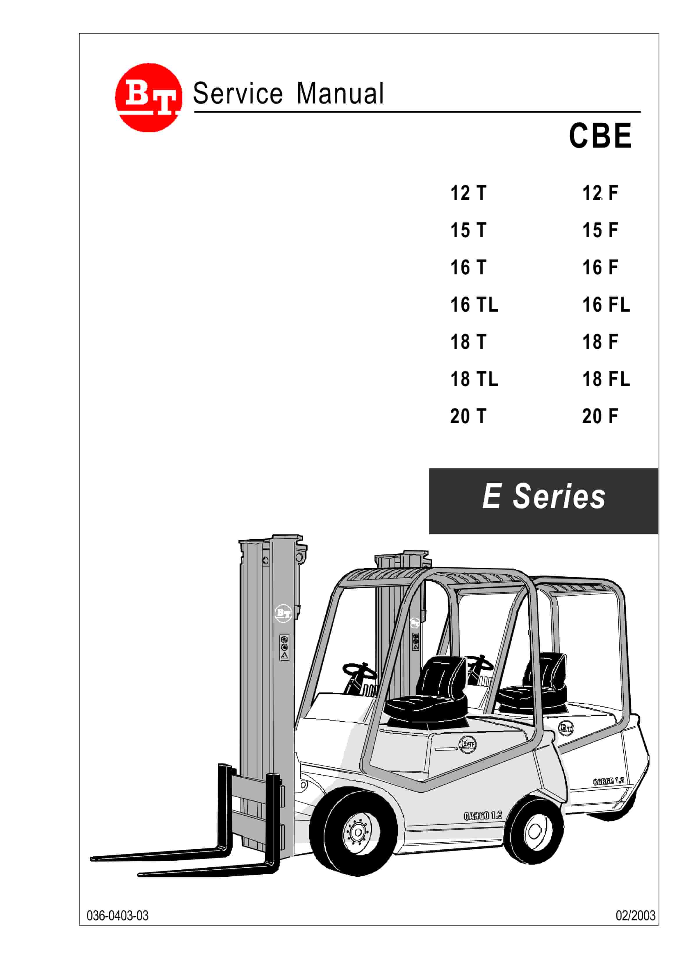
BT CBE 12T to CBE 20F Service Manual 036-0403-03
$30.00 Add to cart -
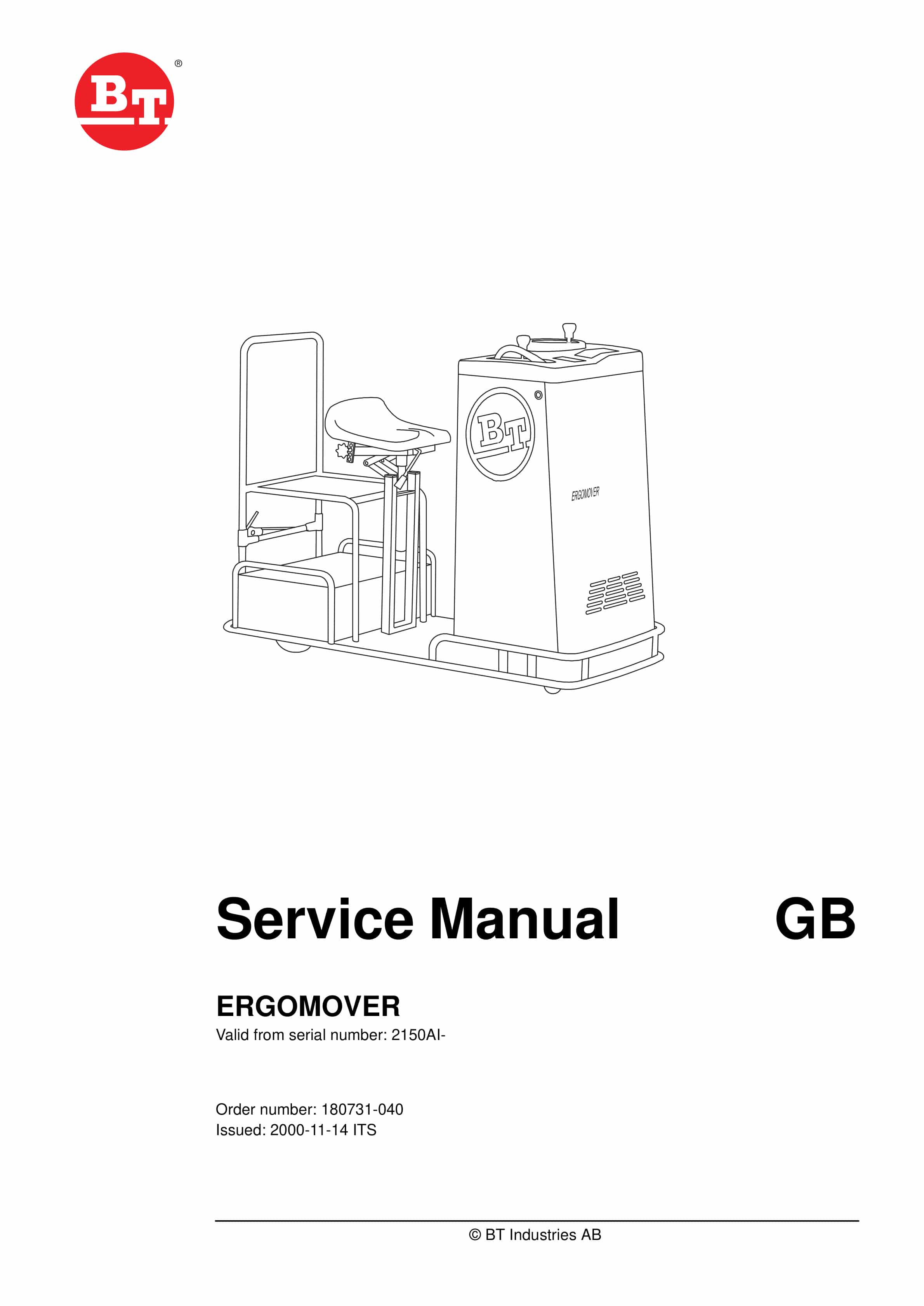
BT ERGOMOVER Service Manual 180731-040
$30.00 Add to cart -
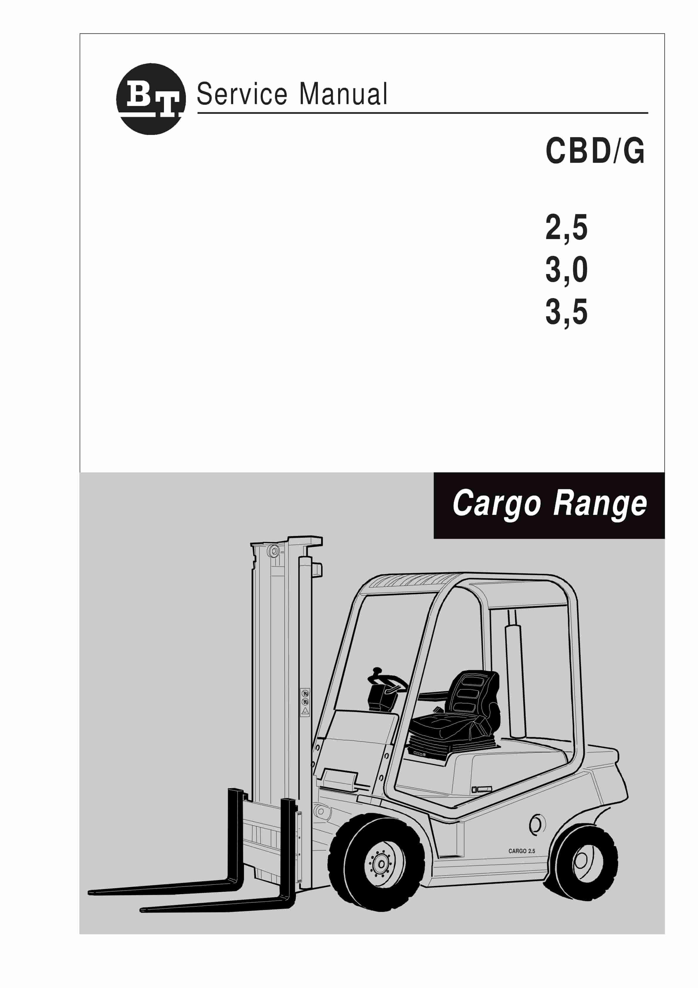
BT CBD-G 2.5, 3.0, 3.5 Service Manual 036-0405-01
$30.00 Add to cart -
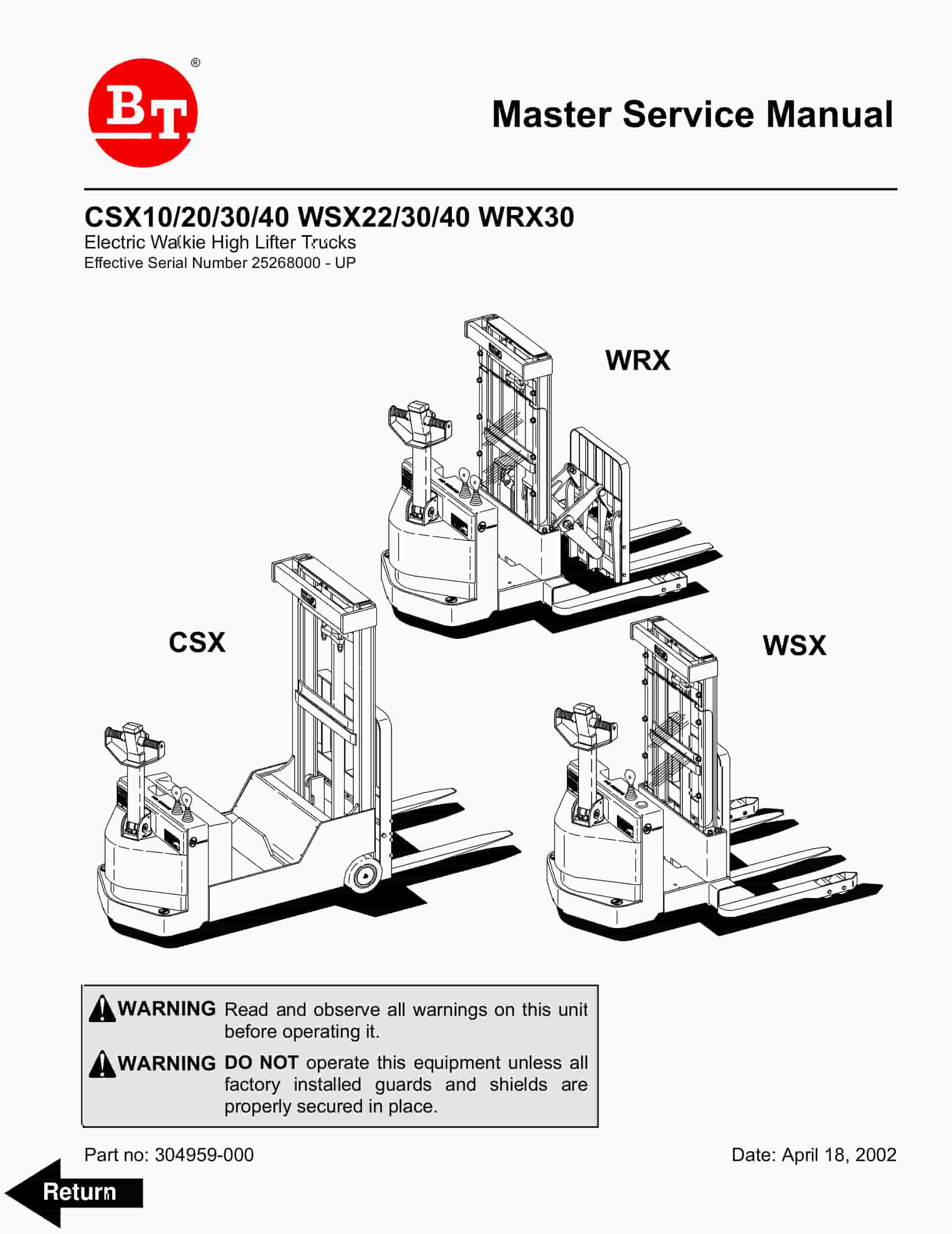
BT CSX10, CSX20, CSX30, CSX40, WSX22, WSX30, WSX40, WRX30 Electric Walkie High Lifter Truck Service Manual 304959-000
$30.00 Add to cart


