

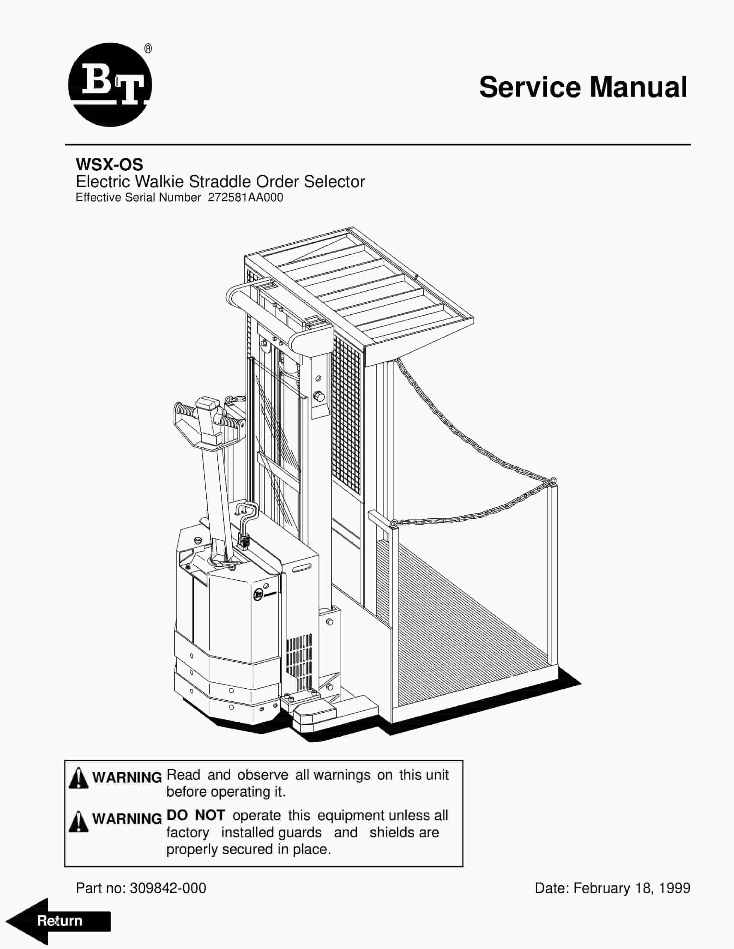
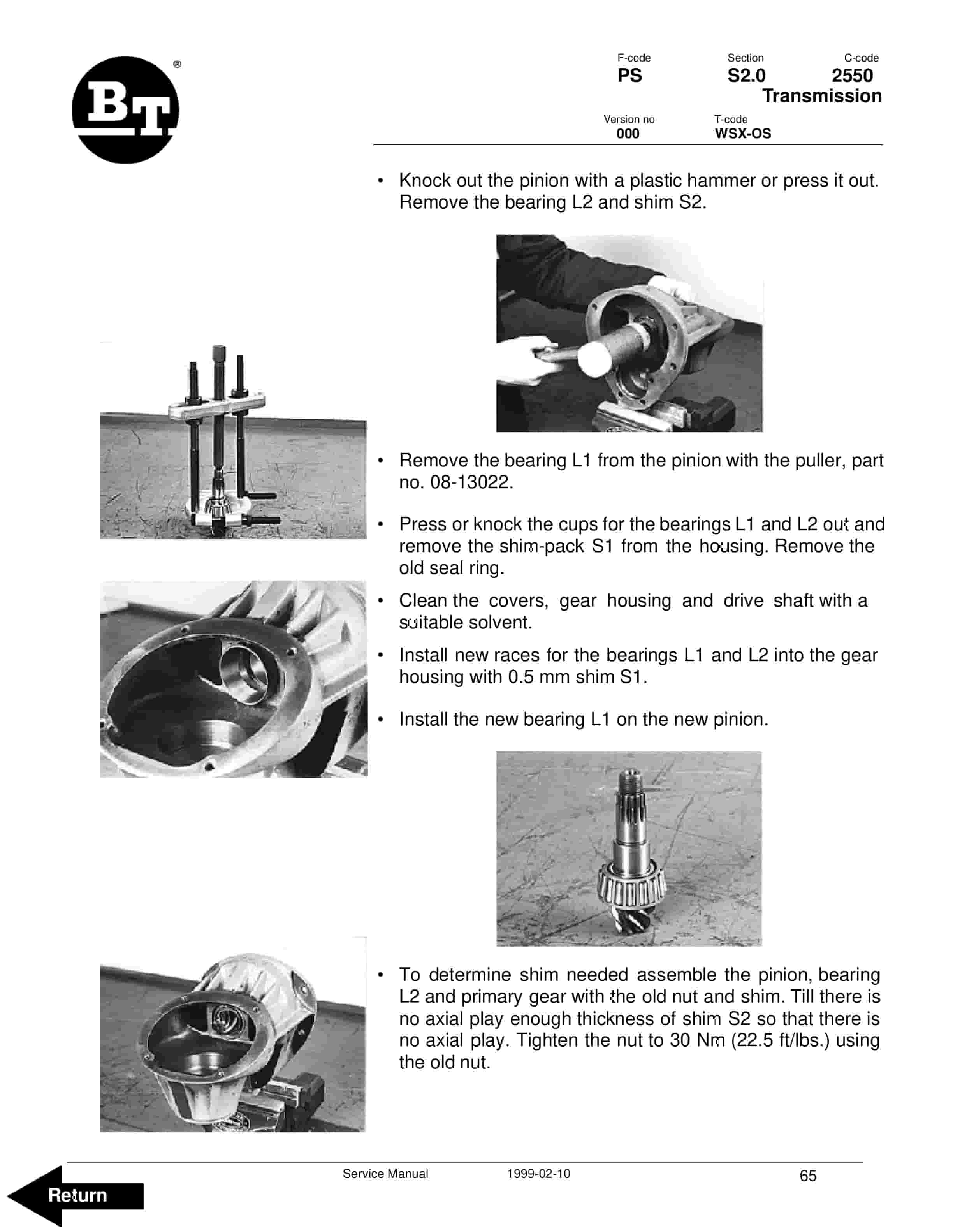
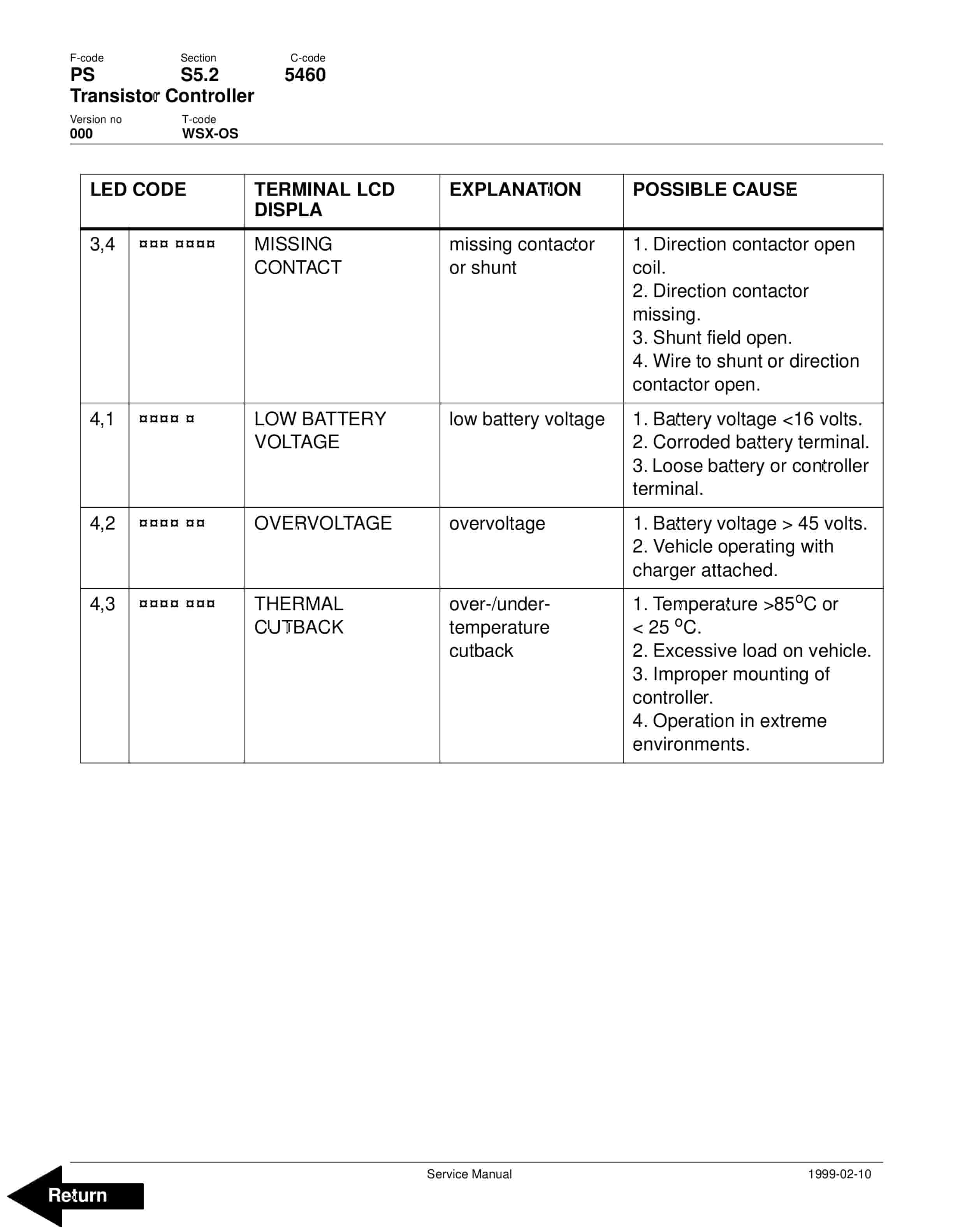
BT WSX-OS Electric Walkie Straddle Order Selector Service Manual 309842-000
$30.00
- Type Of Manual: Service Manual
- Manual ID: 309842-000
- : Service Manual PDF
- Number of Pages: 132
- Size: 2.3MB
- Format: PDF
Product details
-
Model List:
- WSX-OS Electric Walkie Straddle Order Selector
- 1. Front Cover
- 2. BT Standard Codes
- 3. Warning Symbols
- 3.1. Warning Levels
- 4. Prohibitory Symbols
- 4.1. Ordinance Symbols
- 5. Introduction, service manual
- 6. Contents, Section M
- 6.1. Machine Information
- 7. General product information
- 7.1. Presentation of the WSX-OS
- 7.1.1. Intended application of the truck
- 7.1.2. Forbidden application of the truck
- 7.1.3. Truck data
- 7.1.4. Truck dimensions
- 7.1.5. Truck data plate
- 7.2. Main components
- 7.3. Warning and information signs
- 8. Inch (SAE) and Metric Fasteners
- 8.1. Introduction
- 8.2. Nomenclature, Threads
- 8.3. Strength Identification
- 8.4. Conversion of Metric and English Units
- 9. Technical service data
- 10. Ordering Spare Parts
- 11. Contents, Section P
- 11.1. Planned Maintenance
- 12. Introduction, Maintenance
- 12.1. Safe Jacking Procedure
- 13. Service schedule
- 14. Lubrication chart
- 15. Oil and grease specification
- 15.1. Approved oils and grease
- 16. Contents, Section S
- 16.1. Service Instructions
- 17. Support arm chassis
- 17.1. General
- 17.2. Main components
- 17.3. Maintenance
- 17.4. Adjustment of the support arm width
- 17.5. Exchange of support arms
- 18. Transmission
- 18.1. General technical description
- 18.1.1. Technical data
- 18.1.2. Gear components
- 18.1.3. Special tools
- 18.2. Removing the gear from the truck
- 18.3. Change of seal on the drive shaft
- 18.4. Reconditioning of the gear
- 19. Electrical System
- 19.1. Electrical panel, components.
- 19.2. List of symbols.
- 19.2.1. Circuit diagram 1(4)
- 19.2.2. Circuit diagram 2(4)
- 19.2.3. Circuit diagram 3(4)
- 19.2.4. Circuit diagram 4(4)
- 19.3. DESCRIPTION OF FUNCTION
- 19.3.1. General
- 19.3.2. Adjustable settings
- 19.3.3. References
- 19.3.4. Key switch S17 in the ON position
- 19.3.5. The operating arm in drive position, S10, brake switch closed
- 19.3.6. Driving, platform direction
- 19.3.7. Driving, steer wheel direction
- 19.3.8. Reversing/motor brake platform direction to steer wheel direction
- 19.3.9. Reversing/motor brake steer wheel direction to platform direction
- 19.3.10. Reverser switch
- 19.3.11. Lifting the platform
- 19.3.12. Horn
- 19.4. Options
- 19.4.1. Electrical lowering of the platform
- 19.5. Wire Coupler
- 19.5.1. Electrical wire coupler
- 20. Battery Controller / Hourmeter / Lift Interrupt
- 20.1. General Information
- 20.2. Electrical
- 20.2.1. Voltage
- 20.2.1.1. The Contact Voltage and Current Ratings for Switching Resistive Loads.
- 20.2.1.2. Memory Retention
- 20.3. Battery Controller (BC)
- 20.3.1. General Information
- 20.3.1.1. Discharge Adjustment
- 20.3.2. Reset
- 20.3.3. Key Switch
- 20.3.4. Hourmeter
- 20.4. Troubleshooting
- 20.4.1. Battery Discharge Indicator (BDI)
- 20.4.1.1. No Reset
- 20.4.1.2. Reset After Break in Power
- 20.4.1.3. No Discharge, Gauge Does Not Run Down
- 20.4.1.4. No Lockout
- 20.4.1.5. No Lift
- 20.4.1.6. Early Lockout
- 20.4.1.7. LEDs Do Not Light
- 20.4.2. Hourmeter
- 20.4.2.1. No Display
- 20.4.2.2. Hourmeter Glass Icon Does Not Flash
- 20.4.2.3. Hourmeter Glass Icon Always Flashes
- 21. Transistor Controller
- 21.1. Motor circuit
- 21.2. Control circuit
- 21.3. Technical specification
- 21.4. Adjustment panel
- 21.4.1. Adjustable Potentiometers
- 21.4.2. Connection of hand held terminal
- 21.4.3. Status LED
- 21.5. Maintenance
- 21.5.1. Safety
- 21.5.2. Cleaning
- 21.6. Diagnostics and troubleshooting
- 22. PCB Card
- 22.1. The PCB
- 22.2. Connectors and adjustments
- 22.3. Terminals and LEDs
- 23. Hydraulic system, mechanical lowering
- 23.1. General
- 23.2. Description of function
- 23.2.1. Hydraulic diagram and components
- 23.2.2. Main components
- 23.2.3. Description
- 23.2.3.1. Lift
- 23.2.3.2. Lower
- 23.2.3.3. Operating pressure
- 23.2.3.4. Relief valve
- 23.2.3.5. Hydraulic pressure switch
- 24. Hydraulic system, electrical lowering
- 24.1. General
- 24.2. Description of function
- 24.2.1. Hydraulic diagram and components
- 24.2.2. Main components
- 24.2.3. Description
- 24.2.3.1. Lift
- 24.2.3.2. Lower
- 24.2.3.3. Lower, electrical
- 24.2.3.4. Operating pressure
- 24.2.3.5. Relief valve
- 24.2.3.6. Hydraulic pressure switch
- 25. Lift Cylinder
- 25.1. Cylinder Repair
- 25.1.1. Removal
- 25.1.2. Disassembly
- 25.1.3. Assembly
- 25.1.4. Installation
- 26. Key pad
- 27. Back Cover
Related products
-
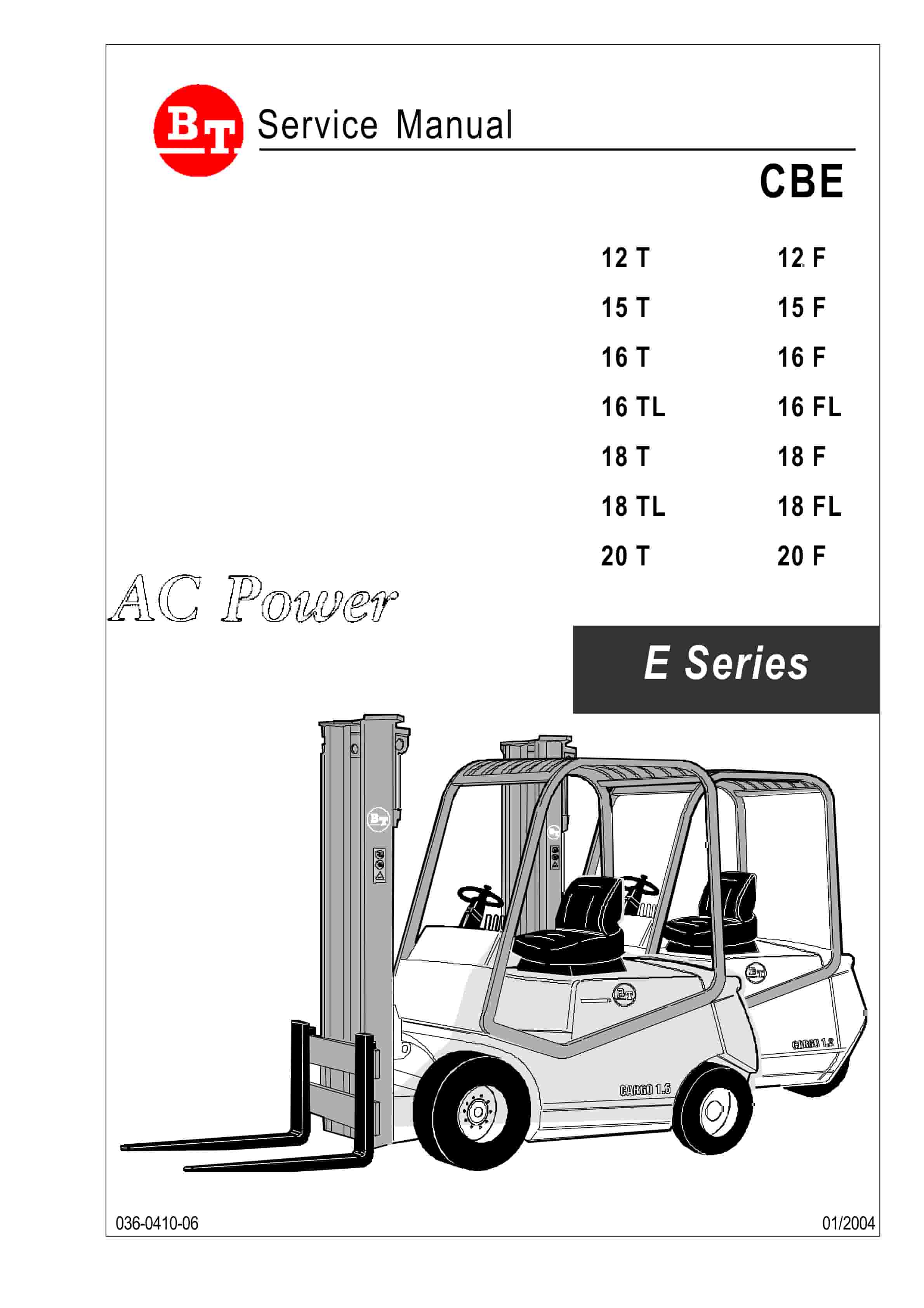
BT CBE 12T to CBE 20F Service Manual 036-0410-03
$30.00 Add to cart -
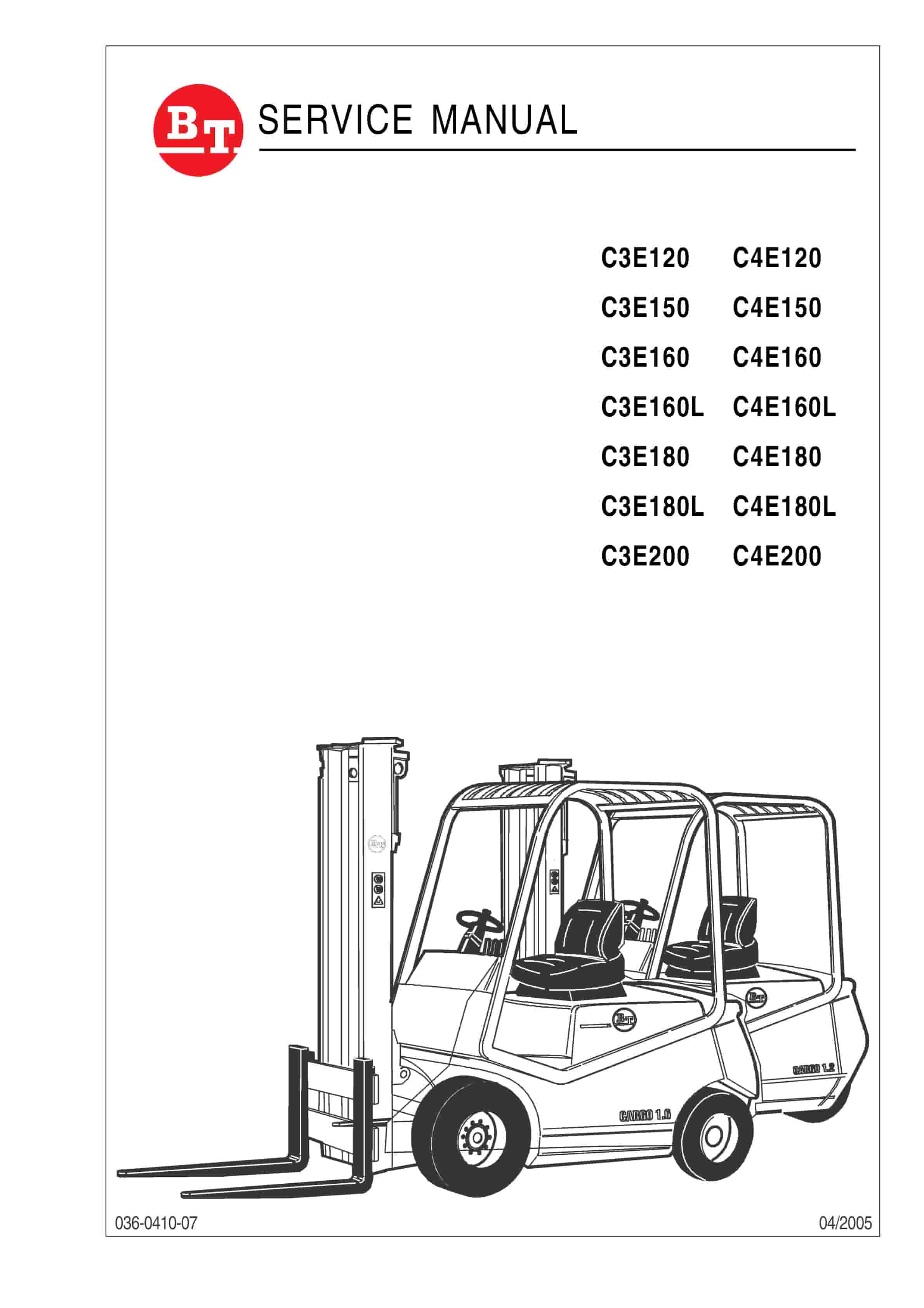
BT C3E120 to C4E200 Service Manual 036-0410-07
$30.00 Add to cart -
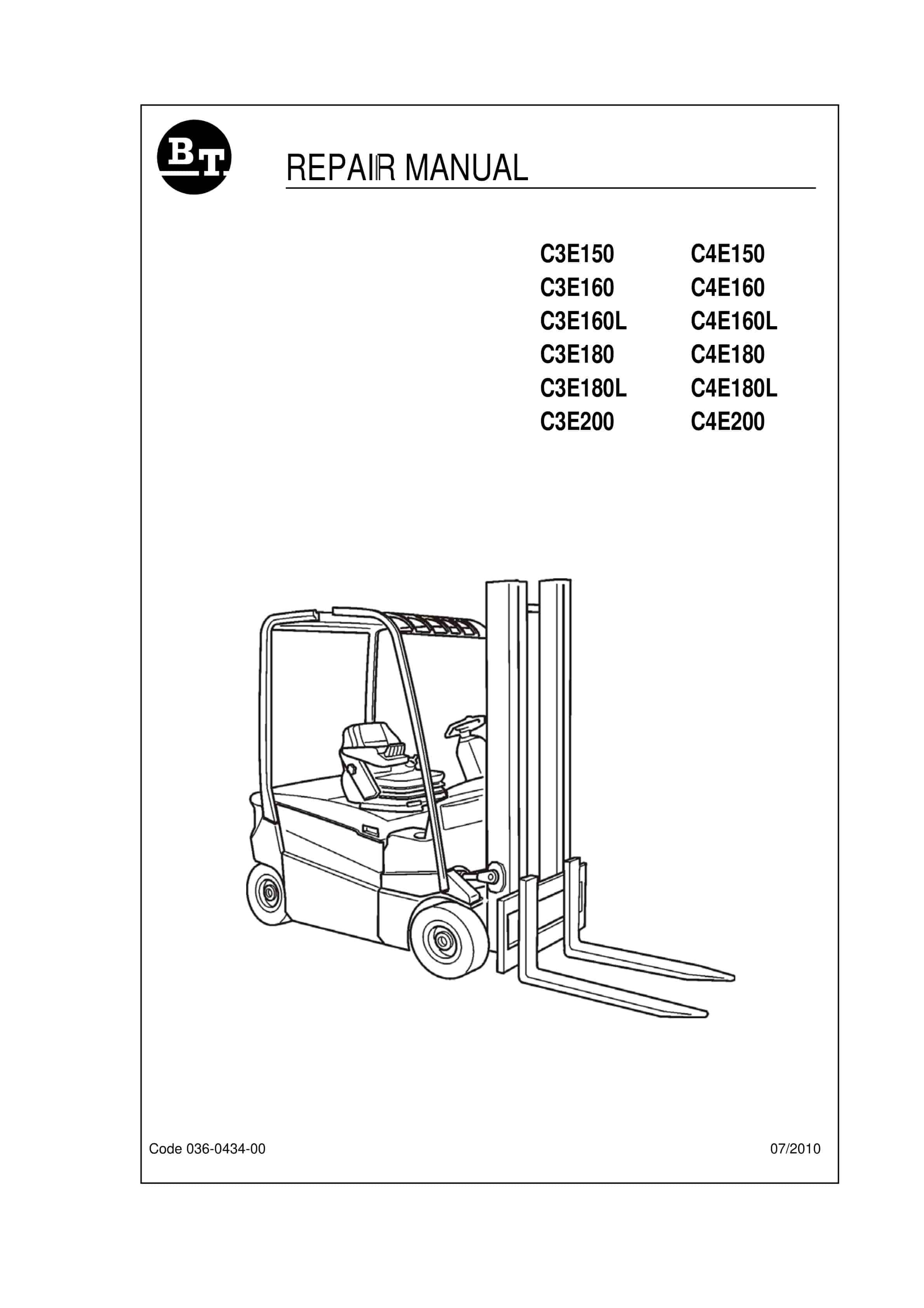
BT C3E150 to C4E200 Repair Manual 036-0434-00
$30.00 Add to cart -
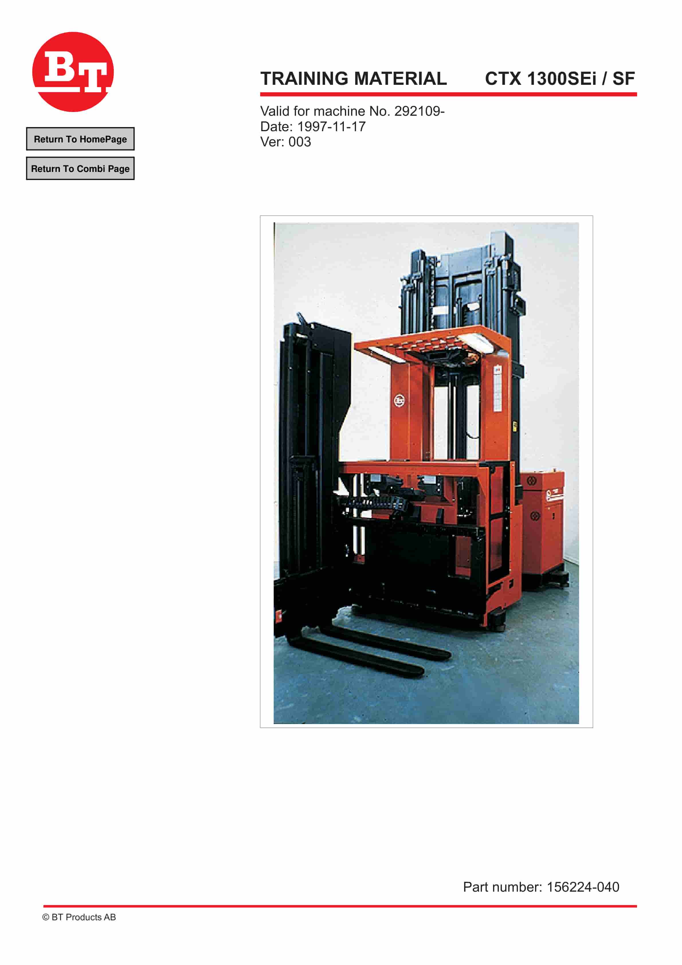
BT CTX 1300SEi, CTX 1300SEi SF Training Material 156224-040
$30.00 Add to cart -
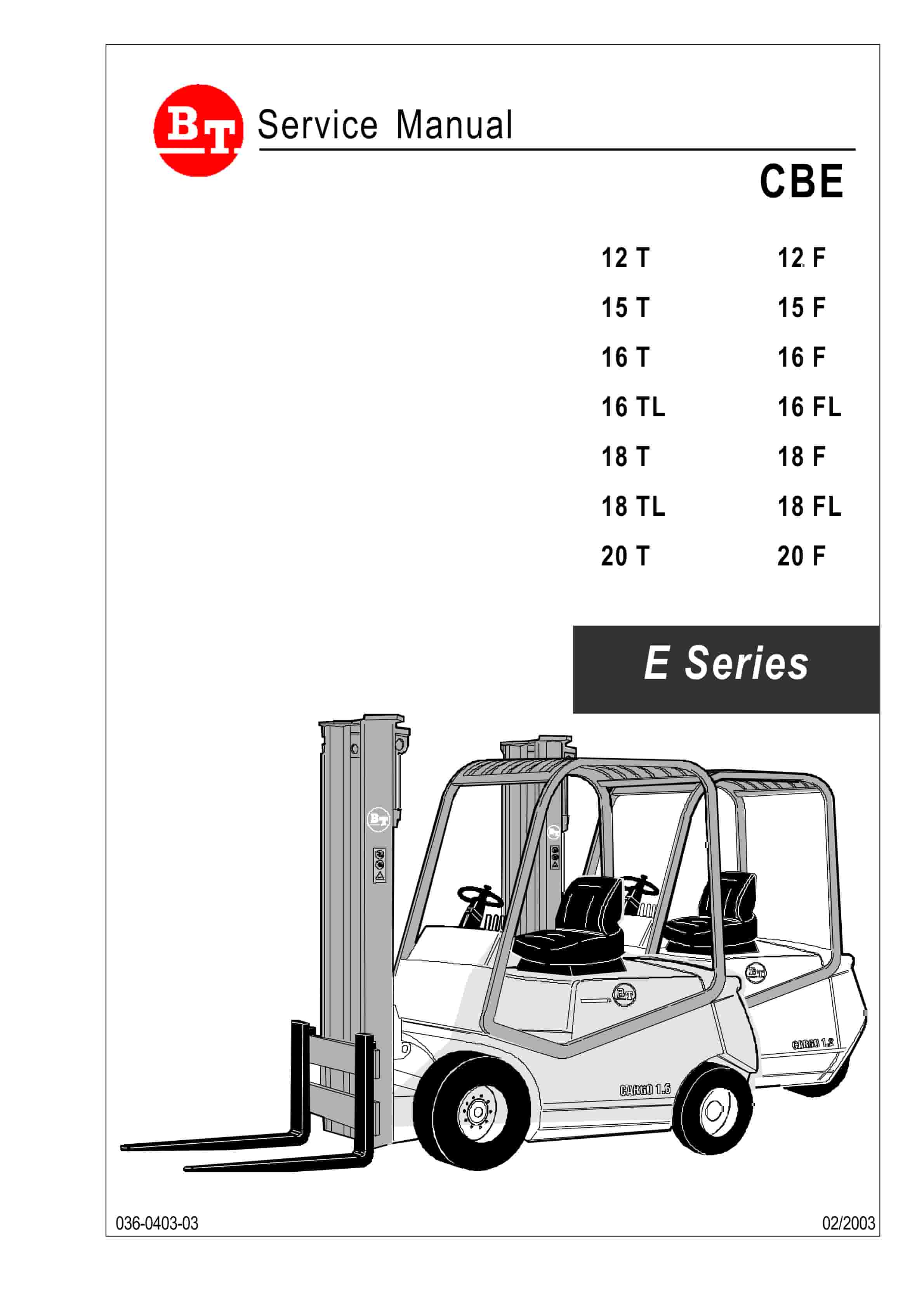
BT CBE 12T to CBE 20F Service Manual 036-0403-03
$30.00 Add to cart


