

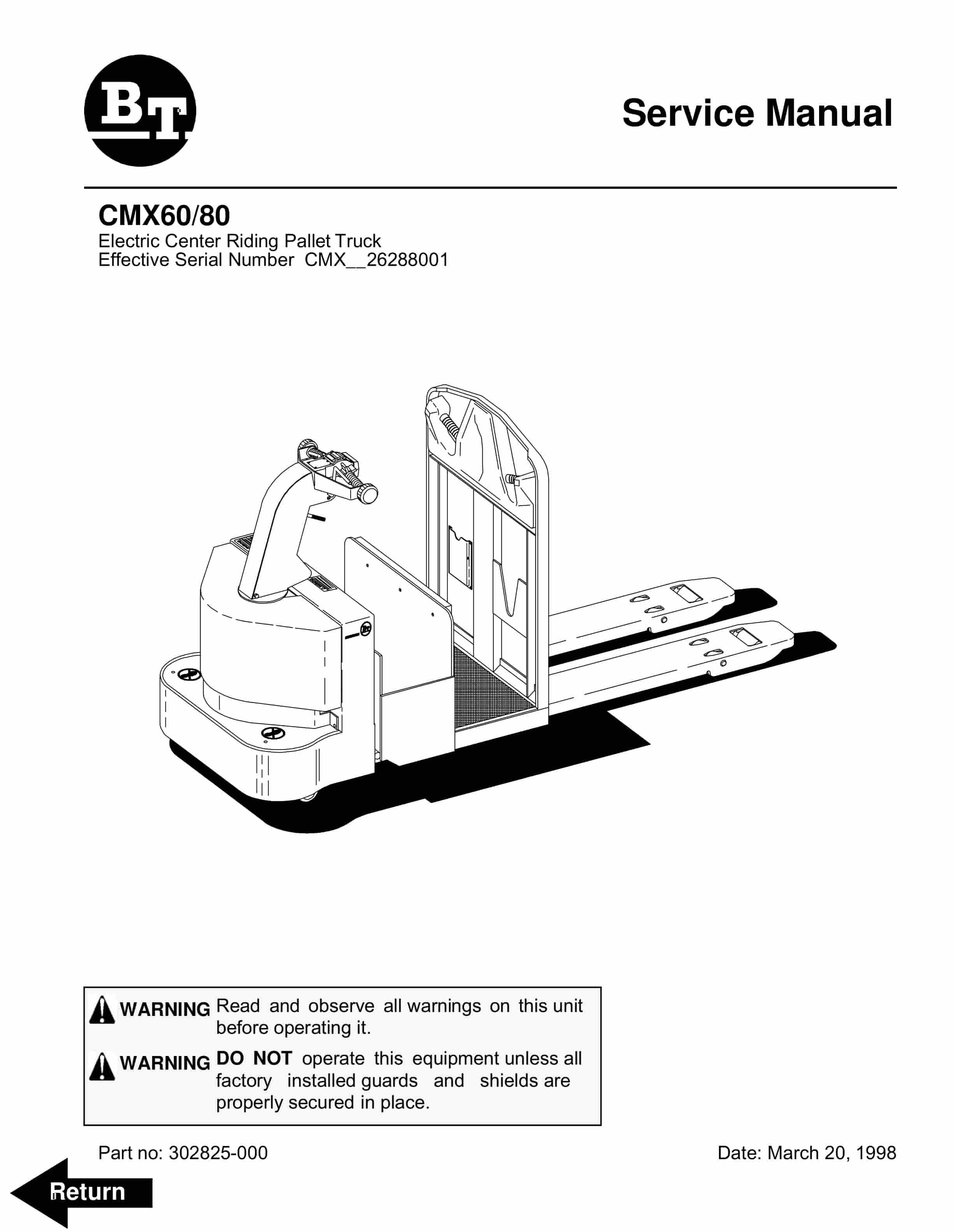
BT CMX60, CMX80 Electric Center Riding Pallet Truck Service Manual 302825-000
$30.00
- Type Of Manual: Service Manual
- Manual ID: 302825-000
- : Service Manual PDF
- Number of Pages: 268
- Size: 3.5MB
- Format: PDF
Product details
-
Model List:
- CMX60, CMX80 Electric Center Riding Pallet Truck
- 1. Front Cover
- 2. BT Standard Codes
- 3. Warning Symbols
- 3.1. Warning Levels
- 4. Prohibitory Symbols
- 4.1. Ordinance Symbols
- 5. Introduction, Service Manual
- 6. Contents, Section M
- 6.1. Machine Information
- 7. General Product Information
- 7.1. Presentation of the Rider Trucks CMX60 and CMX80.
- 7.1.1. Intended Application of the Trucks
- 7.1.2. Forbidden Application of the Trucks
- 7.1.3. Truck Data
- 7.1.4. CMX Dimensions
- 7.1.5. Data Plate
- 8. Inch (SAE) and Metric Fasteners
- 8.1. Introduction
- 9. Technical Service Data
- 10. Ordering Spare Parts
- 11. Contents, Section P
- 11.1. Planned Maintenance
- 12. Introduction, Maintenance
- 12.1. Safe Jacking Procedure
- 13. Service Schedule
- 13.1. Planned Maintenance Schedule
- 13.1.1. Services to be Performed Daily
- 13.1.1.1. Battery Discharge Indicator with slow down
- 13.1.1.2. Hydraulic System
- 13.1.1.3. Frame/Sheet Metal
- 13.1.1.4. Wheels/Tires
- 13.1.1.5. Functions/Operations
- 13.1.2. Services to be Performed Monthly
- 13.1.2.1. Inspection
- 13.1.2.2. Transmission
- 13.1.2.3. Brakes
- 13.1.2.4. Battery
- 13.1.2.5. Electrical Connections
- 13.1.2.6. Contactor Tips (NOT Sealed)
- 13.1.2.7. Motor Brushes
- 13.1.2.8. Drive Motor
- 13.1.2.9. Hydraulic Reservoir
- 13.1.2.10. Frame Lube (Lubrication Chart on page57)
- 13.1.2.11. Pivot Points
- 13.1.3. Services to be Performed Annually
- 13.1.3.1. Inspection
- 13.1.3.2. Transmission
- 13.1.3.3. Battery
- 13.1.3.4. Hydraulic System
- 13.1.3.5. Brakes
- 14. Lubrication Chart
- 15. Oil and Grease Specifications
- 15.1. Approved Oils and Grease
- 16. Contents, Section S
- 16.1. Service Instructions
- 17. Chassis
- 17.1. General Information
- 17.1.1. Removal
- 18. Lift Frame
- 18.1. Pull rod
- 18.1.1. Removal
- 18.1.2. Inspection
- 18.1.3. Installation
- 19. Drive Motor Mounting Points
- 19.1. Drive Motor Brush
- 19.1.1. Removal and Installation
- 19.1.2. Remove
- 19.1.3. Installation
- 20. Drive Motor
- 20.1. General Information
- 21. Drive Motor Service
- 21.1. Motor Repair
- 21.1.1. Disassembly
- 21.1.2. Drive End Head
- 21.1.3. Commutator End Head
- 21.1.4. Bearings
- 21.1.5. Brush and Commutator
- 21.1.6. Armature
- 21.1.7. Frame and Field Assembly
- 21.1.7.1. Testing
- 21.1.7.2. Frame and Field Service Notes
- 21.1.8. Assembly
- 21.1.8.1. Field Coil Installation
- 21.1.8.2. Bearing Installation
- 21.1.8.3. After Assembly
- 22. Transmission
- 22.1. System Description
- 23. Transmission Axle Seal
- 23.1. General Information
- 23.1.1. Removal
- 23.1.2. Installation
- 24. Transmission Disassembly / Assembly
- 24.1. Disassembly
- 25. Parking Brake System
- 25.1. Brake Theory of Operation
- 26. Drive Wheel
- 26.1. Removal
- 26.2. Installation
- 27. Load Wheels
- 28. Support / Swivel Wheel
- 28.1. Stabilizing Caster
- 28.1.1. Removal
- 28.1.2. Inspection
- 28.1.3. Installation
- 28.1.4. Maintenance
- 29. Stabilizing Caster
- 29.1. Stabilizing Caster
- 29.1.1. Disassembly
- 29.1.2. Inspection
- 29.1.3. Assembly
- 30. Steering Control Arm
- 30.1. Control Handle Stem
- 30.1.1. Removal
- 30.1.2. Installation
- 30.1.3. Removal
- 30.1.4. Disassembly
- 30.1.5. Assembly
- 30.1.6. Installation
- 31. Steering Handle Head
- 31.1. Control Handle Head
- 31.1.1. Removal
- 31.1.2. Installation
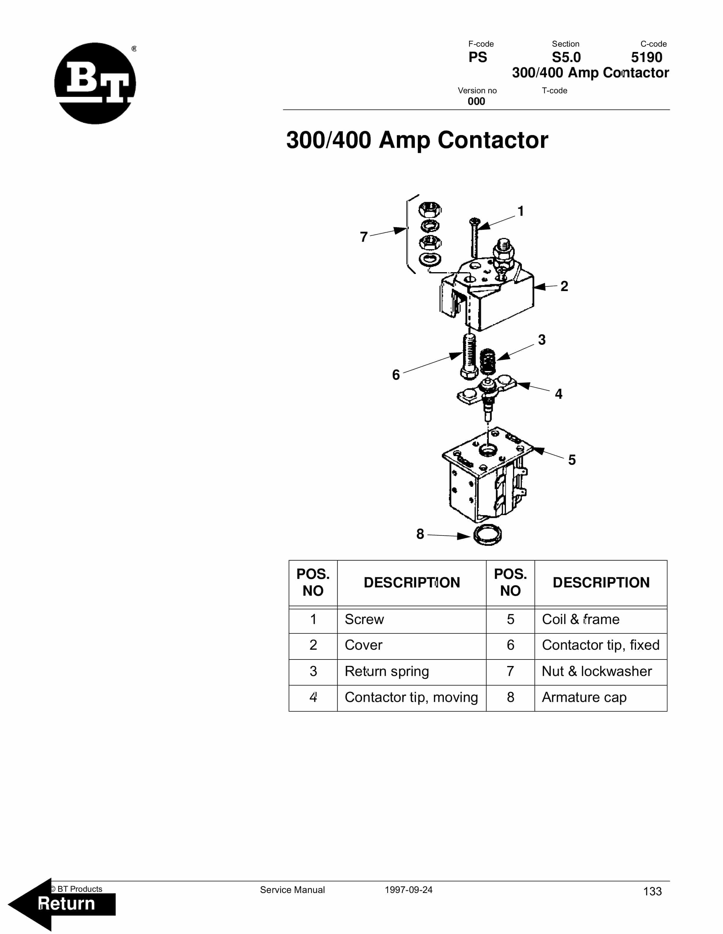
- 32. Amp Contactor
- 32.1. Maintenance
- 32.1.1. Removal/Replacement of Contact Tips
- 33. EE Contactor
- 33.1. Maintenance
- 33.1.1. Removal/Replacement of Contact Tips
- 34. Battery Controller / Hourmeter / Lift Interrupt
- 34.1. General Information
- 34.1.1. Voltage
- 34.1.1.1. The Contact Voltage and Current Ratings for Switching Resistive Loads.
- 34.1.1.2. Memory Retention
- 34.1.2. General Information
- 34.1.2.1. Discharge Adjustment
- 34.1.3. Reset
- 34.1.4. Key Switch
- 34.1.5. Hourmeter
- 34.1.6. Battery Discharge Indicator (BDI)
- 34.1.6.1. No Reset
- 34.1.6.2. Reset After Break in Power
- 34.1.6.3. No Discharge, Gauge Does Not Run Down
- 34.1.6.4. No Lockout
- 34.1.6.5. No Lift
- 34.1.6.6. Early Lockout
- 34.1.6.7. LEDs Do Not Light
- 34.1.7. Hourmeter
- 34.1.7.1. No Display
- 34.1.7.2. Hourmeter Glass Icon Does Not Flash
- 34.1.7.3. Hourmeter Glass Icon Always Flashes
- 35. Battery Discharge Indicator / Hourmeter
- 35.1. General Information
- 35.1.1. Voltage
- 35.1.2. General Information
- 35.1.3. Key Switch
- 35.1.4. Hourmeter
- 35.1.5. Battery Discharge Indicator (BDI)
- 35.1.5.1. No Reset
- 35.1.5.2. Reset After Break in Power
- 35.1.5.3. No Discharge, Gauge Does Not Run Down
- 35.1.5.4. LEDs Do Not Light
- 35.1.6. Hourmeter
- 35.1.6.1. No Display
- 35.1.6.2. Hourmeter Glass Icon Does Not Flash
- 35.1.6.3. Hourmeter Glass Icon Always Flashes
- 36. Volt 400 Amp Electrical System
- 36.1. Electrical Panel Components
- 36.1.1. Circuit Diagram 1(5)
- 36.1.2. Circuit Diagram 2(5)
- 36.1.3. Circuit Diagram 3(5)
- 36.1.4. Circuit Diagram 4(5)
- 36.1.5. Circuit Diagram 5(5)
- 36.1.6. General Information
- 36.1.7. References Information
- 36.1.8. Key Switch S17 in the ON Position
- 36.1.9. Brake released, S10 Brake Switch Closed
- 36.1.10. Driving, Fork Direction
- 36.1.11. Driving, Steer Wheel Direction
- 36.1.12. Reversing/Motor Brake Fork Direction to Steer Wheel Direction
- 36.1.13. Reversing/Motor Brake Steer Wheel Direction to Fork Direction
- 36.1.14. Lifting the Forks
- 36.1.15. Lowering the Forks
- 36.1.16. Horn
- 36.1.17. Prime-Trak operator off of the truck
- 36.1.18. Prime-Trak operator on the truck
- 36.1.19. Lift Interrupt
- 37. Volt, 400 Amp Transistor Controller
- 37.1. Maintenance
- 37.1.1. Safety
- 37.1.2. Cleaning
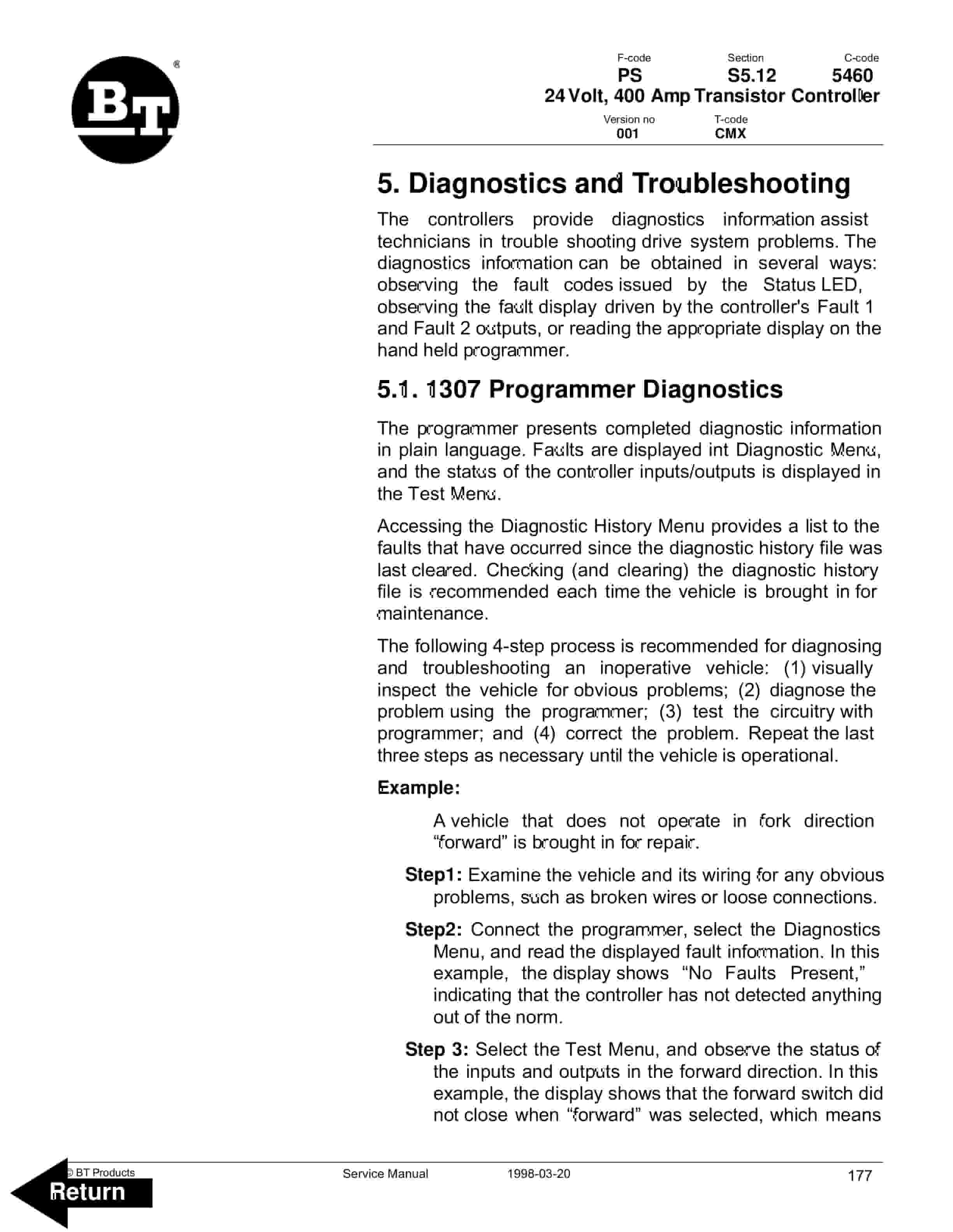
- 37.1.3. Diagnostics and Troubleshooting
- 37.1.3.1. Handset Diagnostics
- 37.1.3.2. Troubleshooting
- 37.1.4. Control Features
- 37.1.5. Programmer Diagnostics
- 37.1.6. Troubleshooting Chart
- 37.1.7. Technical Specification
- 37.1.8. Troubleshooting Chart Using the Handset
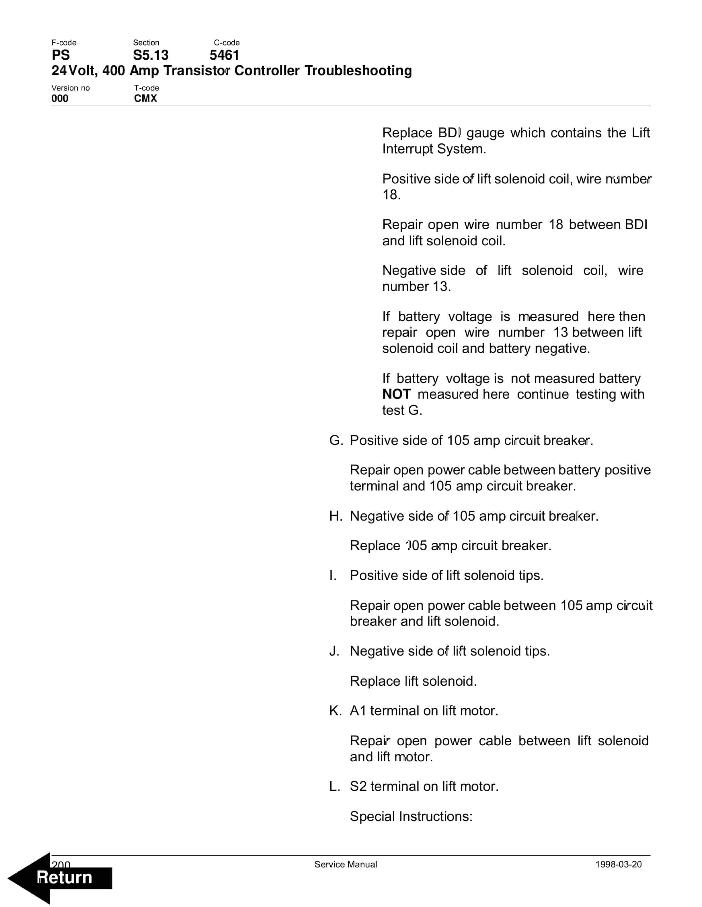
- 38. Volt, 400 Amp Transistor Controller Troubleshooting
- 38.1. Troubleshooting Chart Index
- 39. Handset Operation
- 39.1. Operating Modes
- 40. Pump Motor
- 40.1. Component Repair
- 40.1.1. Motor Disassembly
- 40.1.2. Drive End Head
- 40.1.3. Commutator End Head
- 40.1.4. Bearings
- 40.1.5. Brush and Commutator
- 40.1.6. Armature
- 40.1.7. Frame and Field Assembly
- 40.1.7.1. Testing
- 40.1.7.2. Frame and Field Service Notes
- 40.1.8. Assembly
- 40.1.8.1. Field Coil Installation
- 40.1.8.2. Bearing Installation
- 40.1.8.3. After Assembly
- 41. Hydraulic System
- 41.1. Hydraulic Schematic
- 41.1.1. Lift
- 41.1.2. Lower
- 41.1.3. Relief Pressure
- 42. Prime-Trak Hydraulic System
- 42.1. Prime-Trak Hydraulic Schematic
- 43. Lift Pump Assembly
- 43.1. Removal
- 43.1.1. Relief valve
- 43.1.2. Solenoid Operated Valve
- 44. Prime-Trak Hydraulic Pump
- 44.1. Removal
- 45. Lift Cylinder
- 45.1. Removal
- 46. Prime-Trak Cylinders
- 46.1. Removal
- 47. Back Cover
Related products
-
BT CBE 25, CBE 30, CBE 30L, CBE 35 Service Manual 036-0402-02
$30.00 Add to cart -
BT CBE 12T to CBE 20F Service Manual 036-0410-03
$30.00 Add to cart -
BT C3E120 to C4E200 Service Manual 036-0410-07
$30.00 Add to cart -
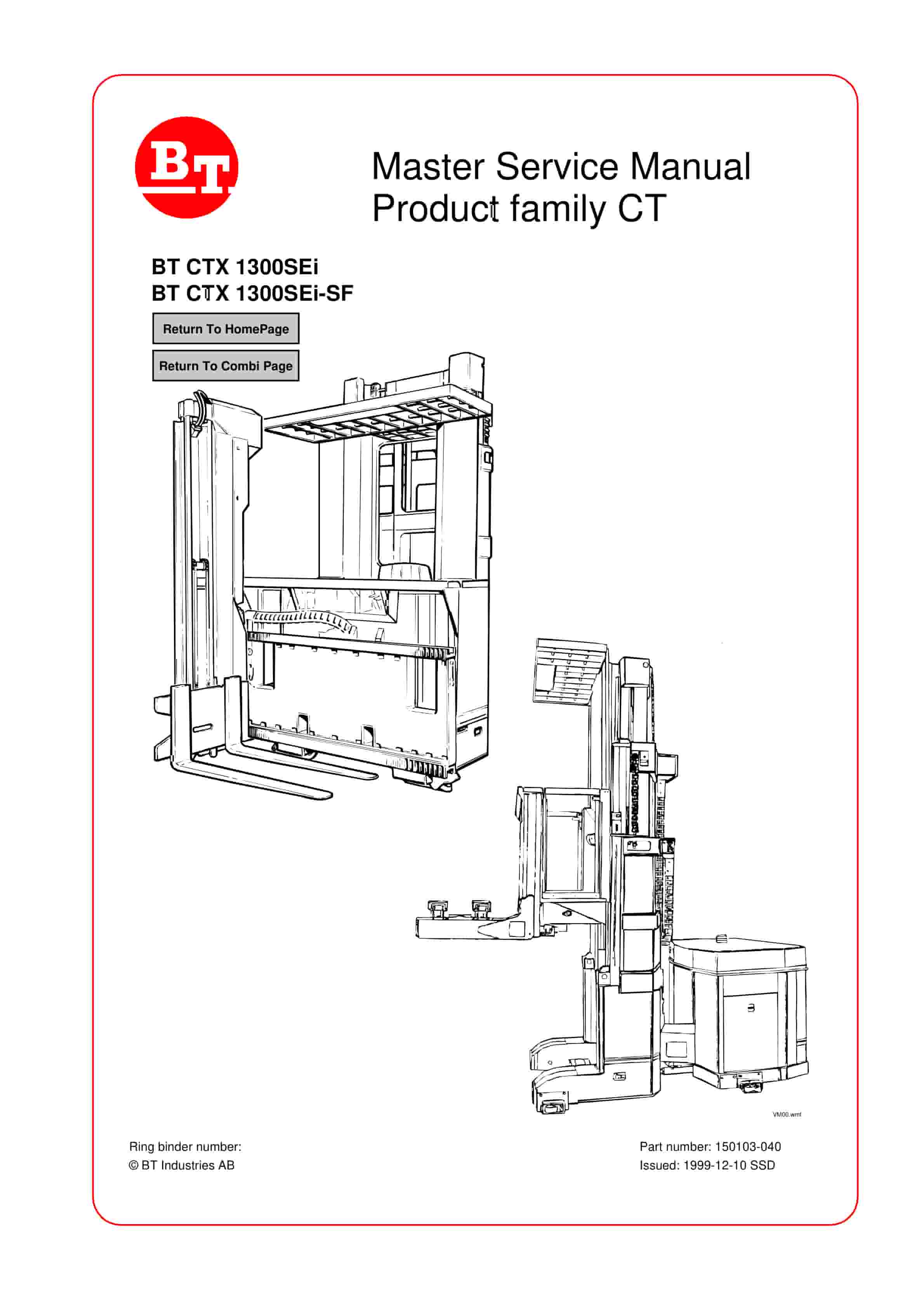
BT CTX 1300SEi, CTX 1300SEi SF Service Manual 150103-040
$30.00 Add to cart -
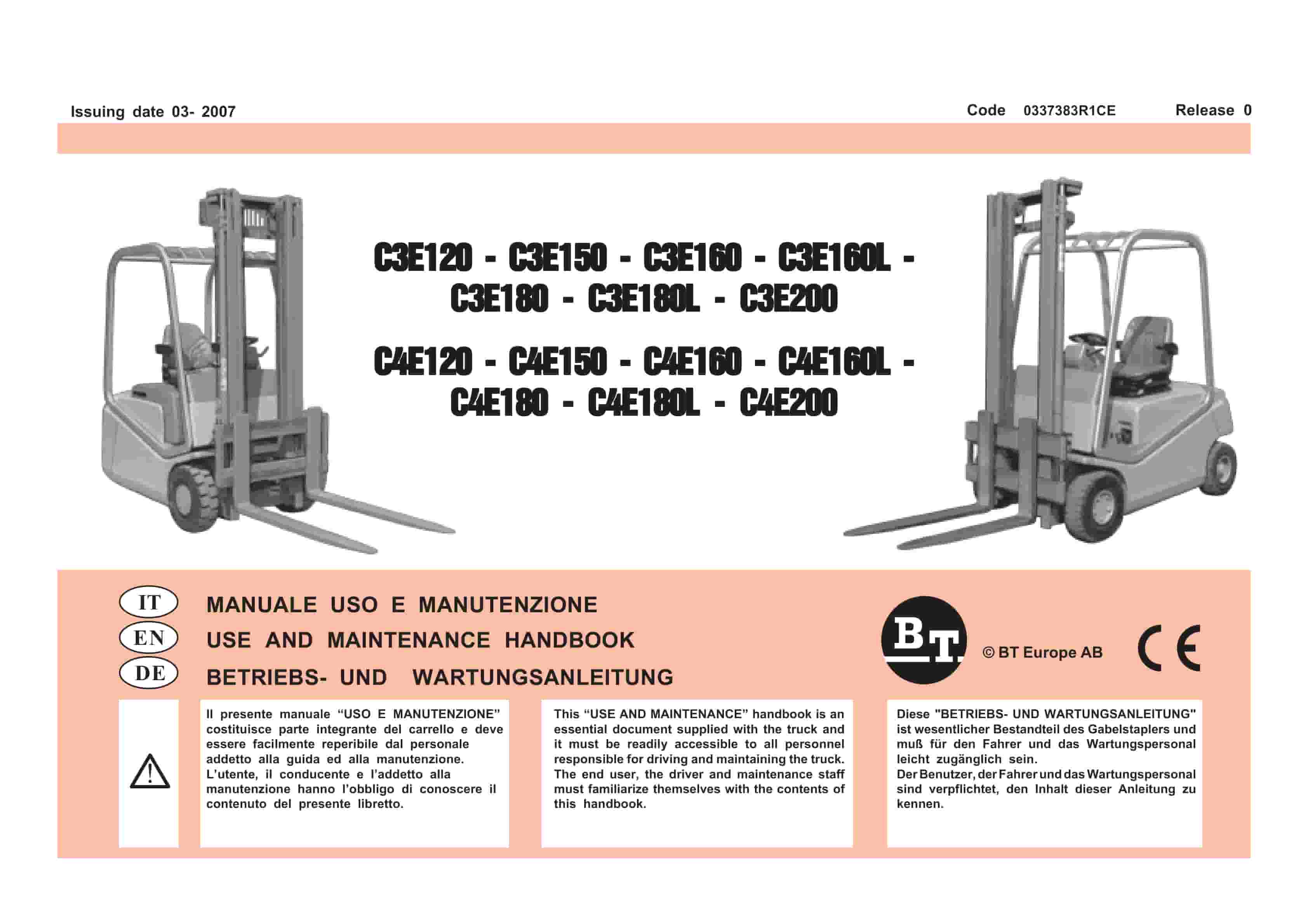
BT C3E120 to C4E200 Use And Maintenance Handbook 0337383R1CE
$30.00 Add to cart


