


BT Service Manual PDF
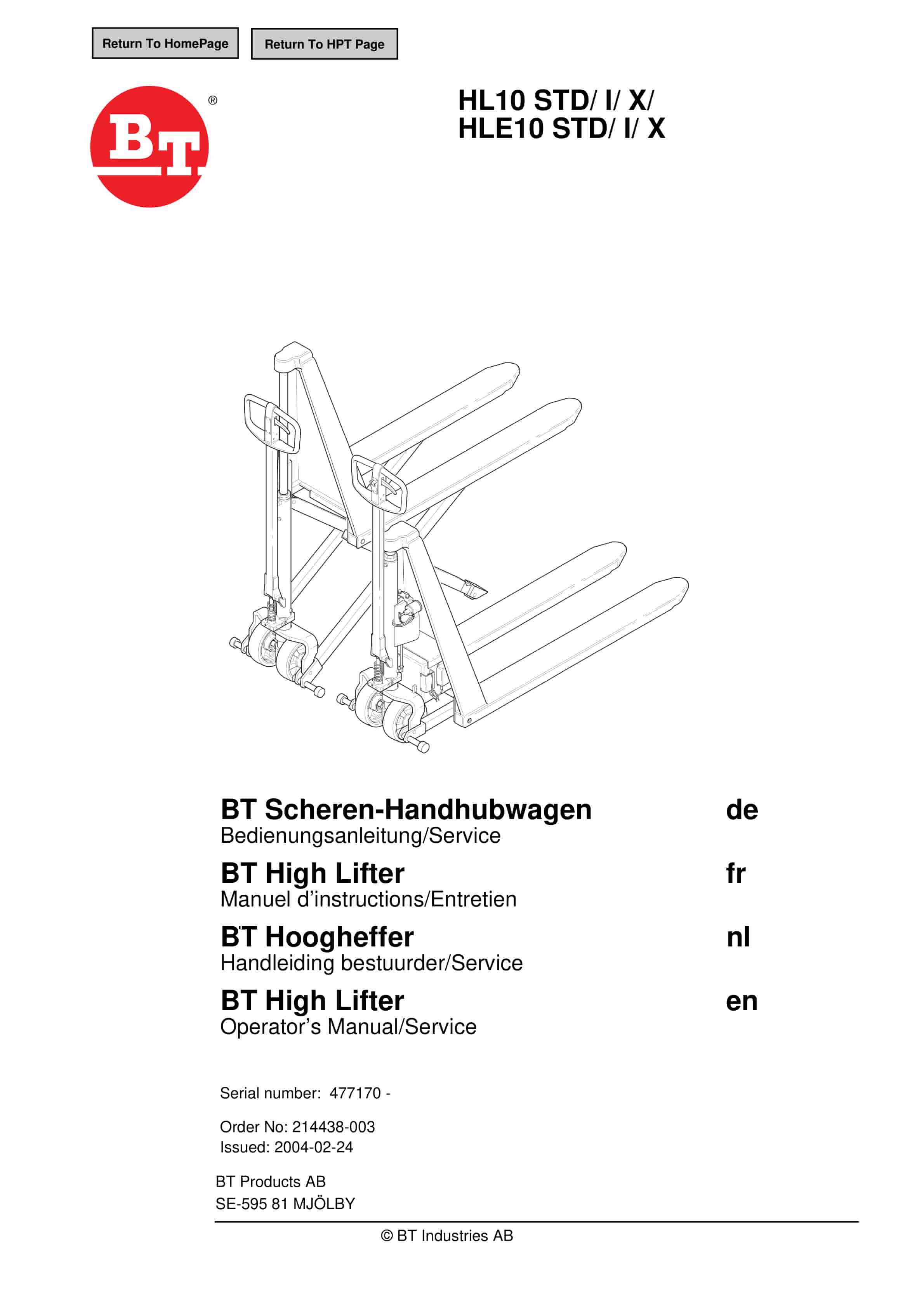
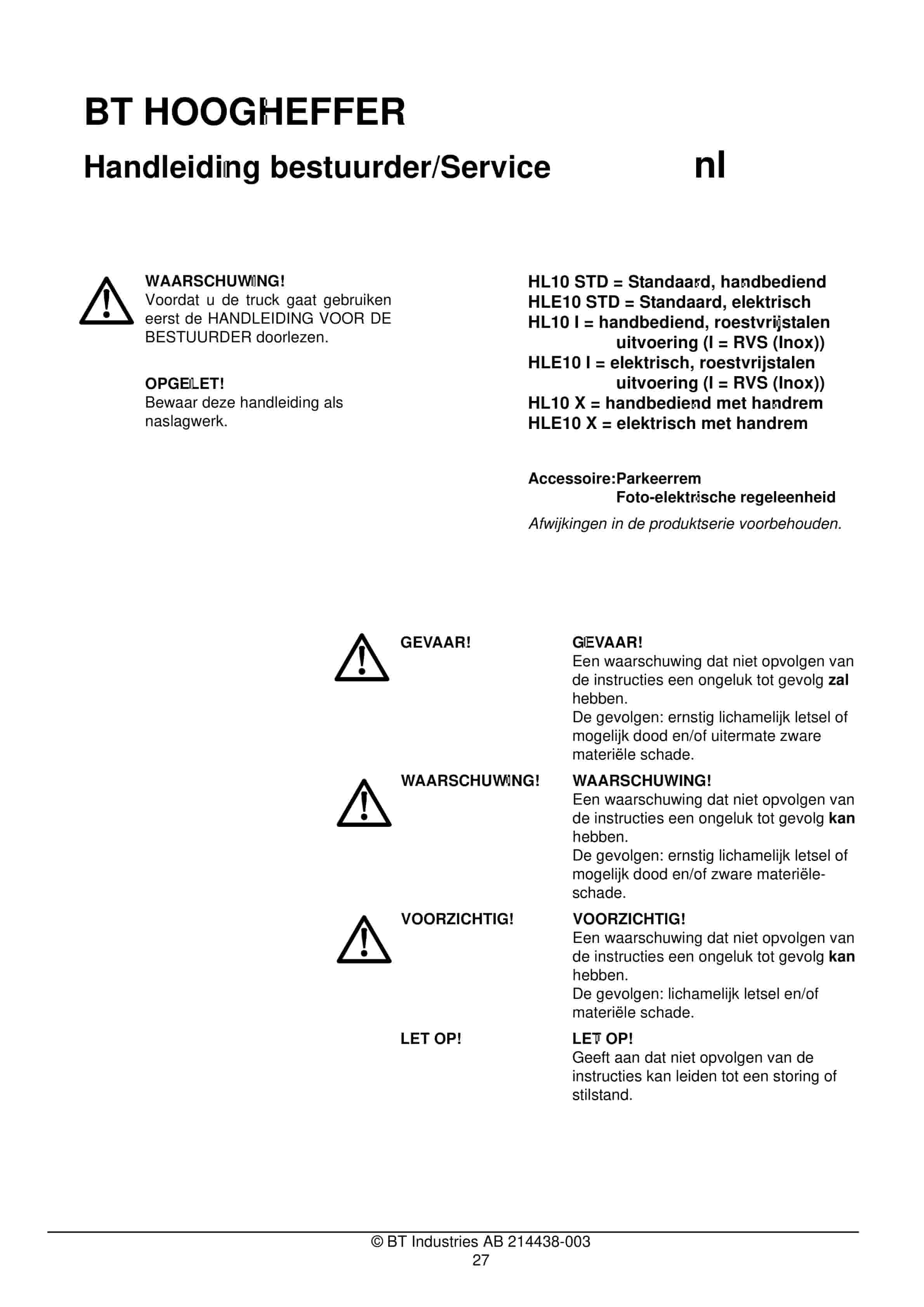
BT HL10 STD, HL10 I, HL10 X, HLE10 STD, HLE10 I, HLE10 X Operator And Service Manual 214438-003
$30.00
BT Service Manual PDF
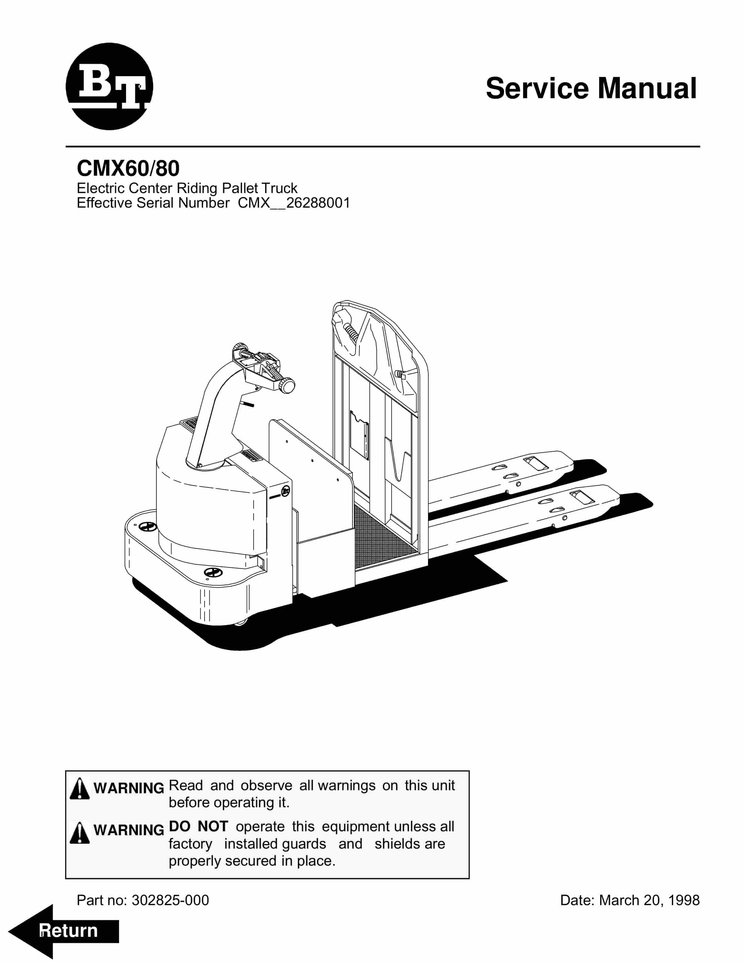
BT CMX60, CMX80 Electric Center Riding Pallet Truck Service Manual 302825-000
$30.00
BT Service Manual PDF
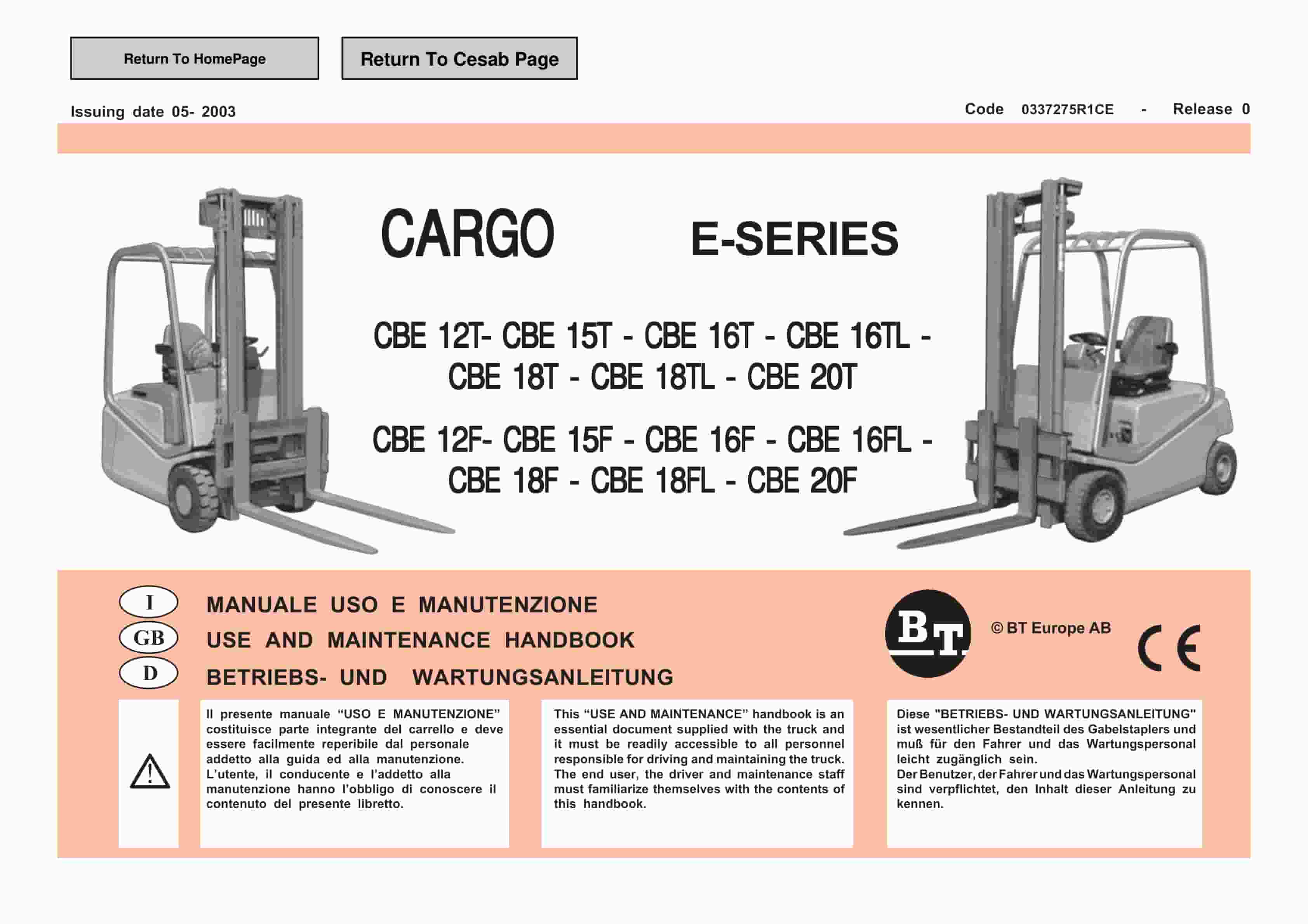
BT CARGE E-Series CBE 12T-20T, CBE 12F-20F Use And Maintenance Handbook 0337275R1CE
$30.00