

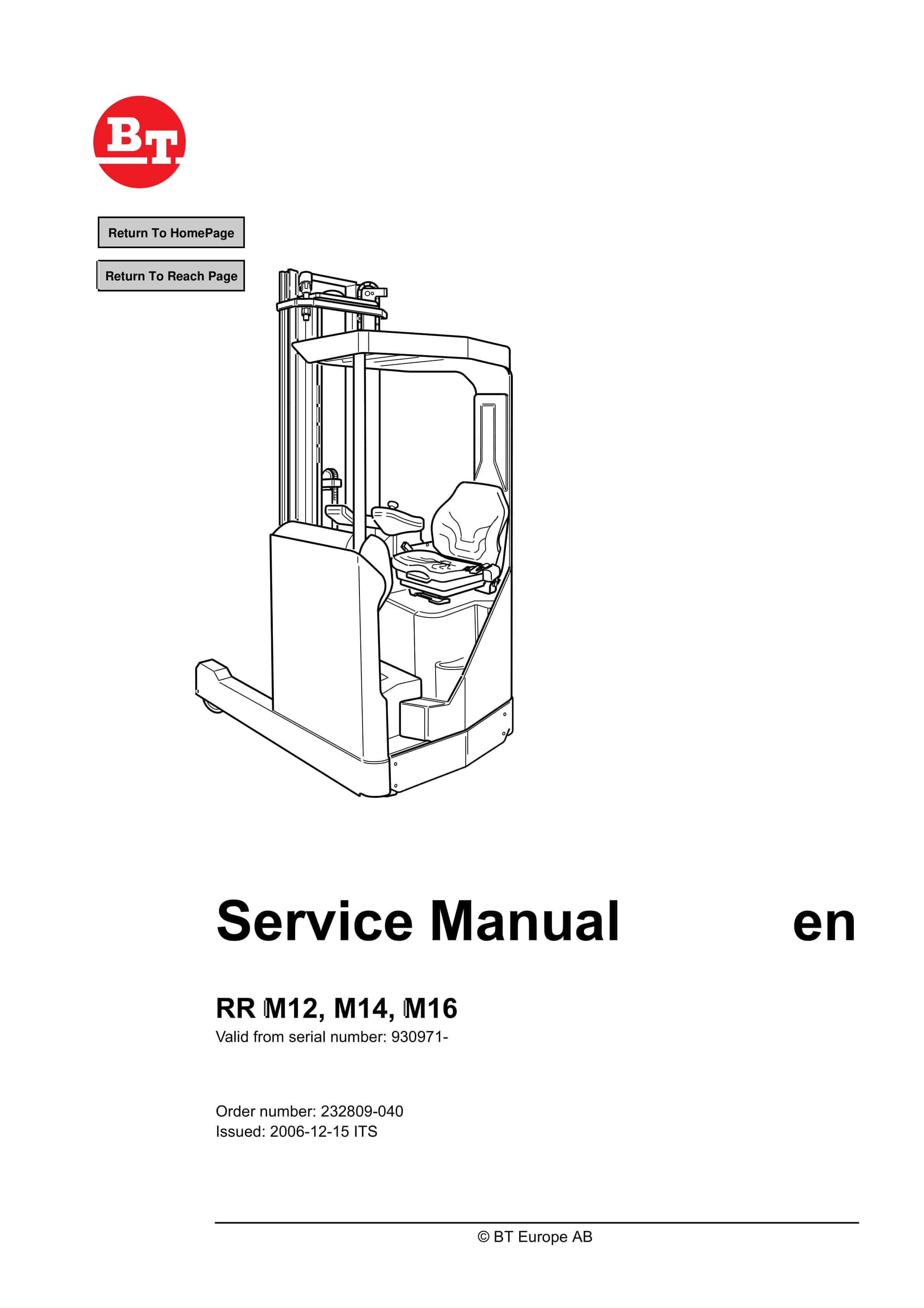
BT RR M12, RR M14, RR M16 Service Manual 232809-040
$30.00
- Type Of Manual: Service Manual
- Manual ID: 232809-040
- : Service Manual PDF
- Number of Pages: 424
- Size: 13.5MB
- Format: PDF
Product details
-
Model List:
- RR M12, RR M14, RR M16
- 1. Return To HomePage
- 2. Table of contents
- 3. Technical data – M4
- 3.1. General tightening torques
- 3.1.1. Galvanised, non-oiled bolts
- 3.1.2. Untreated, oiled bolts
- 4. Introduction, maintenance – P1
- 4.1. Safety regulations with maintenance work
- 4.2. Cleaning and washing
- 4.2.1. External cleaning
- 4.2.2. Cleaning the motor compartment
- 4.2.3. Electrical components
- 4.3. Safe lifting
- 5. Preventive Maintenance – P2
- 5.1. Maintenance schedule
- 6. Oil and grease specification – P3
- 7. Tools – P4
- 7.1. Super Seal contact
- 7.1.1. AMP connector
- 7.1.2. AMP microtimer
- 7.1.3. Various tools
- 8. Driver Protection – 0840
- 8.1. General
- 8.2. Tilt stops
- 8.2.1. Removing the tilt stops
- 9. Power electronics panel – 5660
- 9.1. General description
- 9.1.1. Terminal connections and pole bolts
- 9.1.2. Technical Data
- 9.1.3. Installing a new transistor panel
- 9.2. Diagnostics and trouble shooting
- 9.2.1. Displaying error codes, logging errors
- 9.2.2. Error codes, trouble shooting
- 9.2.3. Resetting an error
- 9.3. Maintenance
- 9.3.1. Safety
- 9.3.2. Cleaning
- 10. Electric Pump Motor – 1710
- 10.1. General
- 10.2. Dismantling the Pump Motor
- 10.2.1. Connection
- 10.3. Removing and replacing the pump motor
- 10.3.1. Dismantling
- 10.3.2. Assembling
- 10.4. Bearing replacement
- 10.4.1. Dismantling (D side)
- 10.4.2. Assembling
- 10.4.3. Dismantling (N side)
- 10.4.4. Assembling (N side)
- 10.4.5. Carbon brushes and brush holders
- 11. Electric steering motor – 1730
- 11.1. General
- 11.2. Replacing the steering motor
- 11.2.1. Dismantling
- 11.2.2. Assembling
- 11.3. Removing and replacing the carbon brushes
- 12. Electric drive motor – 1760
- 12.1. General
- 12.2. Dismantling the drive motor
- 12.3. Dismantling and assembling the drive motor
- 12.3.1. Dismantling the drive motor
- 12.3.2. Assembling the drive motor
- 12.3.3. Reset the truck
- 12.4. Bearing replacement
- 12.4.1. Dismantling
- 12.4.2. Assembling
- 12.5. Installation instructions for external temperature sensor
- 13. Mechanical drive gear unit – 2550
- 13.1. General
- 13.2. Components/data for the drive assembly/transmission
- 13.2.1. Component placement
- 13.2.2. Technical data
- 13.2.3. Dismantling the transmission
- 13.3. Replacing the drive motor/drive transmission
- 13.3.1. Dismantling the drive motor
- 13.3.2. Dismantling the drive transmission
- 13.3.3. Assembling the transmission
- 13.3.4. Installing the drive motor
- 13.3.5. Reset the truck
- 13.4. Checking/replacing the oil
- 13.4.1. Checking/refilling the oil
- 13.4.2. Changing the Oil
- 13.5. Repairs
- 13.5.1. Replacing the drive shaft sealing ring
- 13.5.2. Leakage from the upper cover
- 13.5.3. Leakage from the lower cover
- 13.5.4. Replacing wheel bolts
- 14. Travel brake system – 3100
- 14.1. General
- 14.2. Operating description
- 14.2.1. Releasing the accelerator
- 14.2.2. Travel direction selector
- 14.2.3. Pressing down the brake pedal
- 14.2.4. Parking brake
- 14.2.5. Emergency brake
- 14.3. Electromechanical disc brake, drive motor
- 14.4. Disassembly
- 14.5. Inspection
- 14.6. Assembly
- 14.7. Maintenance
- 14.7.1. Adjusting the play
- 14.7.2. Wear
- 14.7.3. Checking the braking force
- 15. Drive wheel – 3530
- 15.1. General
- 15.2. Dismantling the drive wheel
- 15.3. Assembling the drive wheel
- 16. Fork/support arm wheel – 3550
- 16.1. General
- 16.2. Dismantling the wheel
- 16.3. Assembling the drive wheel
- 16.4. Dismantling the wheel bearing
- 16.5. Assembling the wheel bearing
- 17. Mechanical steering system – 4100
- 17.1. General
- 17.2. Replacing the steering generator
- 17.2.1. Dismantling
- 17.2.2. Assembling
- 18. Steering angle sensor – 4350
- 18.1. General
- 18.2. Procedure
- 18.2.1. Adjustment of the steering angle sensor
- 19. Electrical System – 5000
- 19.1. General
- 19.1.1. Electrical Panel
- 19.2. Symbol List and Electrical Diagrams
- 19.2.1. Symbol List
- 19.2.2. Electrical Diagrams
- 19.2.3. Component List
- 19.2.4. Figure 1
- 19.2.5. Figure 2
- 19.2.6. Figure 3
- 19.2.7. Figure 4
- 19.2.8. Figure 5
- 19.2.9. Figure 6
- 19.2.10. Figure 7
- 19.2.11. Figure 8
- 19.3. Functional Description
- 19.3.1. Key in Position 0
- 19.3.2. Key in Position I
- 19.3.3. Choice of travel direction
- 19.3.4. Driving
- 19.3.5. Steering
- 19.3.6. Steering wheel indicator
- 19.3.7. Braking
- 19.3.8. Fork lifting
- 19.3.9. Maximum height
- 19.3.10. Maximum height
- 19.3.11. Fork lowering
- 19.3.12. Mast out/in
- 19.3.13. Fork tilt up/down
- 19.3.14. Hydraulic function 4
- 19.3.15. Hydraulic function 5
- 19.3.16. Height indicator
- 19.3.17. Preset height
- 19.3.18. Driver identification
- 20. Battery – 5110
- 20.1. Battery dimensions
- 20.2. Setting the battery parameters on RR trucks fitted with Hawker Evolution gel batteries
- 20.2.1. General
- 20.2.2. Battery recommendation
- 20.2.3. Battery installation
- 20.2.4. Recommended parameter setting for ventilation regulated batteries
- 20.2.5. Instructions for verifying the parameter setting
- 21. Transistor panel – 5460
- 21.1. Frequency converter
- 21.1.1. Terminal connections and pole bolts
- 21.1.2. Technical Data
- 21.1.3. Programming
- 22. Electronic card – 5710
- 22.1. General description
- 22.2. Terminal connections and voltages on A5
- 22.2.1.
- 22.2.2.
- 22.2.3.
- 22.2.4.
- 22.2.5.
- 22.2.6.
- 22.2.7.
- 22.2.8.
- 22.2.9.
- 22.3. Adjusting the lowering speed
- 22.4. Show
- 22.5. Programming
- 22.5.1. Driver parameters (1-7)
- 22.6. Warning Codes
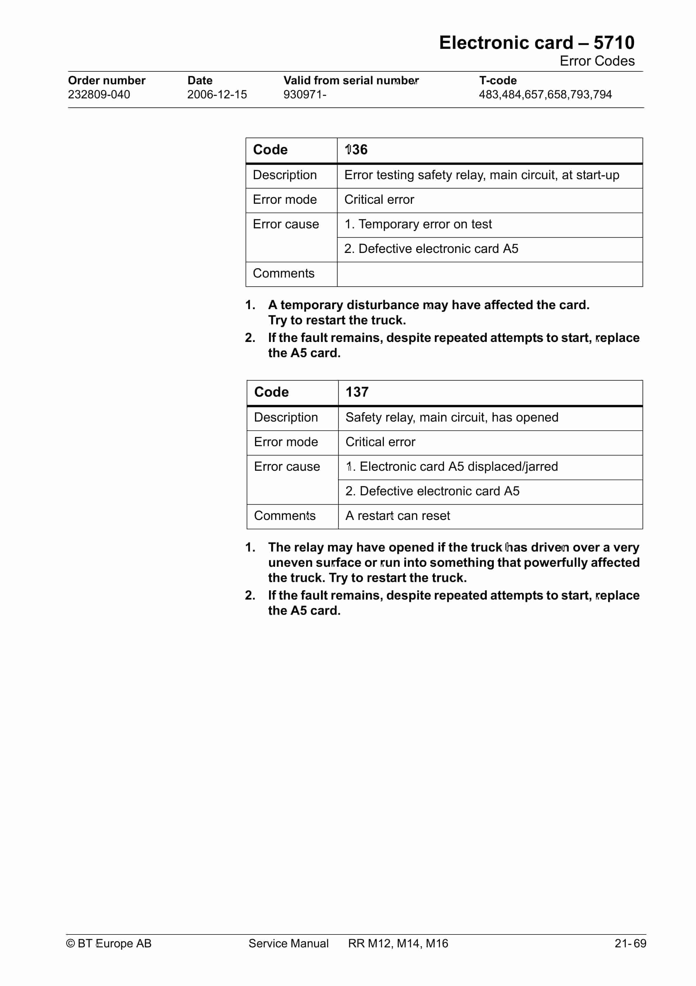
- 22.7. Error Codes
- 22.7.1. Safety logic
- 22.7.2. Warning Codes without registration
- 22.8. Warning codes with registration
- 22.9. Error Codes
- 22.9.1. Error codes with registration
- 22.10. Operating Time
- 22.11. Parameter Settings
- 22.11.1. Parameter 1
- 22.11.2. Parameter 2
- 22.11.3. Parameter 3
- 22.11.4. Parameter 4
- 22.11.5. Parameter 5
- 22.11.6. Parameter 10
- 22.11.7. Parameter 11
- 22.11.8. Parameter 12
- 22.11.9. Parameters 13 to 14
- 22.11.10. Parameters 15 and 16
- 22.11.11. Parameters 17 and 18
- 22.11.12. Parameter 19
- 22.11.13. Parameter 20
- 22.11.14. Parameter 21
- 22.11.15. Parameter 23
- 22.11.16. Parameter 24
- 22.11.17. Parameter 25
- 22.11.18. Parameter 26
- 22.11.19. Parameter 27
- 22.11.20. Parameter 28
- 22.11.21. Parameter 29
- 22.11.22. Parameter 38
- 22.11.23. Parameter 39
- 22.11.24. Parameters 40 to 42
- 22.11.25. Other parameters
- 22.11.26. Installing a new card in the truck
- 23. Hydraulic system – 6000
- 23.1. General
- 23.2. Symbols
- 23.2.1. Hydraulic chart 1 (3)
- 23.2.2. Hydraulic chart 2 (3)
- 23.2.3. Hydraulic chart 3 (3)
- 23.3. List of symbols
- 23.3.1. Component placement 1 (2)
- 23.3.2. Component placement 2 (2)
- 23.4. Adjusting fork lowering
- 23.5. Setting the max lifting capacity
- 24. Hydraulic pump – 6140
- 24.1. General
- 24.2. Replacing the hydraulic pump
- 24.2.1. Dismantling
- 24.2.2. Assembling
- 25. Hydraulic connections – 6230
- 25.1. General
- 25.2. Tightening torque for hydraulic connections
- 25.2.1. Conical connection with O-ring
- 25.2.2. Tredo seal
- 25.2.3. Pipe coupling
- 25.2.4. Connection screwed into aluminium
- 25.2.5. Connection screwed into steel
- 26. Hydraulic cylinder – 6600
- 26.1. General
- 26.2. Duplex mast
- 26.2.1. Dismantling the lift cylinders from the mast
- 26.2.2. Dismantling the cylinder
- 26.2.3. Dismantling the rod seal, guide ring, guide ring holder and locking ring in lift cylinder
- 26.2.4. Assembling the locking ring, rod seal, guide ring and guide ring holder in the lift cylinder
- 26.2.5. Dismantling and assembling the lower brake valve
- 26.2.6. Assembling the cylinder
- 26.2.7. Assembling the cylinder in the mast
- 26.3. Triplex mast
- 26.3.1. Dismantling the free lift cylinder from the mast
- 26.3.2. Dismantling the mast lift cylinders from the mast
- 26.4. Cylinder seals
- 26.5. Replacing wear parts in the cylinder
- 26.5.1. Securing
- 26.5.2. Dismantling the cylinder
- 26.5.3. Replacing the lower support ring
- 26.5.4. Replacing the O-ring on the top sleeve
- 26.5.5. Replacing the internal wear parts in the top sleeve
- 26.5.6. Assembling the cylinder
- 26.5.7. Assembling the free lift cylinder in the mast
- 26.5.8. Assembling the mast lift cylinder
- 27. Mast mounted hose reel – 6370
- 27.1. General
- 27.2. Assembling
- 27.3. Check after assembly
- 28. Main lift cylinder – 6610
- 28.1. General
- 28.2. Tools
- 28.3. Dismantling the lift cylinders from the mast
- 28.4. Dismantling the cylinder
- 28.4.1. Dismantling the rod seal, guide ring, guide ring holder and locking ring in lift cylinder
- 28.4.2. Fit the locking ring, rod seal, guide ring and guide ring holder in the lift cylinder
- 28.4.3. Dismantling and assembling the hose rupture valve
- 28.5. Assembling the cylinder
- 28.5.1. Assembling the cylinder in the mast
- 29. Free lift cylinder – 6620
- 29.1. General
- 29.2. Tools
- 29.3. Dismantling
- 29.3.1. Dismantling the cylinder
- 29.4. Dismantle the rod seal and the support rin
- 29.4.1. Assembling the rod seal and the support ring.
- 29.5. Dismantling the ram
- 29.5.1. Assembling the ram in the free lift cylinder
- 29.6. Dismantling and assembling the hose rupture valve
- 29.7. Assembling the cylinder
- 29.8. Assembling
- 30. Reach cylinder – 6650
- 30.1. General
- 30.2. Assembling and dismantling the reach cylinder
- 30.2.1. Dismantling the cylinder
- 30.2.2. Dismantling the rod
- 30.2.3. Dismantle the to sleeve seals
- 30.2.4. Assembling the top sleeve
- 30.2.5. Fit the ram seal
- 30.2.6. Dismantling the rod
- 30.2.7. Assembling the cylinder
- 30.3. Assembling
- 31. Tilt cylinder – 6660.1
- 31.1. General
- 31.2. Assembling and dismantling the tilt cylinder
- 31.2.1. Dismantling the cylinder
- 31.2.2. Dismantling the rod
- 31.2.3. Dismantling the ram seals
- 31.2.4. Dismantle the top sleeve seals
- 31.2.5. Assembling the top sleeve
- 31.2.6. Assembling the ram seal
- 31.2.7. Dismantling the rod
- 31.2.8. Assembling the cylinder
- 31.3. Assembling
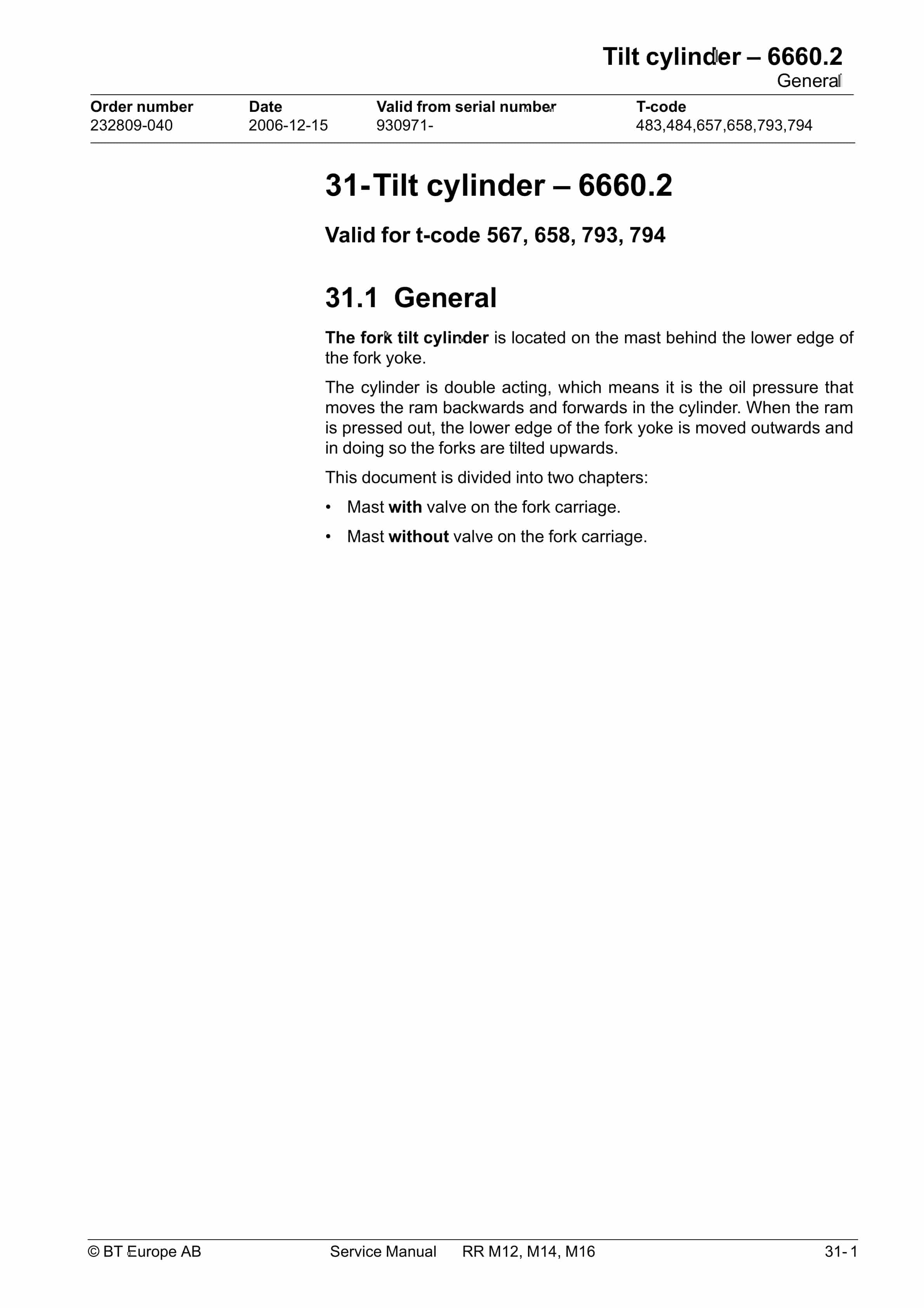
- 32. Tilt cylinder – 6660.2
- 32.1. General
- 32.2. Mast with valve on the fork carriage
- 32.2.1. Dismantling the fork carriage
- 32.2.2. Dismantling the cylinder
- 32.2.3. Dismantling the rod seal
- 32.2.4. Dismantling the ram
- 32.2.5. Assembling the ram
- 32.2.6. Assembling the rod seal
- 32.2.7. Assembling the cylinder
- 32.2.8. Assembling the fork carriage
- 32.3. Mast without valve on the fork carriage
- 32.3.1. Dismantling the fork carriage
- 32.3.2. Dismantling the cylinder
- 32.3.3. Dismantling the rod seal
- 32.3.4. Dismantling the ram
- 32.3.5. Assembling the ram
- 32.3.6. Assembling the rod seal
- 32.3.7. Assembling the cylinder
- 32.3.8. Assembling the fork carriage
- 33. Main mast – 7100.1
- 33.1. General
- 33.2. List of tools
- 33.3. Transporting the truck
- 33.4. Assembling the mast
- 33.5. Dismantling the mast
- 33.5.1. Chains, cylinders and hoses
- 33.5.2. Dismantling the runner
- 33.5.3. Inner guide
- 33.6. Assembling Duplex mast
- 33.6.1. Assembly-shimming the side play
- 33.6.2. Inner guide
- 33.6.3. Chains, cylinders and hoses
- 33.6.4. Fork carriage
- 33.6.5. Docking the mast in the truck
- 33.7. Assembling the Triplex mast
- 33.7.1. Assembly-shimming the side play
- 33.7.2. Inner guide
- 33.7.3. Chains, cylinders and hoses
- 33.7.4. Fork carriage
- 33.8. Problem with the mast rollers
- 33.9. Adjusting the distance between the forks and floor
- 34. Main mast – 7100.2
- 34.1. General
- 34.2. List of tools
- 34.3. Transporting the truck
- 34.4. Assembling the mast
- 34.5. Dismantling the mast
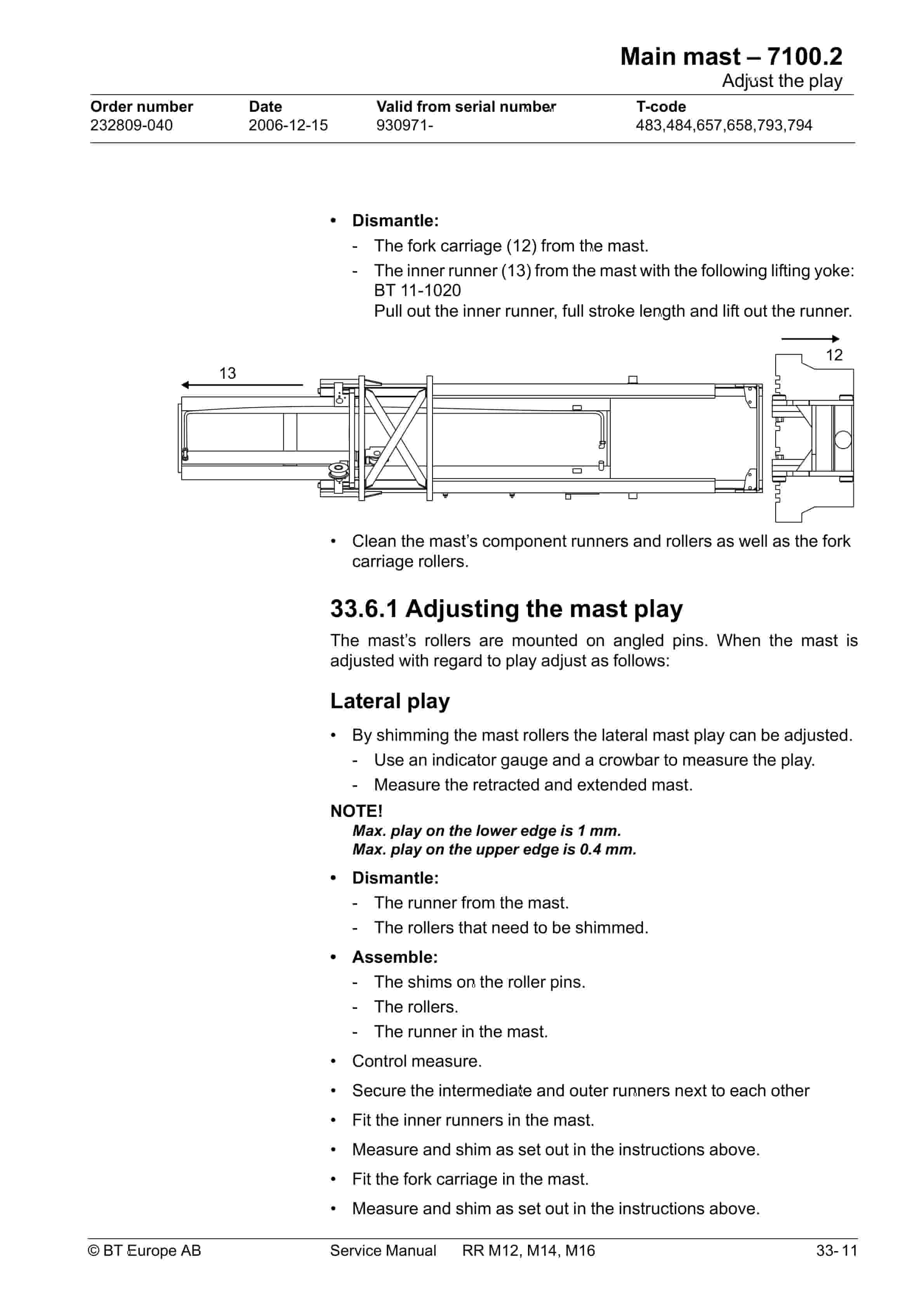
- 34.6. Adjust the play
- 34.6.1. Adjusting the mast play
- 34.6.2. Radial play
- 34.7. Assembling
- 34.8. Problem with the mast rollers
- 34.9. Adjusting the distance between the forks and floor
- 35. Main lift chain system – 7120
- 35.1. General
- 35.2. Checking the chain setting
- 35.3. Chain inspection
- 35.3.1. Noise
- 35.3.2. Surface rust
- 35.3.3. Rusty links
- 35.3.4. Stiff links
- 35.3.5. Bolt rotation
- 35.3.6. Loose bolts
- 35.3.7. Outline wear
- 35.3.8. Stretching
- 35.3.9. Damage
- 35.3.10. Damaged discs
- 35.3.11. Damaged bolts
- 35.3.12. Dirty chain
- 35.4. Cleaning
- 35.5. Lubrication
- 36. Lifting devices – 7400
- 36.1. General
- 36.1.1. Inspection intervals
- 36.1.2. Inspection
- 36.1.3. Surface cracks
- 36.1.4. Difference in height of fork tips
- 36.1.5. Positioning lock
Related products
-
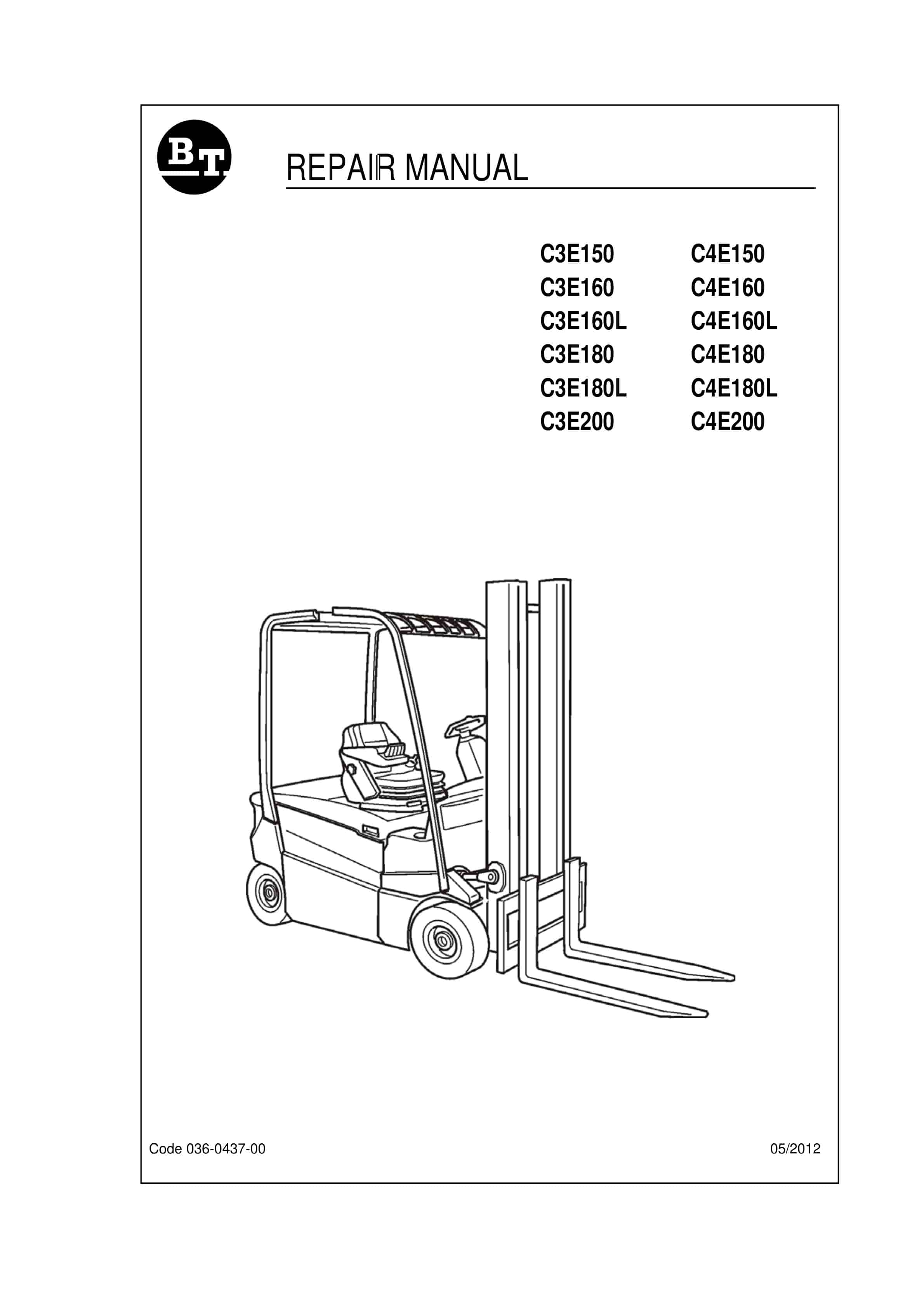
BT C3E150 to C4E200 Repair Manual 036-0437-00
$30.00 Add to cart -
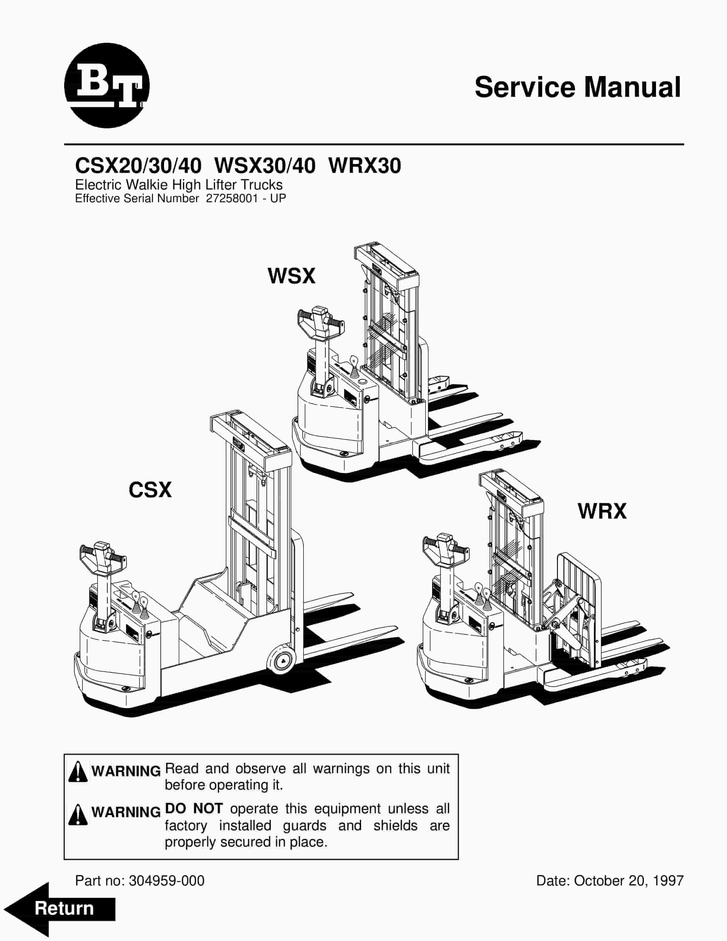
BT CSX20, CSX30, CSX40, WSX30, WSX40, WRX30 Electric Walkie High Lifter Truck Service Manual 304959-000
$30.00 Add to cart -
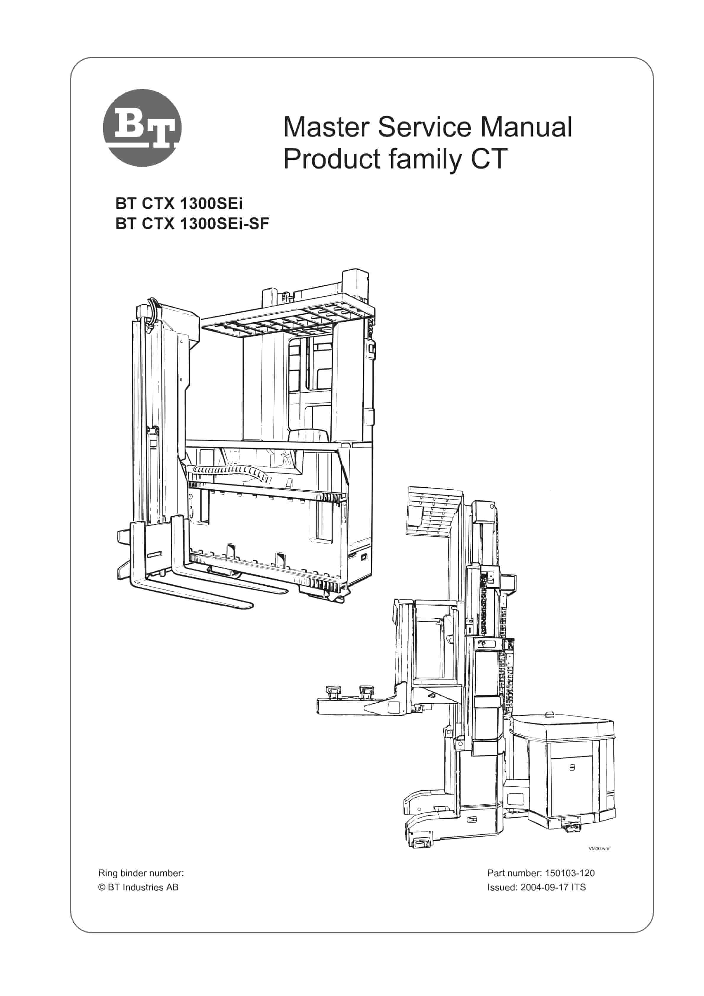
BT CTX 1300SEi, CTX 1300SEi SF Service Manual 150103-120
$30.00 Add to cart -
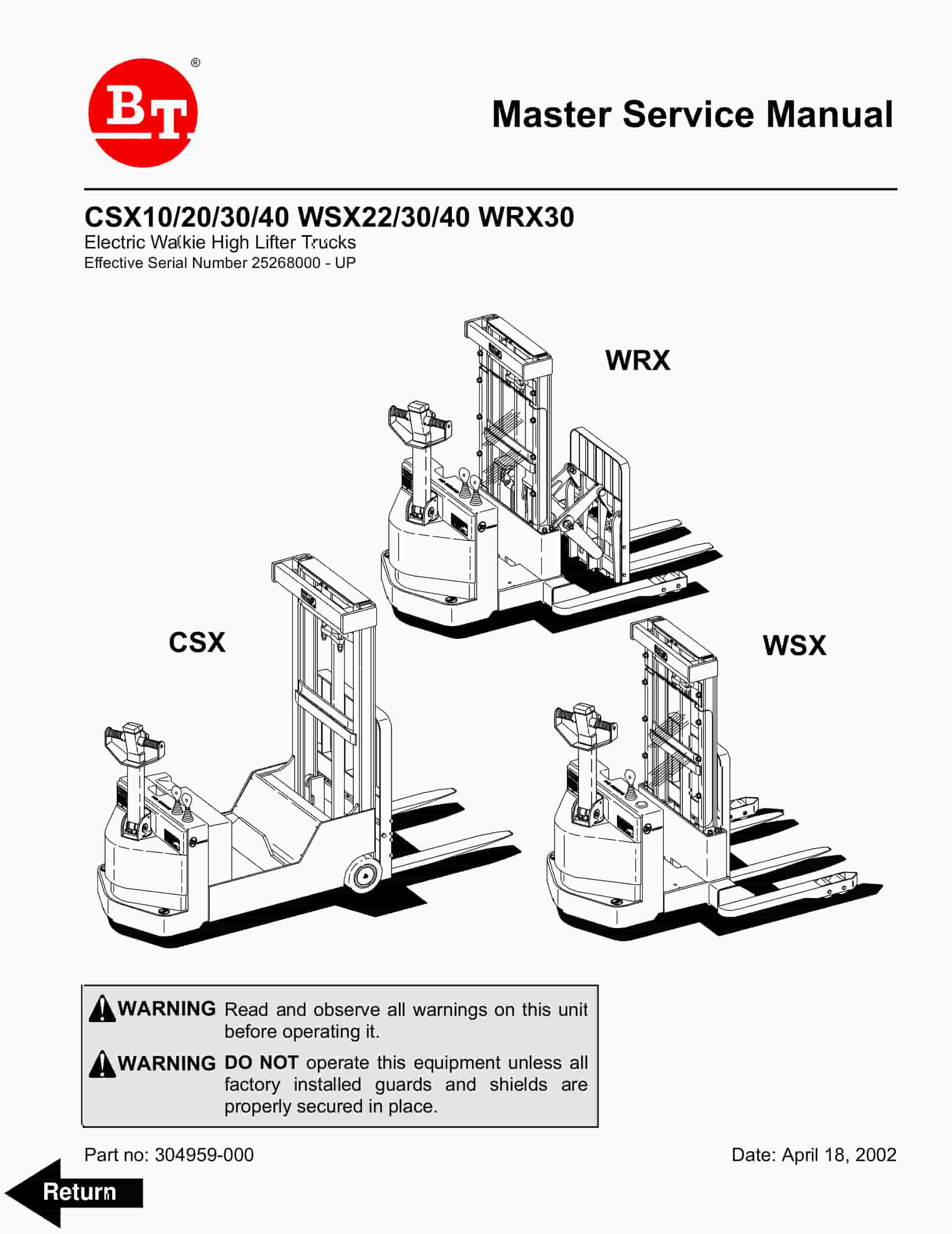
BT CSX10, CSX20, CSX30, CSX40, WSX22, WSX30, WSX40, WRX30 Electric Walkie High Lifter Truck Service Manual 304959-000
$30.00 Add to cart -
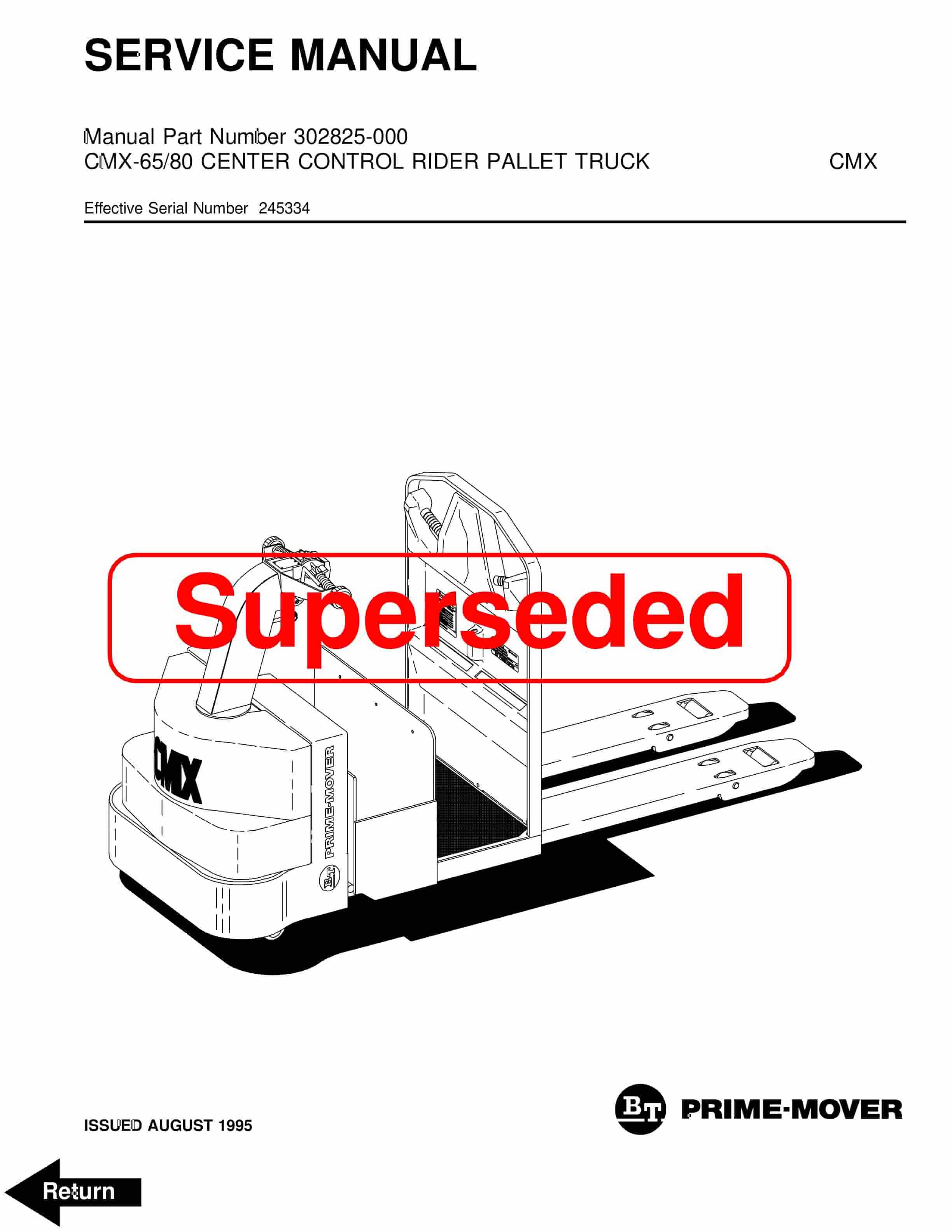
BT CMX-65, CMX-80 Center Control Riding Pallet Truck Service Manual 302825-000
$30.00 Add to cart


