


BT WSX-20, WSX-25 Electric Walkie Adjustable Straddle Stacker Service Manual 304944-000
$30.00
- Type Of Manual: Service Manual
- Manual ID: 304944-000
- : Service Manual PDF
- Number of Pages: 114
- Size: 1.7MB
- Format: PDF
Product details
-
Model List:
- WSX-20, WSX-25 Electric Walkie Adjustable Straddle Stacker
- 1. Front Cover
- 2. BT Standard Codes
- 2.1. Worksheet standard
- 2.2. C-Code List
- 3. Warning Symbols
- 3.1. Warning Levels
- 3.1.1. WARNING
- 3.1.2. CAUTION
- 4. Prohibitory Symbols
- 4.1. NO SMOKING
- 4.2. OPEN FLAMES PROHIBITED
- 4.3. GENERAL PROHIBITION
- 4.4. Ordinance Symbols
- 4.4.1. SAFETY SHOES
- 4.4.2. PROTECTIVE GLASSES
- 5. Introduction, service manual
- 6. Contents, Section M
- 6.1. Machine Information
- 7. General product information
- 7.1. Valid from machine number 270001-
- 7.2. Presentation of the WSX20/25
- 7.2.1. Intended application of the truck
- 7.2.2. Forbidden application of the truck
- 7.2.3. Truck data
- 7.2.3.1. Truck type
- 7.2.3.2. WSX20/25
- 7.2.4. Truck dimensions
- 7.2.5. Truck data plate
- 7.3. Main components
- 7.3.1. Tiller arm The truck is to be controlled by th…
- 7.3.2. Type plate With type designation, manufacturin…
- 7.3.3. Hoods Removable which provides good accessibil…
- 7.3.4. Instrument (accessory) Combined hour meter/bat…
- 7.3.5. Hydraulic control For controlling lifting and …
- 7.3.6. Hydraulic unit Pump motor, pump, valves, and o…
- 7.3.7. Hydraulic valves The valves are located to pro…
- 7.3.8. Drive unit with brake Fixed drive unit with a …
- 7.3.9. Machine number The manufacturing number plate …
- 7.3.10. Electric panel Removable, which provides good…
- 7.3.11. Battery 24V with different Ah values. The tru…
- 7.3.12. Battery isolator/Recharging connector The bat…
- 7.3.13. Mast Covered by a finger protection which cov…
- 7.4. Warning and information signs
- 7.4.1. Hydraulic control Lifting
- 7.4.2. Signal/Horn
- 7.4.3. Direction Forward/Rearward
- 7.4.4. General warning /informations sign
- 7.4.5. Hydraulic control Lowering
- 7.4.6. Hydraulic oil level
- 7.4.7. Machine data plate
- 7.4.8. No Riding decal
- 7.4.9. Machine signs
- 7.4.10. Do not stand on the forks/Do not walk under li…
- 7.4.11. Lifting points
- 7.4.12. Pinch point
- 8. Inch (SAE) and Metric Fasteners
- 8.1. Introduction
- 8.2. Nomenclature, Threads
- 8.3. Strength Identification
- 8.4. Conversion of Metric and English Units
- 9. Technical service data
- 9.1. Valid from machine number 270001 –
- 10. Ordering Spare Parts
- 10.1. Locate the fault on the truck.
- 10.2. Find out the machine model and serial number.
- 10.3. Locate the page with the exploded diagram and f…
- 10.4. Locate the position number in the table. Select…
- 10.5. Note the part number.
- 10.6. Call the local BT dealer and state the part num…
- 11. Contents, Section P
- 11.1. Planned Maintenance
- 12. Introduction, Maintenance
- 12.1. Safe Jacking Procedure
- 13. Service schedule
- 13.1. Valid from machine number 270001 –
- 13.2. Preventive maintenance schedule
- 13.2.1. WORK REQUIRED
- 13.2.1.1. Interval in hours
- 13.2.1.2. Interval in Days/Weeks/Months
- 14. Lubrication chart
- 14.1. Valid from machine number 270001-
- 14.1.1. Service point
- 14.1.2. Interval/Running hours
- 14.1.3. Lubricant
- 15. Oil and grease specification
- 15.1. Valid from machine number 270001-
- 15.2. Approved oils and grease
- 15.2.1. Lubricant
- 15.2.2. Specification
- 15.2.3. Application area
- 15.2.4. > – 15C
- 15.2.5. < – 15C
- 16. Contents, Section S
- 16.1. Service Instructions
- 17. Support arm chassis
- 17.1. Valid from machine number 270001-
- 17.2. General
- 17.3. Main components
- 17.3.1. Description
- 17.4. Maintenance
- 17.5. Adjustment of the support arm width
- 17.5.1. Warning
- 17.6. Exchange of support arms
- 17.7. Transmission
- 17.7.1. Valid from machine number 270001-
- 17.7.2. General technical description
- 17.7.2.1. Technical data
- 17.7.2.1.1. Description
- 17.7.2.2. Gear components
- 17.7.2.2.1. Component
- 17.7.2.3. Special tools
- 17.7.3. Removing the gear from the truck
- 17.7.4. Change of seal on the drive shaft
- 17.7.5. Reconditioning of the gear
- 18. Electrical System
- 18.1. Valid from machine number 270001-
- 18.2. Electrical panel, components.
- 18.3. List of symbols.
- 18.3.1. Description
- 18.3.2. Function
- 18.3.3. Circuit diagram 1(3)
- 18.3.4. Circuit diagram 2(3)
- 18.3.5. Circuit diagram 3(3)
- 18.4. DESCRIPTION OF FUNCTION
- 18.4.1. General
- 18.4.2. Adjustable settings
- 18.4.3. References
- 18.4.4. Key switch S17 in the ON position
- 18.4.5. The operating arm in drive position, S10, bra…
- 18.4.6. Driving, fork direction
- 18.4.7. Driving, steer wheel direction
- 18.4.8. Reversing/motor brake fork direction to steer…
- 18.4.9. Reversing/motor brake steer wheel direction t…
- 18.4.10. Reverser switch
- 18.4.11. Lifting the forks
- 18.4.12. Horn
- 18.5. Options
- 18.5.1. Electrical lowering of the forks
- 18.6. Wire Coupler
- 18.6.1. Electrical wire coupler
- 19. Battery Controller / Hourmeter / Lift Interrupt
- 19.1. General Information
- 19.2. Electrical
- 19.2.1. Voltage
- 19.2.1.1. The Contact Voltage and Current Ratings for…
- 19.2.1.2. Memory Retention
- 19.3. Battery Controller (BC)
- 19.3.1. General Information
- 19.3.1.1. Discharge Adjustment
- 19.3.1.1.1. Battery Ah
- 19.3.1.1.2. SETTING
- 19.3.1.1.3. SETTING
- 19.3.1.1.4. PIN NO
- 19.3.1.1.5. FUNCTION
- 19.3.2. Reset
- 19.3.3. Key Switch
- 19.3.4. Hourmeter
- 19.4. Troubleshooting
- 19.4.1. Battery Discharge Indicator (BDI)
- 19.4.1.1. No Reset
- 19.4.1.2. Reset After Break in Power
- 19.4.1.3. No Discharge, Gauge Does Not Run Down
- 19.4.1.4. No Lockout
- 19.4.1.5. No Lift
- 19.4.1.6. Early Lockout
- 19.4.1.7. LEDs Do Not Light
- 19.4.2. Hourmeter
- 19.4.2.1. No Display
- 19.4.2.2. Hourmeter Glass Icon Does Not Flash
- 19.4.2.3. Hourmeter Glass Icon Always Flashes
- 20. Transistor Controller
- 20.1. Valid from machine number 270001-
- 20.2. Motor circuit
- 20.2.1. Terminal
- 20.2.2. Connecting
- 20.3. Control circuit
- 20.3.1. Connecting
- 20.4. Technical specification
- 20.4.1. PARAMETER
- 20.4.2. STD SETTING
- 20.4.3. DESCRIPTION
- 20.5. Adjustment panel
- 20.5.1. Adjustable Potentiometers
- 20.5.2. Connection of hand held terminal
- 20.5.3. Status LED
- 20.6. Maintenance
- 20.6.1. Safety
- 20.6.2. Cleaning
- 20.6.2.1. Remove power by disconnecting the battery.
- 20.6.2.2. Discharge the capacitors in the controller, by …
- 20.6.2.3. Remove all dirt or corrosion from the bus bar a…
- 20.6.2.4. Make sure the connections to the bus bars are t…
- 20.7. Diagnostics and troubleshooting
- 20.7.1. LED CODE
- 20.7.2. TERMINAL LCD DISPLAY
- 20.7.3. EXPLANATION
- 20.7.4. POSSIBLE CAUSE
- 21. PCB Card
- 21.1. Valid from machine number 270001-
- 21.2. The PCB
- 21.3. Connectors and adjustments
- 21.3.1. Position
- 21.3.2. Connection/Adjustment
- 21.4. Terminals and LEDs
- 21.4.1. Terminal No
- 21.4.2. Connection
- 21.4.3. Function
- 22. Hydraulic system, mechanical lowering
- 22.1. Valid from machine number 270001-
- 22.2. General
- 22.3. Description of function
- 22.3.1. Hydraulic diagram and components
- 22.3.2. Main components
- 22.3.2.1. Description
- 22.3.3. Description
- 22.3.3.1. Lift
- 22.3.3.2. Lower
- 22.3.3.3. Operating pressure
- 22.3.3.3.1. WSX20 2090 psi
- 22.3.3.3.2. WSX25 2610 psi
- 22.3.3.4. Relief valve
- 22.3.3.4.1. WSX20 2300 psi
- 22.3.3.4.2. WSX25 2870 psi
- 23. Hydraulic system, electrical lowering
- 23.1. Valid from machine number 270001-
- 23.2. General
- 23.3. Description of function
- 23.3.1. Hydraulic diagram and components
- 23.3.2. Main components
- 23.3.2.1. Description
- 23.3.3. Description
- 23.3.3.1. Lift
- 23.3.3.2. Lower
- 23.3.3.3. Lower, electrical
- 23.3.3.4. Operating pressure
- 23.3.3.4.1. WSX20 2090 psi
- 23.3.3.4.2. WSX25 2610 psi
- 23.3.3.5. Relief valve
- 23.3.3.5.1. WSX20 2300 psi
- 23.3.3.5.2. WSX25 2870 psi
- 24. Back Cover
Related products
-
BT CBE 25, CBE 30, CBE 30L, CBE 35 Service Manual 036-0402-02
$30.00 Add to cart -
BT ERGOMOVER Service Manual 180731-040
$30.00 Add to cart -
BT CMX-65, CMX-80 Center Control Riding Pallet Truck Service Manual 302825-000
$30.00 Add to cart -
BT CBE 25, CBE 30, CBE 30L, CBE 35 Service Manual 036-0409-02
$30.00 Add to cart -
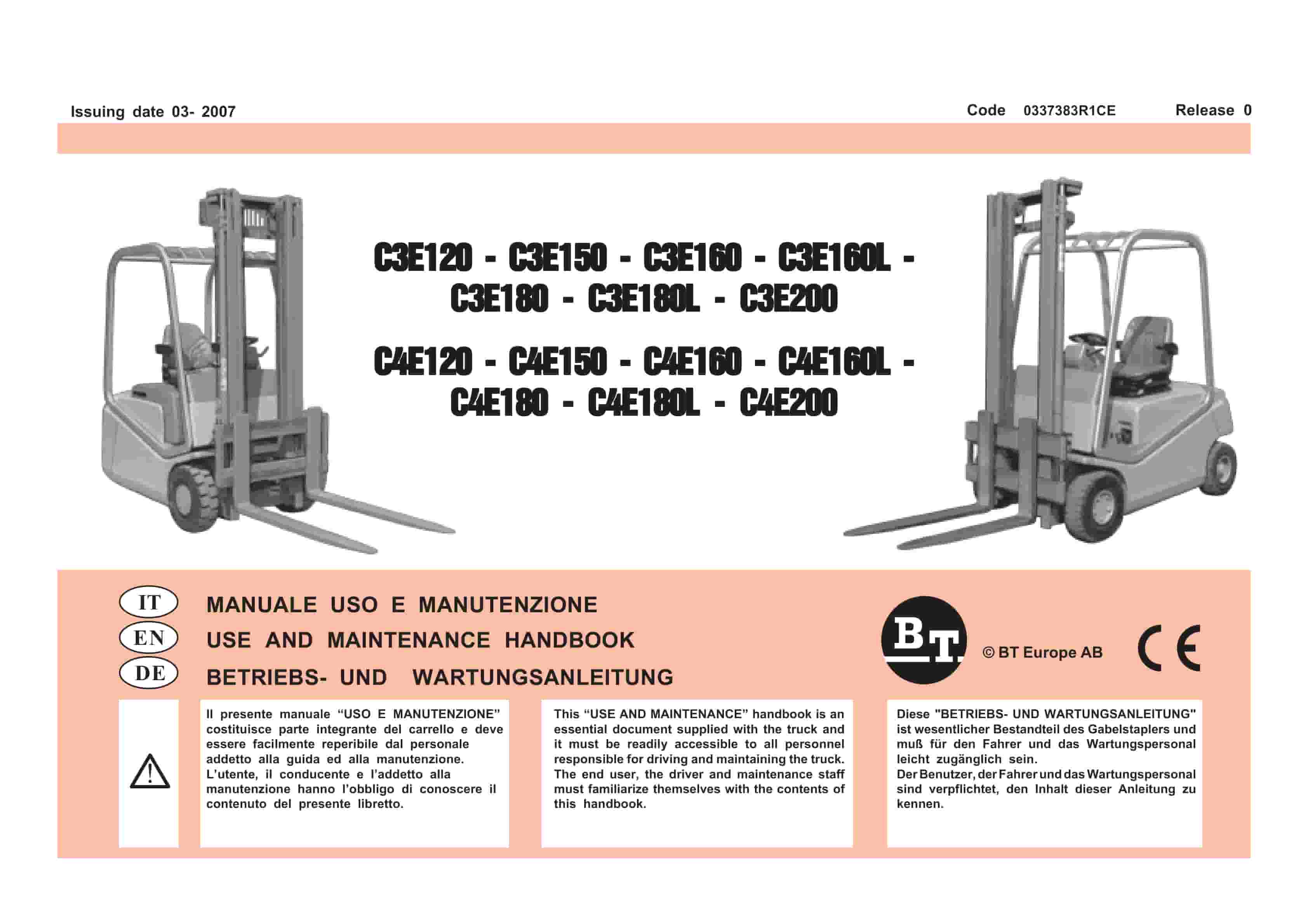
BT C3E120 to C4E200 Use And Maintenance Handbook 0337383R1CE
$30.00 Add to cart