

Caterpillar 6018, 6018 FS Hydraulic Shovel Operation And Maintenance Manual BI015192
$30.00
- Type Of Manual: Operation And Maintenance Manual
- Manual ID: BI015192
- Number of Pages: 328
- Size: 11.8MB
- Format: PDF
Product details
-
Model List:
- 6018, 6018 FS Hydraulic Shovel
- 1. BA RH90C(3 847 017.00)-EN.pdf
- 1.1. TITLEPAGE
- 1.2. INTRODUCTION
- 1.2.1. PREFACE
- 1.2.1.1. About this Operation and Maintenance Manual
- 1.2.1.2. Further machine documentation
- 1.2.2. WARRANTY
- 1.2.3. FUNDAMENTAL SAFETY INSTRUCTIONS
- 1.2.3.1. Warnings and symbols
- 1.2.4. DESIGNATED USE
- 1.2.5. ORGANIZATIONAL MEASURES
- 1.2.5.1. Selection and qualification of personnel basic responsibilities
- 1.2.5.2. Safety instructions governing specific operational phases
- 1.2.5.3. Special work in conjunction with utilization of the machine and maintenance and repairs as well as troubleshooting during work disposal of parts and consumables
- 1.2.5.4. Warning of special dangers
- 1.2.5.5. Gas, dust, steam and smoke
- 1.2.5.6. Hydraulic equipment
- 1.2.6. INTRODUCTION, FIRE AND EXPLOSION HAZARD
- 1.3. OPERATION
- 1.3.1. OPERATION – SAFETY INSTRUCTIONS
- 1.3.1.1. Operating Instructions, where to store it in the drivers cab
- 1.3.2. OPERATION, FIRE AND EXPLOSION HAZARD
- 1.3.3. DESCRIPTION OF THE EXCAVATOR
- 1.3.3.1. Excavator layout
- 1.3.3.2. Undercarriage
- 1.3.3.3. Superstructure
- 1.3.3.4. Hydraulic system
- 1.3.3.5. Pump Managing System (PMS)
- 1.3.3.6. Stored Program Control (SPC)
- 1.3.3.7. Central Management System (CMS)
- 1.3.3.8. Demand control / Zero-flow regulation
- 1.3.3.9. Automatic engine speed reduction
- 1.3.3.10. Board-Control-System (BCS)
- 1.3.3.11. Electrical system
- 1.3.3.12. Signs and labels
- 1.3.3.13. Entering and leaving the machine, Safety instructions
- 1.3.3.14. Access ladder lighting
- 1.3.3.15. Swinging ladder
- 1.3.3.16. Switching the cab interior lighting on and off
- 1.3.3.17. Switching the servicing lighting on and off
- 1.3.3.18. EMERGENCY STOP switch
- 1.3.3.19. Drivers seat
- 1.3.3.20. Trainers / instructors seat
- 1.3.3.21. Windscreen washer
- 1.3.3.22. Fire extinguisher
- 1.3.3.23. Automatic fire-extinguishing system (optional)
- 1.3.3.24. Harness (optional)
- 1.3.4. MONITORING, WARNING AND CONTROL ELEMENTS
- 1.3.5. PUTTING THE MACHINE INTO OPERATION
- 1.3.5.1. Refuelling
- 1.3.5.2. Service station (tanklift)
- 1.3.5.3. Switching the electrical system on and off
- 1.3.5.4. Preheating system for engine and hydraulic oil (optional)
- 1.3.5.5. Fuel preheating system (optional)
- 1.3.6. STARTING AND STOPPING THE ENGINES
- 1.3.6.1. Starting the engines
- 1.3.6.2. Starting the engines at low temperatures
- 1.3.7. AIR CONDITIONER (OPTION)
- 1.3.7.1. Back-up heating (option)
- 1.3.8. MAXIMUM MACHINE INCLINATIONS, INFORMATION
- 1.3.9. DRIVING, SAFETY INSTRUCTIONS
- 1.3.10. TRAVELLING
- 1.3.10.1. Superstructure basic position
- 1.3.10.2. Travelling forwards/backwards
- 1.3.10.3. Locking the superstructure
- 1.3.10.4. Track parking brake
- 1.3.11. TRANSPORTING THE MACHINE
- 1.3.11.1. Transport – Safety instructions
- 1.3.12. WORKING OPERATION – SAFETY INSTRUCTIONS
- 1.3.12.1. Running-in instructions for hydraulic cylinders
- 1.3.12.2. Warming-up phase for the hydraulic system
- 1.3.12.3. Avoid extreme positions of the working equipment
- 1.3.13. WORKING OPERATION
- 1.3.13.1. Before starting work
- 1.3.13.2. Switching on the electronic excavator control
- 1.3.13.3. Swinging the superstructure
- 1.3.13.4. Braking the superstructure
- 1.3.13.5. Working movements
- 1.3.13.6. After daily operation
- 1.3.14. ASSEMBLING WORKING EQUIPMENT – SAFETY INSTRUCTIONS
- 1.3.14.1. Securing the machine
- 1.3.15. CORROSION PROTECTION FOR PINS AND BEARINGS (BUSHINGS AND HUBS)
- 1.4. INSPECTION AND SERVICING
- 1.4.1. INSPECTION AND SERVICING – SAFETY INSTRUCTIONS
- 1.4.2. INSPECTION AND SERVICING WORK, FIRE AND EXPLOSION HAZARD
- 1.4.3. INSPECTION AND SERVICING PLANS – INSTRUCTIONS
- 1.4.3.1. Plan V
- 1.4.3.2. Plan N
- 1.4.3.3. Plan T and W
- 1.4.3.4. Plan A E
- 1.4.4. LUBRICATING CHART GREASE
- 1.4.4.1. Lubricating chart Grease (legend)
- 1.4.4.2. Filling quantities – Grease
- 1.4.5. INSPECTION PLAN – OIL
- 1.4.5.1. Inspection plan Oil (legend)
- 1.4.5.2. Filling quantities – oil
- 1.4.5.3. Filling quantities – other
- 1.4.6. LUBRICANTS, CONSUMABLES
- 1.4.6.1. Notes on the selection of oils and greases
- 1.4.6.2. Avoid mixing of different hydraulic fluids
- 1.4.6.3. Oils for combustion engines
- 1.4.6.4. II. Fluid for hydraulic system
- 1.4.6.5. III.a Oils for pump distribution gearboxes and travel gearboxes
- 1.4.6.6. III.b Oils for swing gearboxes
- 1.4.6.7. Grease for bearings, swing rings and track system (Central lubrication system)
- 1.4.6.8. Greases for idlers, track rollers and support rollers (Lifetime lubrication)
- 1.4.6.9. Coolant for use on all combustion engines
- 1.4.7. SERVICING WORK
- 1.4.7.1. Hose line for oil and cooling liquid changes
- 1.4.8. ENGINE
- 1.4.8.1. Engine – Safety instructions
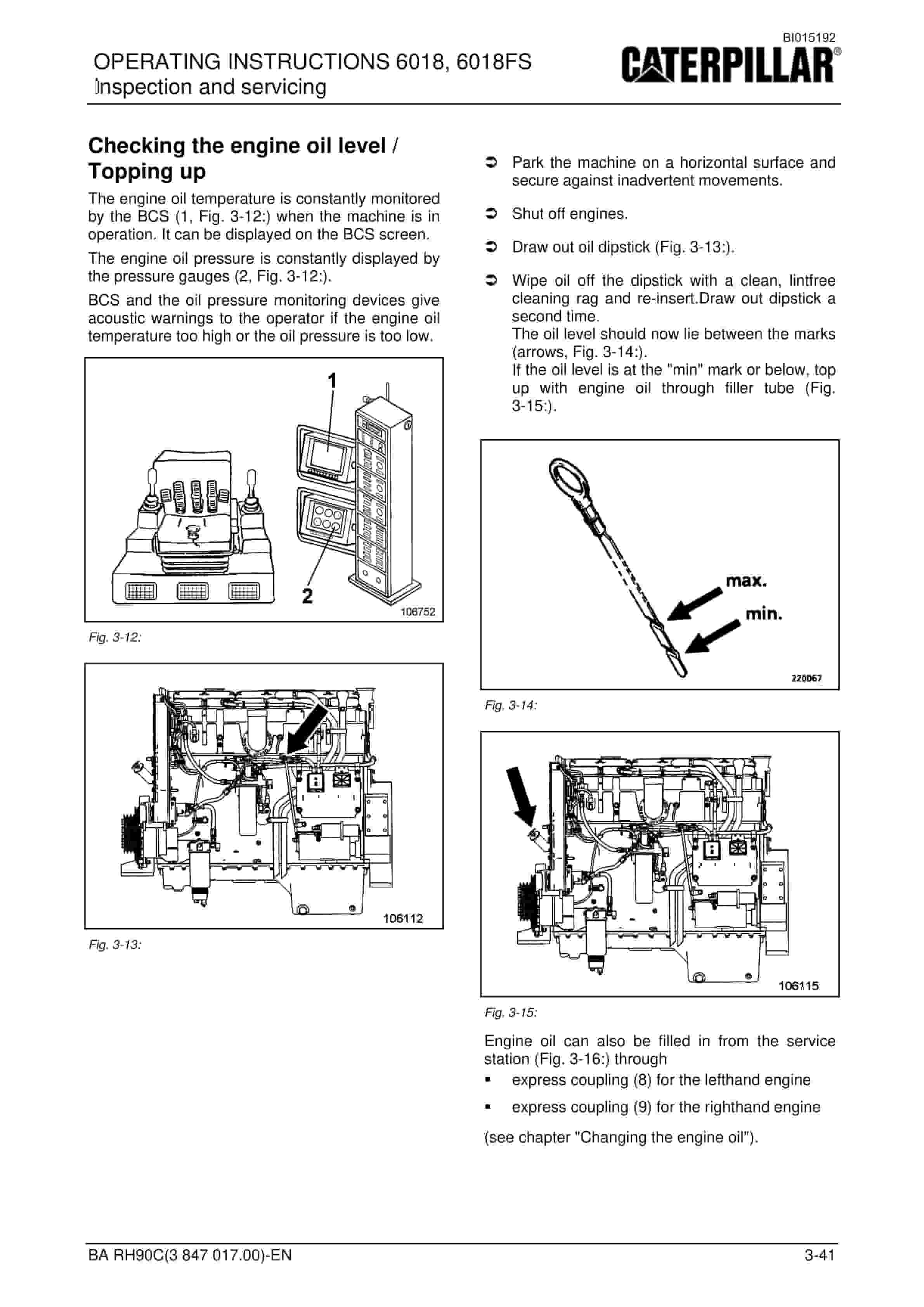
- 1.4.8.2. Checking the engine oil level / Topping up
- 1.4.8.3. Changing the engine oil
- 1.4.8.4. Replacing the oil filters
- 1.4.8.5. Cold-starting fluid (ether) – Replacing the pressure vessel
- 1.4.9. COOLING SYSTEM
- 1.4.9.1. Radiators
- 1.4.9.2. Cooling liquid change
- 1.4.10. AIR-INTAKE SYSTEM
- 1.4.10.1. Dust trap, cleaning
- 1.4.10.2. Main filter elements
- 1.4.10.3. Safety filter element
- 1.4.10.4. Air-intake lines
- 1.4.11. FUEL SYSTEM
- 1.4.11.1. Fuel system – Safety instructions
- 1.4.11.2. Replacing the fuel filter
- 1.4.11.3. Venting the fuel system
- 1.4.11.4. Cleaning the fuel tanks
- 1.4.11.5. Water trap (option)
- 1.4.12. ELECTRICAL SYSTEM
- 1.4.12.1. Electrical system – Safety instructions
- 1.4.12.2. Alternator – Instructions
- 1.4.12.3. Battery
- 1.4.12.4. Switchgear cabinet, filter element
- 1.4.12.5. Floodlight projector, replacing the lamp
- 1.4.12.6. Lighting systems in LED technonogy, instructions
- 1.4.13. HYDRAULIC SYSTEM
- 1.4.13.1. Hydraulic system – Safety instructions
- 1.4.13.2. Depressurizing the hydraulic system
- 1.4.13.3. Checking the hydraulic oil level
- 1.4.13.4. Changing the hydraulic oil return-flow (hydraulic oil reservoir)
- 1.4.13.5. Bypass valves (hydraulic oil reservoir)
- 1.4.13.6. Breather filter
- 1.4.13.7. High-pressure filter for working hydraulics
- 1.4.13.8. High-pressure filters for the servo circuit
- 1.4.13.9. Filter (control circuit)
- 1.4.13.10. Changing the hydraulic oil
- 1.4.13.11. Venting the hydraulic system
- 1.4.13.12. Cleaning the hydraulic oil cooler
- 1.4.13.13. Electronic excavator control
- 1.4.13.14. Pressure accumulator – Emergency lowering
- 1.4.14. PUMP GEARBOX
- 1.4.14.1. Checking the gearbox oil level / Topping up with oil
- 1.4.14.2. Changing the gearbox oil
- 1.4.14.3. Gearbox venting
- 1.4.15. SWING GEARBOX
- 1.4.15.1. Gearbox – Checking the oil level / Topping up with oil
- 1.4.15.2. Changing the gearbox oil
- 1.4.15.3. Gearbox venting
- 1.4.16. TRAVEL GEARBOX
- 1.4.16.1. Travel gearbox – Checking the oil level / Topping up with oil
- 1.4.16.2. Travel gearbox – Changing oil
- 1.4.16.3. Travel gearbox, breather filter
- 1.4.17. CRAWLER TRACKS
- 1.4.17.1. Track roller, Support roller
- 1.4.17.2. Track tensioner
- 1.4.17.3. Pressure-accumulator inspection regulations
- 1.4.17.4. Checking the gas charging pressure in the pressure accumulator
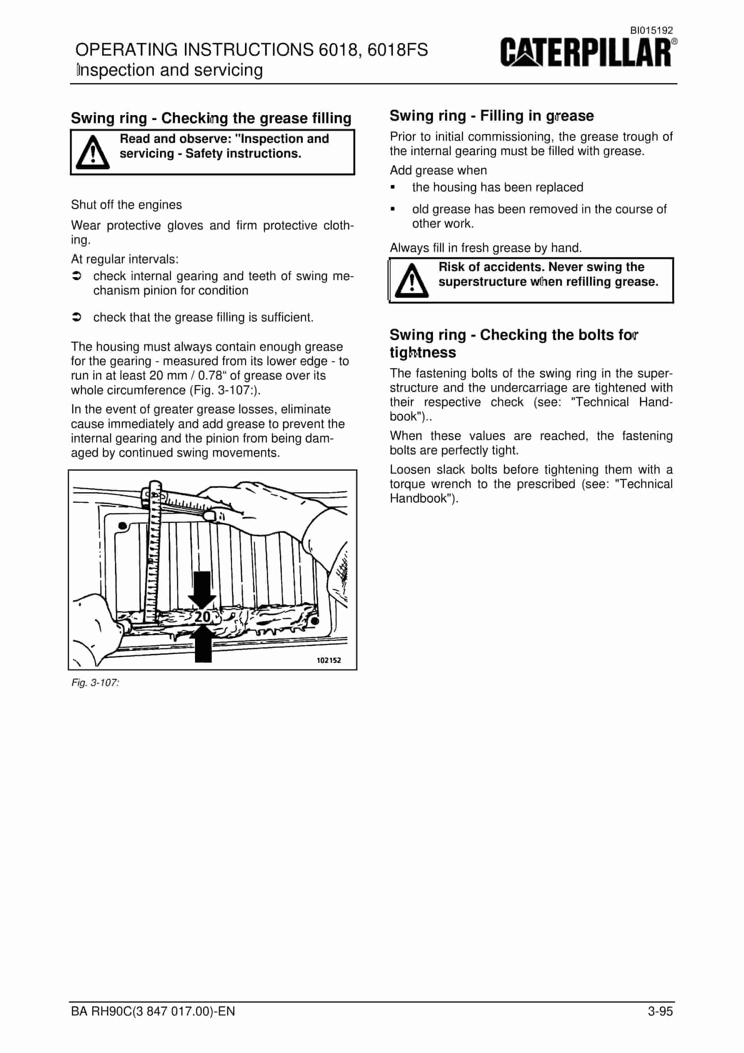
- 1.4.18. SWING RING
- 1.4.18.1. Swing ring – Instructions
- 1.4.18.2. Bearing races
- 1.4.19. CENTRAL LUBRICATING SYSTEM, STANDARD
- 1.4.19.1. Design
- 1.4.19.2. Function
- 1.4.19.3. Replacing the grease container
- 1.4.19.4. Filling up the grease container
- 1.4.19.5. Checking the greasing pressure
- 1.4.19.6. Unblocking a grease line
- 1.4.19.7. Oilfilter (hydraulic circuit grease pump) )
- 1.4.19.8. Grease filter (Filling the grease container)
- 1.4.19.9. Grease filter (Grease lines)
- 1.4.20. OTHER MAINTENANCE
- 1.4.20.1. Engine
- 1.4.20.2. Heating and air conditioning
- 1.4.21. HYDRAULIC LADDER
- 1.4.21.1. Pressure-accumulator inspection regulations
- 1.4.22. PUTTING THE EXCAVATOR OUT OF OPERATION AND RECOMMISSIONING
- 1.4.22.1. Putting the excavator out of operation
- 1.4.22.2. Battery storage
- 1.4.22.3. Recommissioning
- 1.5. REPAIR WORK
- 1.5.1. REPAIR WORK – SAFETY INSTRUCTIONS
- 1.5.2. REPAIR WORK, FIRE AND EXPLOSION HAZARD
- 1.5.3. ENGINE, REPAIR WORK
- 1.5.4. ELECTRICAL SYSTEM
- 1.5.4.1. Assisted starting (with jumper cables) Safety instructions
- 1.5.4.2. Assisted starting (with jumper cables)
- 1.5.4.3. Starting the engine with jumper cables (external batteries
- 1.5.5. HYDRAULIC SYSTEM
- 1.5.5.1. Repair instructions
- 1.5.5.2. Hydraulic hoses Instructions
- 1.5.6. PRESSURE ACCUMULATORS – SAFETY INSTRUCTIONS
- 1.5.7. WELDING AND FLAME CUTTING WORKS – SAFETY INSTRUCTIONS
- 1.5.8. DISPOSAL AT THE END OF THE SERVICE LIFE
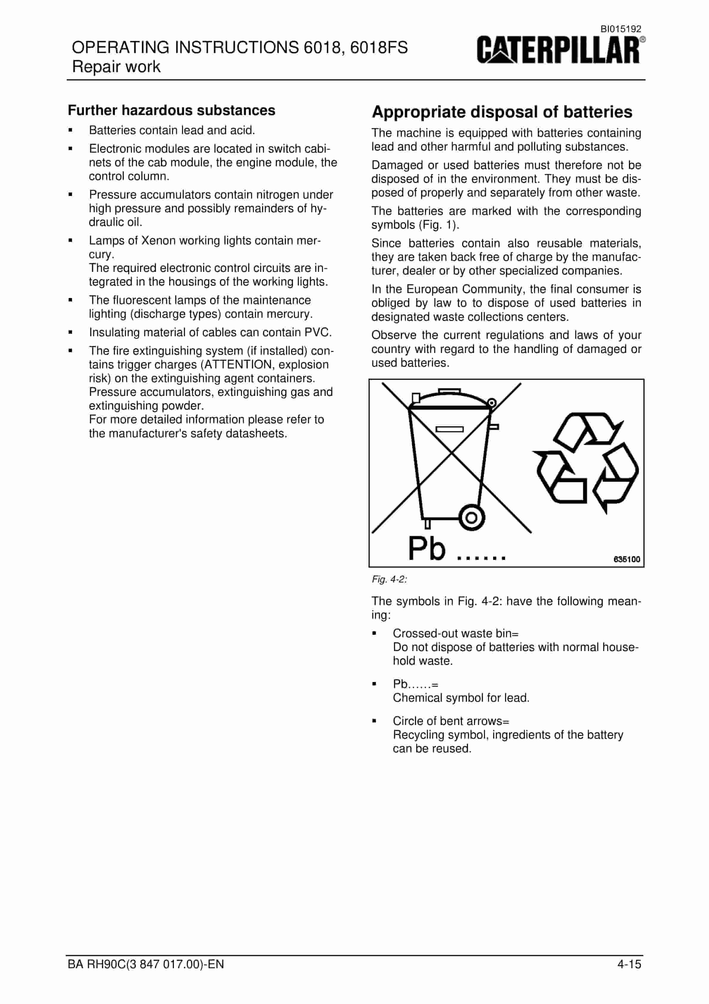
- 1.5.8.1. Appropriate disposal of batteries
- 1.6. ANNEX
- 1.6.1. TROUBLESHOOTING
- 1.6.1.1. Instructions on troubleshooting
- 1.6.1.2. Layout of the fault table
- 1.6.2. FAULT TABLES
- 1.6.2.1. Combustion engine – Fault table
- 1.6.2.2. Working hydraulics Fault table
- 1.6.2.3. Track drive Fault table
- 1.6.2.4. Swing mechnism Fault table
- 1.6.2.5. Central lubricating system Fault table
- 1.6.3. HYDRAULIC CIRCUIT DIAGRAM
- 1.6.4. ABBREVIATIONS
- 1.6.4.1. ABBREVIATIONS
- 1.6.5. TECHNICAL DATA
- 1.6.5.1. Product Specification Sheet
- 1.7. INDEX
- 2. BA_BCS_6018_3847018_en.pdf
- 2.1. TITLEPAGE
- 2.1.1. DESCRIPTION
- 2.1.1.1. Functions
- 2.1.1.2. Components
- 2.1.2. DISPLAYS USING BCS
- 2.1.2.1. Display and keyboard
- 2.1.2.2. Instruments
- 2.1.2.3. Service menu
- 2.1.2.4. Fault reports
- 2.1.2.5. Service data fault storage print-out or transfer into Buffer
- 2.1.3. APPENDIX
- 2.1.3.1. Print-out
- 3. _3847003en.pdf
- 3.1. DECK-EN
- 3.2. Inhalt-en
- 3.3. Text-EN
- 3.3.1. Safety instructions
- 3.3.2. Notes on the selection of oils and greases
- 3.3.3. Caterpillar Global Mining HMS oils and greases
- 3.3.4. Alternative oils and greases
- 3.3.5. Why carry out oil analyses
- 3.3.5.1. Oil samples are taken at the following places
- 3.3.6. Prerequisites for valid oil samples
- 3.3.6.1. Analyses-Sets
- 3.3.7. Taking oil samples
- 3.3.7.1. Sampling from assemblies equipped with sampling valve
- 3.3.7.2. Sampling from assemblies without sampling valve
- 3.3.8. Interpreting the results of the oil analysis
- 3.3.8.1. A typical laboratory report
- 3.3.8.2. Typical laboratory report
- 3.3.9. Typical wear limits
- 3.3.9.1. For hydraulic oil in the 6015, 6018, 6030, 6040 machines
- 3.3.9.2. For hydraulic oil in 6050, 6060, 6090 machines
- 3.3.9.3. For oil in the pump transfer gearboxes of the 6015, 6018, 6030
- 3.3.9.4. For oil in the pump transfer gearboxes of the 6040, 6050, 6060
- 3.3.9.5. For oil in the pump transfer gearboxes of the 6090
- 3.3.9.6. For oil in the swing gearboxes of the 6015 – 6090
- 3.3.9.7. For oil in the travel gearboxes of the 6015, 6018
- 3.3.9.8. For oil in the travel gearboxes of the 6030, 6040, 6060
- 3.3.9.9. For oil in the travel gearboxes of the 6050, 6090
- 3.4. rueckseite_mit_cat_logo_en
Related products
-
Caterpillar CM220 Continuous Miner Operation And Maintenance Manual A6474X307
$30.00 Add to cart -
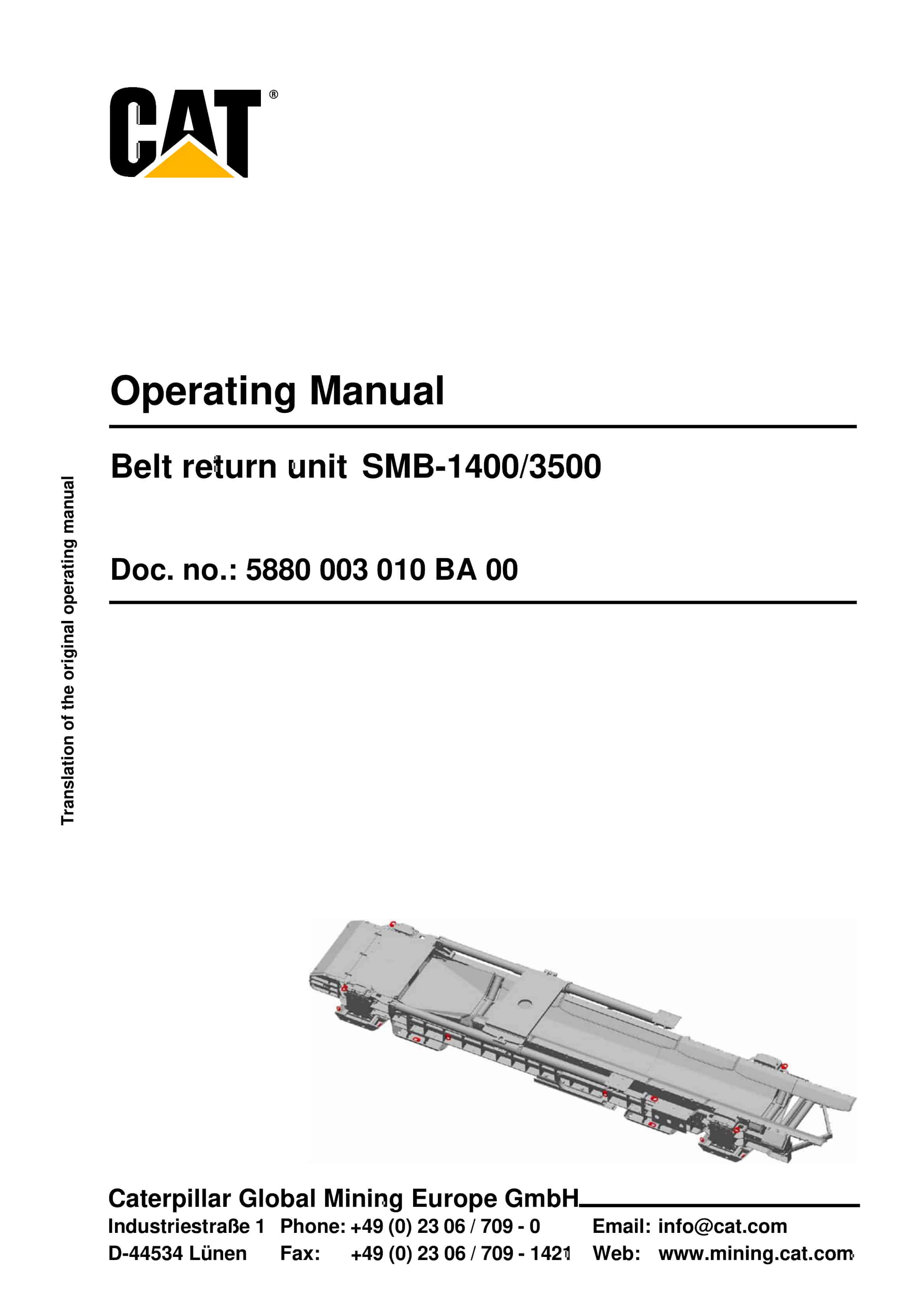
Caterpillar Belt Return Unit SMB-1400-3500 Operating Manual 5880 003 010 BA 00
$30.00 Add to cart -
Caterpillar Cervis Control System Operation Manual BI001580
$30.00 Add to cart -
Caterpillar CM345 Continuous Miner Operation And Maintenance Manual BI001593-02
$30.00 Add to cart -
Caterpillar CM345 Continuous Miner Operation And Maintenance Manual BI001589
$30.00 Add to cart


