


BT RC-30B, RC-40B, RC-50B Electric Stand-Up Rider Counterbalanced Truck Repair Manual 301981-000
$30.00
- Type Of Manual: Repair Manual
- Manual ID: 301981-000
- : Service Manual PDF
- Number of Pages: 238
- Size: 16.8MB
- Format: PDF
Category: BT Service Manual PDF
-
Model List:
- RC-30B, RC-40B, RC-50B Electric Stand-Up Rider Counterbalanced Truck
- 1. Front Cover
- 2. Contents
- 2.1. Wiring Diagrams
- 2.2. Hydraulic Schematics
- 2.3. General Information
- 2.4. Troubleshooting
- 2.5. Maintenance
- 2.6. Specifications Tables
- 2.7. Torque Specifications
- 3. Introduction
- 3.1. The Service Manual
- 3.2. How to Use this Manual
- 3.3. The Equipment
- 4. Safety Precautions – Maintenance Repair
- 5. Specifications Tables
- 5.1. General
- 5.2. Capacities
- 5.3. Steering System
- 5.4. Batteries
- 5.5. Travel Speeds Current Draw
- 5.6. Lifting Speeds
- 5.7. Lift Tilt System
- 6. Torque Specifications
- 7. Contents
- 7.1. Introduction
- 7.2. Maintenance Procedures
- 8. Introduction
- 8.1. General
- 8.2. Towing a Disabled Lift Truck
- 8.3. Lifting a Disabled Lift Truck
- 8.4. Putting the Lift Truck on Blocks
- 8.5. Scheduled Maintenance and Inspections
- 8.6. Scheduled Maintenance Inspections Table
- 9. Maintenance Procedures Every 8 Hours or Daily
- 9.1. General
- 9.1.1. SRO Circuit
- 9.1.2. General Functions
- 9.2. Battery
- 9.2.1. Charging the Battery
- 9.2.2. Changing the Battery
- 9.3. Battery Connector
- 9.3.1. Inspection
- 9.4. Battery Gates
- 9.4.1. Inspection
- 9.5. Upright
- 9.6. Hydraulic System
- 9.6.1. Checking for Leaks
- 9.7. Drive Unit
- 9.7.1. Checking Operation
- 9.7.2. Inspection
- 9.8. Wheels Tires
- 9.8.1. Inspection
- 9.8.2. Drive Wheel – Removal Installation
- 9.8.3. Steer Wheel – Removal Installation
- 9.8.4. Changing Tires
- 9.9. Brake Pedal
- 9.9.1. Inspect Lubricate
- 9.10. Brake Switch
- 9.10.1. Check for Operation
- 9.10.2. Check Operation
- 9.11. Controls/Horn
- 9.11.1. Check Operation
- 9.12. Steering System
- 9.12.1. Check Operation
- 9.12.2. Inspect
- 9.12.3. Inspect
- 10. Maintenance Procedures Every 40 Hours or 5 Days
- 10.1. Battery
- 10.1.1. Cleanliness
- 10.1.2. Water Level
- 10.2. Lift Chains
- 10.2.1. Inspect
- 10.3. Hydraulic System
- 10.3.1. Check Oil Level
- 11. Maintenance Procedures Every 350 Hours or 60 Days
- 11.1. Battery
- 11.1.1. Charging
- 11.2. Lift Chains
- 11.2.1. Lubrication
- 11.2.2. Check Tension
- 11.3. Upright
- 11.3.1. Lubrication
- 11.4. Hydraulic System
- 11.4.1. Breather Cap
- 11.5. Drive Unit
- 11.5.1. Check Fluid Level
- 11.5.2. Check Fluid
- 11.6. Hinges Levers
- 11.7. Steering
- 11.8. Motor Brushes
- 11.8.1. Drive Motors
- 11.8.2. Lift Pump Motor
- 11.8.3. Steering Pump Motor
- 11.9. Contactor Tips
- 12. Maintenance Procedures Every 2000 Hours or 360 Days
- 12.1. Hydraulic System
- 12.1.1. Change the Hydraulic Oil
- 12.1.2. Change the Hydraulic Oil Filter
- 12.1.3. Breather Cap
- 12.2. Drive Units
- 12.3. Wheels Tires
- 12.3.1. Lubricate Wheel Bearings
- 12.3.2. Brake Shoes
- 13. Contents
- 13.1. Wiring Diagrams
- 14. Contents
- 14.1. Introduction
- 14.2. Maintenance
- 15. Introduction
- 15.1. General
- 16. Maintenance
- 16.1. Installation
- 16.2. Removal
- 16.3. Charging the Battery
- 16.3.1. Normal Charge
- 16.3.2. Equalizing Charge
- 16.4. Cleaning the Battery
- 16.5. Hydrometer Use
- 16.6. Voltage Check
- 16.7. Adding Water
- 16.8. Battery History Record
- 17. Contents
- 17.1. Troubleshooting Tables
- 17.1.1. Power Section
- 17.1.2. Brake System
- 17.1.3. Steering System
- 17.1.4. Hydraulic System
- 17.1.5. Hydraulic Gear Pump
- 17.1.6. Uprights
- 17.1.7. Main Control Valve
- 17.1.8. Industrial Battery
- 18. Contents
- 18.1. Power Section
- 18.2. Brake System
- 18.3. Steering System
- 18.4. Controls Mechanical
- 18.5. Electrical System
- 18.6. Hydraulic System
- 18.7. Elevating Section
- 19. Contents
- 19.1. Drive Unit Assembly
- 19.1.1. Introduction
- 19.1.2. Repairs
- 19.1.3. Disassembly
- 19.1.4. Assembly
- 19.1.5. Installation
- 19.2. DC Motor Repair
- 19.2.1. Introduction
- 19.2.2. Repairs
- 19.2.3. Hydraulic Pump Motor
- 19.2.4. Power Steering Motor
- 19.3. DC Motor Maintenance
- 19.3.1. Introduction
- 19.3.2. Brush and Commutator Inspection
- 19.3.3. Brush Replacement
- 19.3.4. Tests for a Damaged Field and Armature
- 19.3.5. Brush Holder Test
- 20. Drive Unit Assembly
- 20.1. Introduction
- 20.1.1. Description
- 20.2. Repairs
- 20.2.1. Removal – General
- 20.2.2. Removal – Complete Drive Assembly
- 20.2.3. Removal – Final Drive Assembly
- 20.3. Disassembly
- 20.3.1. Single Stage Gear Housing
- 20.3.2. Final Drive Unit
- 20.3.3. Figure 3.5 – Drive Unit
- 20.3.4. Inspection
- 20.4. Assembly
- 20.4.1. Final Drive Unit
- 20.4.2. Single Stage Gear Housing
- 20.4.3. Final Drive Assembly
- 20.5. Installation
- 20.5.1. Complete Drive Assembly
- 20.5.2. Final Drive Assembly
- 21. DC Motor Repair
- 21.1. Introduction
- 21.2. Repairs
- 21.2.1. Drive Motor
- 21.2.2. Hydraulic Pump Motor
- 21.2.3. Power Steering Motor
- 22. DC Motor Maintenance
- 22.1. Introduction
- 22.2. Brush and Commutator Inspection
- 22.2.1. Figure 3.17 Normal Commutator Surfaces
- 22.2.2. Figure 3.18 Commutator Problems
- 22.2.3. Normal Commutator Surface
- 22.3. Brush Replacement
- 22.4. Tests for a Damaged Field and Armature
- 22.4.1. Armature Tests
- 22.4.2. Field Coil Tests
- 22.4.3. Brush Holder Test
- 23. Contents
- 23.1. The Brake Assembly
- 23.1.1. Repairs
- 23.2. The Slave Cylinders
- 23.2.1. Repairs
- 23.3. The Master Cylinder
- 23.3.1. Repairs
- 23.4. Checks and Adjustments
- 24. The Brake Assembly
- 24.1. Description
- 24.2. Repairs
- 24.2.1. Removal and Disassembly
- 24.2.2. Cleaning and Inspection
- 24.2.3. Assembly and Installation
- 25. The Slave Cylinders
- 25.1. Repairs
- 25.1.1. Removal and Disassembly
- 25.1.2. Cleaning and Inspection
- 25.1.3. Assembly and Installation
- 26. The Master Cylinder
- 26.1. Repairs
- 26.1.1. Removal and Disassembly
- 26.1.2. Cleaning and Inspection
- 26.1.3. Assembly and Installation
- 27. Checks and Adjustments
- 27.1. Removing the Air from the Brake System
- 27.2. Adjusting the Brakes
- 27.3. Adjusting the Brake Pedal and Master Cylinder
- 28. Contents
- 28.1. Introduction
- 28.2. Repairs
- 28.3. Steering Fork Assembly
- 28.4. Steer Wheel
- 28.5. Steering Chain
- 28.6. Torque Generator
- 28.7. Additional Checks and Inspections
- 29. Steering System
- 29.1. Introduction
- 29.1.1. Description
- 29.2. Repairs
- 29.2.1. Steering Fork Assembly
- 29.2.2. Steer Wheel
- 29.2.3. Steering Chain
- 29.2.4. Torque Generator
- 30. Contents
- 30.1. Mechanical Controls
- 30.1.1. Control Handles
- 30.1.2. Battery Disconnect
- 31. Mechanical Controls
- 31.1. Control Handles
- 31.1.1. Control Linkage Adjustment
- 31.1.2. Figure 4.1 Control Handles
- 31.1.3. Multi-Function Control Handle and Switch Replacement
- 31.2. Battery Disconnect
- 31.2.1. Battery Disconnect Adjustment
- 31.2.2. Figure 4.2 Adjusting the Control Linkage
- 32. Contents
- 32.1. GE EV100 LXT Controls
- 32.1.1. General
- 32.1.2. Maintenance
- 33. Instructions EV100 LX/LXT SCR Controls
- 34. EV100 LX/LXT Dual Motor Control
- 35. Terminal Connections for LX/LXT Logic Cards
- 36. EV100 LX/LXT Specifications
- 37. Features
- 38. EV100 LX/LXT Current Limit Curves
- 39. Basics of Circuit Operation
- 39.1. Control Features
- 39.1.1. Oscillator
- 39.1.2. Current Limit
- 39.1.3. Plugging
- 39.1.4. Pedal Position Plug
- 39.1.5. Ramp Start
- 39.1.6. Full Power Transition
- 39.1.7. Control Acceleration and 1A Time
- 39.1.8. Current Drop Out
- 39.1.9. Static Return to Off
- 39.1.10. Accelerator Volts Hold-Off
- 39.1.11. Coil Driver Modules
- 39.1.12. Thermal Hold Off
- 39.1.13. Must Pulse to Time
- 39.1.14. Pulse Monitor Trip
- 39.1.15. Thermal Protector
- 39.1.16. Low Voltage
- 39.1.17. Field Weakening
- 39.1.18. Dual Motor Operation
- 39.1.19. Dual Motor In-Board Wheel Reversal
- 39.1.20. Dual Motor Two Speed Limit
- 39.1.21. Top Speed (Motor Volts) Limit
- 39.1.22. Steer Pump Contactor Time Delay
- 39.1.23. Constant Current Coil Drivers and Internal Coil Suppression
- 39.1.24. Hour Meter Readings
- 39.1.25. Internal Resistance Compensation
- 39.1.26. Truck Management Module (TMM1)
- 39.1.27. Truck Management Module (TMM2)
- 39.1.28. Stored Status Code
- 39.1.29. On Board Diagnostics
- 39.1.30. Battery Discharge Indication
- 39.1.31. Handset
- 40. General Maintenance Instructions
- 40.1. Troubleshooting Instructions
- 40.2. Instructions – Status Codes
- 40.3. Checking Components
- 40.3.1. Main Logic Card
- 40.3.2. Capacitor 1C
- 40.3.3. Potentiometer in Accelerator
- 40.3.4. SCRs (1REC, 2REC, 5REC)
- 40.3.5. Rectifiers (3REC, 4REC, Diode Blocks)
- 40.3.6. Thermal Protector (TP)
- 40.3.7. Filter Block
- 40.3.8. Choke and Reactor T3 – T4
- 40.4. Replacement of EV-100 Components
- 40.5. Instructions – EV100 Handset
- 40.6. GE EV100 LXT BT Prime-Mover Factory Settings – All Models
- 41. Contents
- 41.1. Introduction
- 41.2. Repairs
- 41.3. Hydraulic Gear Pumps
- 41.4. The Lift Cylinders
- 41.5. The Tilt Cylinders
- 41.6. The Main Control Valve
- 42. The Hydraulic System
- 42.1. Introduction
- 42.1.1. Description
- 42.1.2. Operation
- 42.1.3. Multi-Lever Configuration
- 42.1.4. Multi-Function Handle Configuration
- 42.2. Repairs
- 42.3. Hydraulic Pump
- 42.3.1. Removal
- 42.3.2. Installation
- 42.4. Power Steering Pump
- 42.4.1. Installation
- 42.5. Multi-Lever Main Control Valve
- 42.5.1. Removal
- 42.5.2. Installation
- 42.6. Multi-Function Handle Main Control Valve
- 42.6.1. Removal
- 42.6.2. Installation
- 42.7. Multi-Function Solenoid Selector Valve
- 42.7.1. Removal
- 42.7.2. Installation
- 42.8. Hydraulic Pump Switches
- 42.8.1. Adjustment
- 43. Hydraulic Gear Pumps
- 43.1. Introduction
- 43.1.1. Description
- 43.1.2. Repairs
- 44. The Lift Cylinders
- 44.1. Introduction
- 44.1.1. Description
- 44.1.2. Flow Control Valve Flow Fuses
- 44.2. Repairs
- 44.2.1. Removal of the Lift Cylinder – Two Stage Uprights
- 44.2.2. Figure 6.7 Two Stage Upright
- 44.2.3. Figure 6.8 Three Stage Upright
- 44.2.4. Removal of the Lift Cylinders – Three Stage Uprights
- 44.2.5. Disassembly
- 44.2.6. Assembly
- 44.2.7. Figure 6.14 Lift Cylinder – Two Stage Upright
- 44.2.8. Figure 6.15 Inner Lift Cylinder – Three Stage Upright
- 44.2.9. Figure 6.16 Inner Lift Cylinder – Three Stage Upright
- 44.2.10. Figure 6.17 Outer Lift Cylinder – Three Stage Upright
- 44.2.11. Installation of the Lift Cylinder – Two Stage Uprights
- 44.2.12. Installation of the Lift Cylinders – Three Stage Uprights
- 45. The Tilt Cylinders
- 45.1. Introduction
- 45.1.1. Description
- 45.2. Repairs
- 45.2.1. Removal
- 45.2.2. Disassembly
- 45.2.3. Cleaning Inspection
- 45.2.4. Assembly
- 45.2.5. Installation
- 45.3. Checks and Adjustments
- 45.3.1. Checking for Leakage
- 45.3.2. Adjusting the Tilt Angle
- 46. The Main Control Valve
- 46.1. Introduction
- 46.1.1. Description
- 46.1.2. Figure 6.21 Main Control Valve
- 46.2. Operation
- 46.3. Lift Section
- 46.4. Tilt Section
- 46.5. Solenoid Valve for Auxiliary Function
- 46.6. Relief Valve
- 46.7. Repairs
- 46.7.1. Removal Disassembly
- 46.7.2. Cleaning Inspection
- 46.7.3. Assembly
- 46.8. Checks Adjustments
- 46.8.1. Primary Relief Valve
- 46.8.2. Auxiliary Function Relief Valve
- 47. Contents
- 47.1. Introduction
- 47.2. Uprights Repair
- 47.2.1. Carriage
- 47.2.2. Uprights
- 47.2.3. Side Shift Carriage
- 47.2.4. Side Shift Carriage – Checks and Adjustments
- 47.2.5. Hose Reel Assembly
- 47.2.6. Checks and Adjustments
- 48. The Elevating Section
- 48.1. Introduction
- 48.1.1. Description
- 48.1.2. Simplex Uprights
- 48.1.3. Triplex Uprights
- 48.1.4. Figure 7.1 Flow Control Valves and Flow Fuses
- 48.1.5. Figure 7.2 Two Stage Uprights
- 48.1.6. Figure 7.3 Three Stage Upright
- 49. Uprights Repair
- 49.1. Carriage
- 49.1.1. Removal
- 49.1.2. Installation
- 49.2. Uprights
- 49.2.1. Removal
- 49.2.2. Disassembly
- 49.2.3. Cleaning and Inspection
- 49.2.4. Assembly
- 49.2.5. Installation
- 49.2.6. Upright Adjustment
- 49.2.7. Carriage Adjustment
- 49.3. Sideshift Carriage
- 49.3.1. Removal
- 49.3.2. Repairs
- 49.3.3. Installation
- 49.4. Sideshift Carriage Checks and Adjustments
- 49.4.1. Adjusting the Restrictor Cartridge
- 49.4.2. Lower Hook Adjustment
- 49.5. Hose Reel Assembly
- 49.5.1. Removal
- 49.5.2. Installation
- 49.6. Checks and Adjustments
- 49.6.1. Leaks Outside the Hydraulic Lift System
Rate this product
You may also like
BT Service Manual PDF
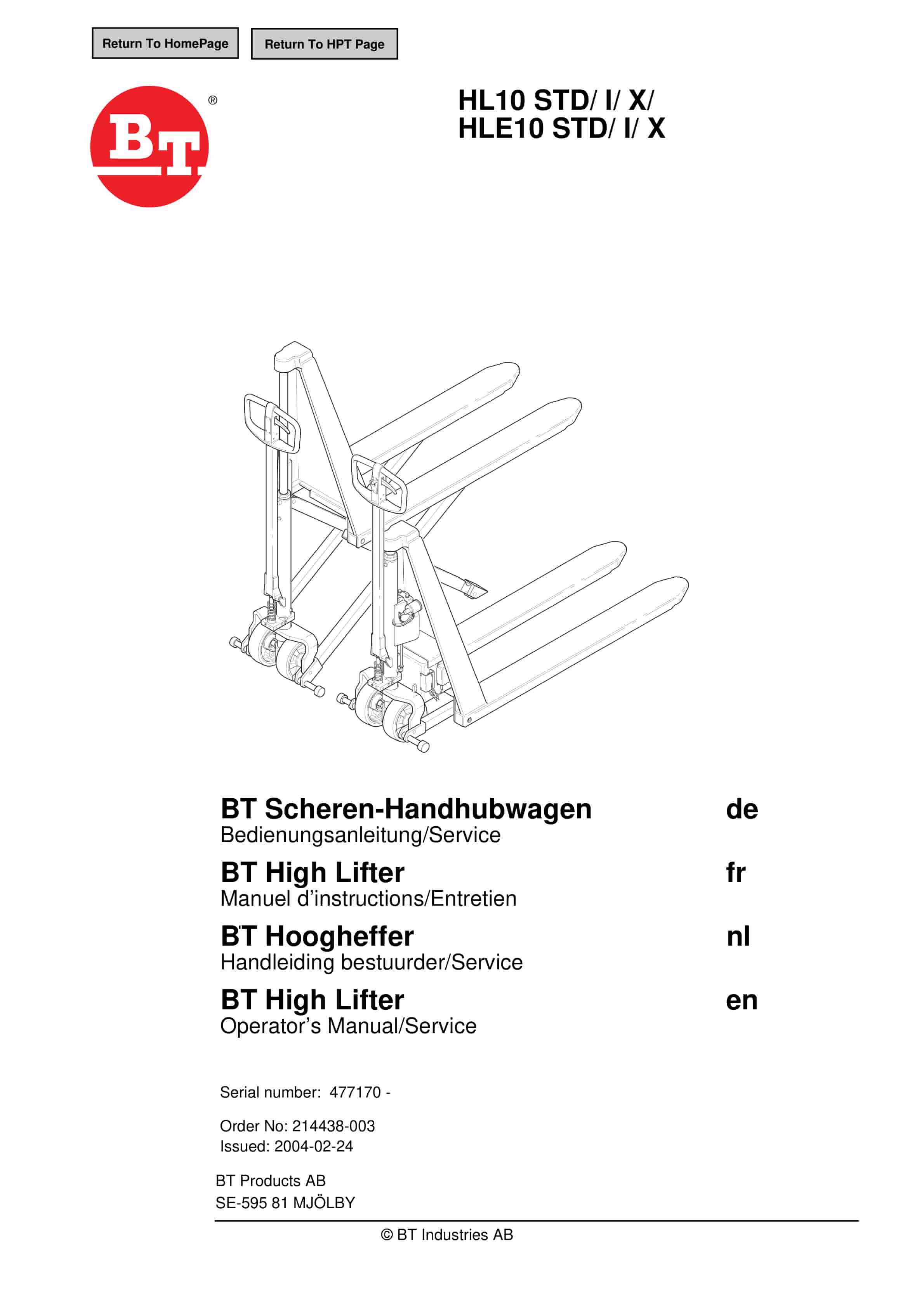
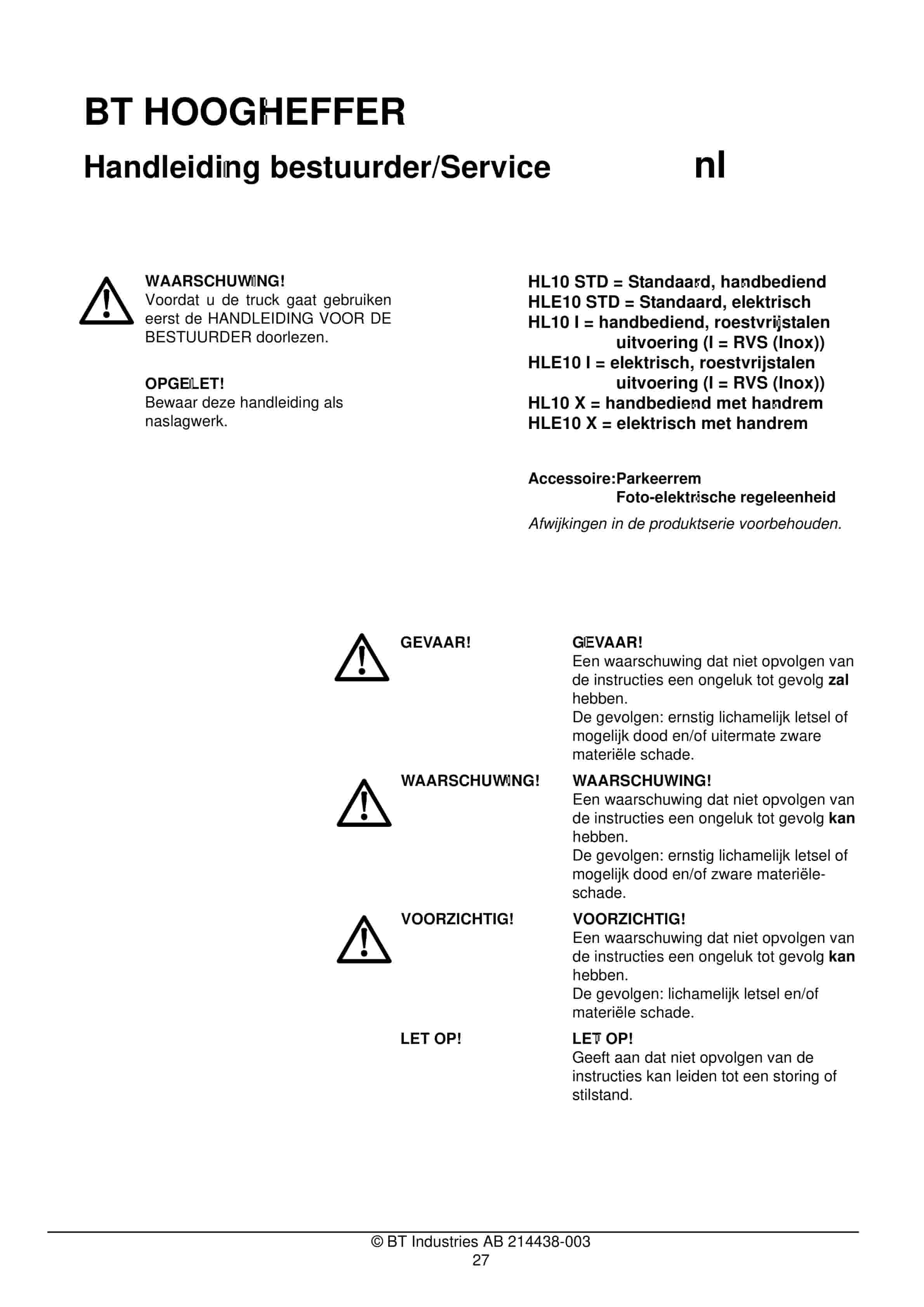
BT HL10 STD, HL10 I, HL10 X, HLE10 STD, HLE10 I, HLE10 X Operator And Service Manual 214438-003
$30.00
BT Service Manual PDF
$30.00
BT Service Manual PDF
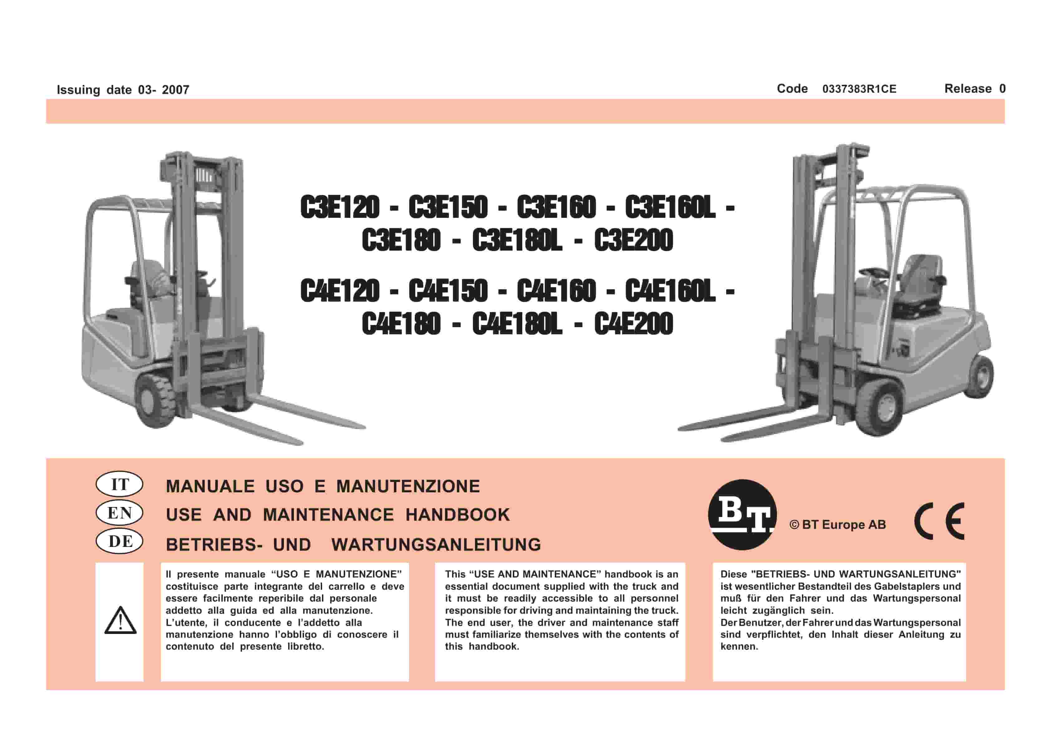
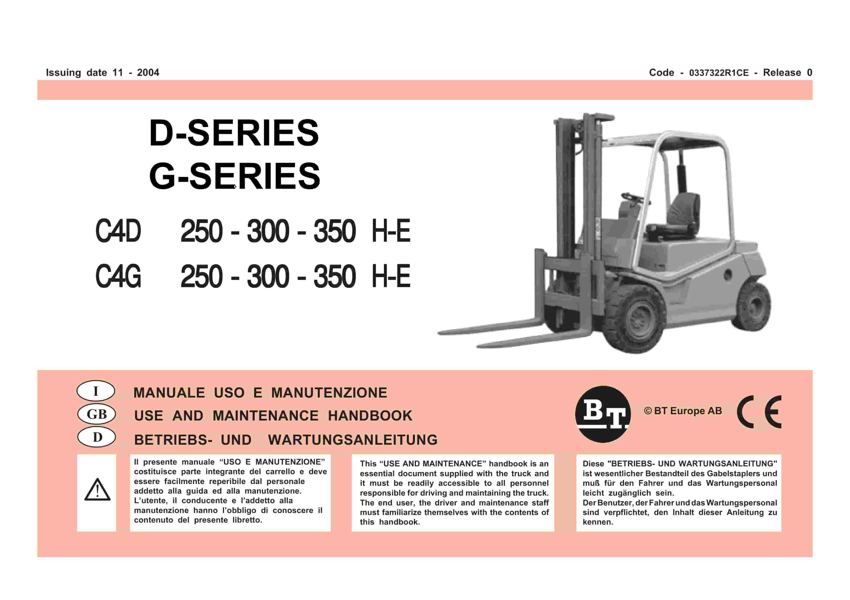
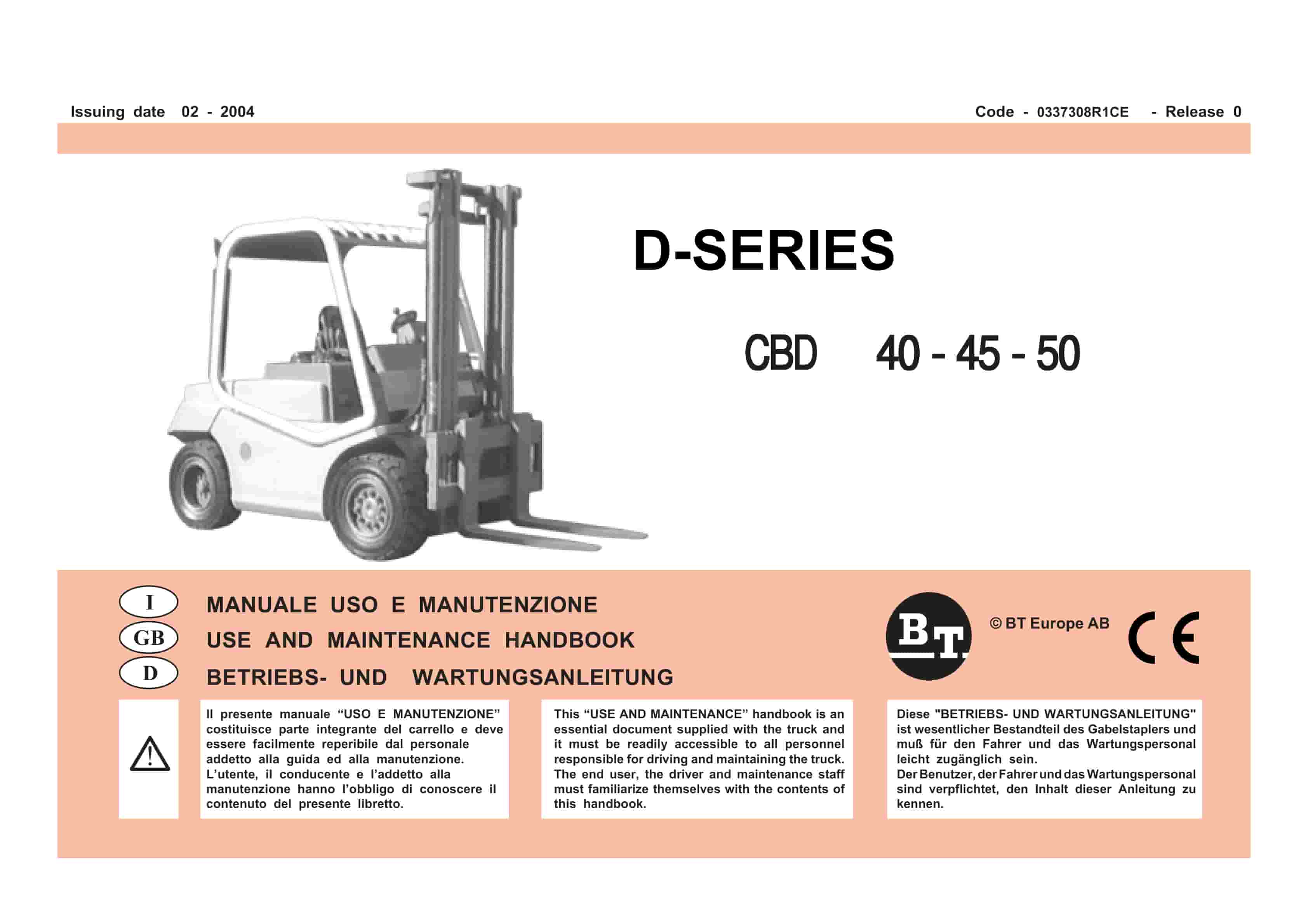
BT D-Series CBD40, CBD45, CBD50 Use And Maintenance Handbook 0337308R1CE
$30.00