

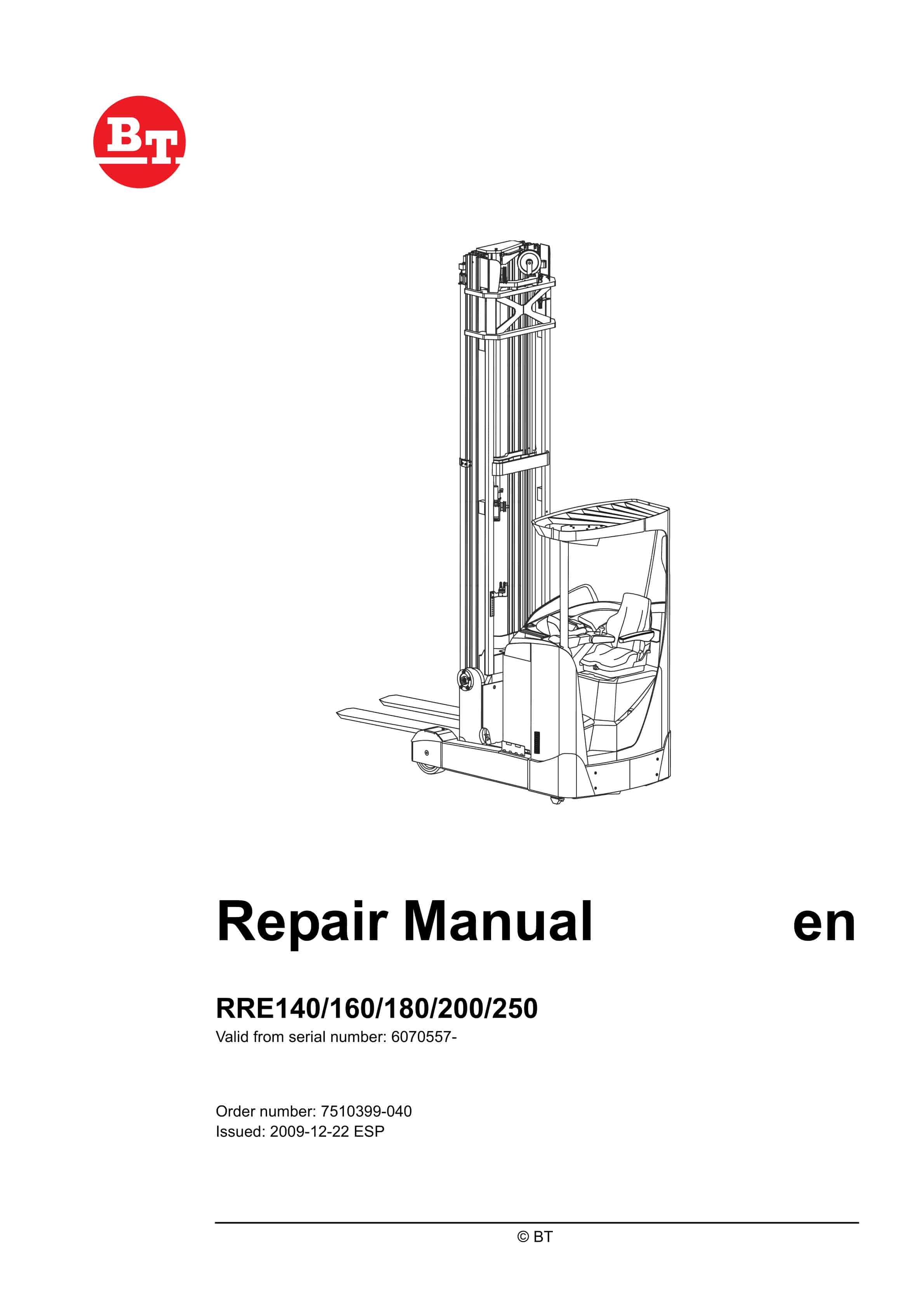
BT RPE140, RPE160, RPE180, RPE200, RPE250 Repair Manual 7510399-040
$30.00
- Type Of Manual: Repair Manual
- Manual ID: 7510399-040
- : Service Manual PDF
- Number of Pages: 728
- Size: 55.2MB
- Format: PDF
Product details
-
Model List:
- RPE140, RPE160, RPE180, RPE200, RPE250
- 1. Contents
- 2. General introduction
- 2.1. How to use the manual
- 2.2. Warning symbols
- 2.3. Pictogram
- 3. General safety rules
- 3.1. Safety while working
- 3.2. Electrical system
- 3.3. Safe lifting
- 4. Function descriptions
- 4.1. Chassis 0000
- 4.1.1. Operators cabin (0500)
- 4.1.2. Cab windows (0530)
- 4.1.3. Drivers seat (0620)
- 4.1.4. Cab heating/ventilation (0630)
- 4.1.5. Driver protection (0840)
- 4.2. Motors 1000
- 4.2.1. General
- 4.2.2. Electric pump motor (1710)
- 4.2.3. Electric steering motor (1730)
- 4.2.4. Fan motor/fan (1740)
- 4.2.5. Electric drive motor (1760)
- 4.3. Drive gear – 2000
- 4.3.1. General
- 4.3.2. Design
- 4.4. Brake system 3100
- 4.4.1. General
- 4.4.2. Drive motor brake (travel brake)
- 4.4.3. Multiple disc brake, support arm (travel brake)
- 4.4.4. Disc brake on the drive motor (parking brake)
- 4.5. Steering system 4000
- 4.5.1. General
- 4.5.2. Design
- 4.5.3. Sensors
- 4.6. Operator compartment
- 4.6.1. Truck control, overview
- 4.6.2. Single control
- 4.6.3. Multi-control
- 4.6.4. Central Information Display – CID
- 4.6.5. Load Information Display – LID (option)
- 4.7. Transducers and sensors (5800)
- 4.7.1. Inductive sensors
- 4.7.2. Position sensor
- 4.7.3. Magnetic sensor
- 4.8. Operation and connection sequences
- 4.9. Functions
- 4.9.1. General overview
- 4.9.2. MCU – main control unit
- 4.9.3. ACT/ACH transistor regulators
- 4.9.4. Start-up
- 4.9.5. Shutdown
- 4.9.6. Driving
- 4.9.7. OTP
- 4.9.8. Steering
- 4.9.9. Hydraulic system
- 4.10. Height preselector, description of function
- 4.10.1. Using the height preselector
- 4.10.2. Symbols
- 4.10.3. Buzzer
- 4.10.4. Height preselector levels
- 4.10.5. Level selection
- 4.10.6. Height programming
- 4.10.7. Height preselector and TruckCom
- 4.10.8. Lift/lowering movement
- 4.10.9. Parameter settings, braking at height preselection
- 4.11. Hydraulic system 6000
- 4.11.1. General
- 4.11.2. Tank
- 4.11.3. Filter
- 4.11.4. Hydraulic pump
- 4.11.5. Valve block
- 4.11.6. Cylinders
- 4.11.7. Lift and lowering function
- 4.11.8. Extra functions
- 4.11.9. Cabin tilt (RRE Ergo)
- 4.12. Mast 7000
- 4.12.1. Mast and reach carriage
- 4.13. Lifting devices
- 4.13.1. Fork extensions
- 4.13.2. Telescopic forks
- 4.14. Accessories – 9000
- 4.14.1. Radio equipment
- 4.14.2. Extra work lights
- 4.14.3. Extra warning light/alarm
- 4.14.4. Direction indicators
- 4.14.5. Travel alarm
- 4.14.6. Positioning/TV equipment
- 4.14.7. Extra electrical equipment
- 4.14.8. Extra equipment, miscellaneous
- 5. Parameters
- 5.1. General
- 5.2. Displaying/changing parameters
- 5.3. Operator parameters
- 5.3.1. Overview
- 5.3.2. Coupling to logged-in operator
- 5.3.3. Description
- 5.4. General service parameters
- 5.4.1. Overview
- 5.4.2. Description
- 5.4.3. Service parameters, travel functions
- 5.4.4. Overview
- 5.4.5. Description
- 5.5. Service parameters, hydraulics
- 5.5.1. Overview
- 5.5.2. Description
- 5.6. Service parameters, CID
- 5.6.1. Overview
- 5.6.2. Description
- 5.7. General factory parameters
- 5.7.1. Overview
- 5.7.2. Description
- 5.8. Factory parameters, activation of options
- 5.9. Factory parameters, calibration
- 6. Installation
- 6.1. Transporting the truck
- 6.1.1. Method 1
- 6.1.2. Method 2
- 6.2. Initial operation
- 6.2.1. Tool
- 6.2.2. Battery
- 6.2.3. Mast, fitting
- 6.2.4. Parameters on initial operation
- 6.2.5. Parameters for optional equipment
- 6.2.6. Test driving
- 7. Maintenance
- 7.1. Introduction, maintenance
- 7.2. Safety regulations during maintenance work
- 7.3. Periodic maintenance
- 7.3.1. Every 500 B-hours/180 days
- 7.3.2. Every 1,000 B-hours/360 days
- 7.3.3. Every 2,000 B-hours/720 days
- 7.3.4. Every 3,000 B-hours/1,080 days
- 7.3.5. Every 5,000 B-hours/1,800 days
- 7.3.6. Annual status inspection
- 7.4. Maintenance instructions
- 7.4.1. Cleaning and washing
- 8. Troubleshooting
- 8.1. Abbreviations used in this section
- 8.2. Truck help functions
- 8.2.1. Error log menu
- 8.2.2. Error information menu
- 8.2.3. Diagnostic screens
- 8.3. Initial troubleshooting
- 8.4. Troubleshooting using catch symbol
- 8.5. Troubleshooting using error code
- 8.5.1. CID, warnings and errors
- 8.5.2. MCU and other warnings and errors
- 8.5.3. Drive system error
- 8.5.4. Hydraulic system error
- 8.5.5. Steering system, warnings and errors
- 8.5.6. GFU, warnings and errors
- 8.6. Troubleshooting without indications
- 8.6.1. Mechanical brake (3000)
- 8.6.2. Steering (4000)
- 8.6.3. Telescopic forks
- 8.6.4. Log-in normal but one or more functions cannot be used.
- 9. Frame/Chassis 0000
- 9.1. General
- 9.2. Motor hood (0340)
- 9.2.1. Opening the motor compartment
- 9.3. Battery compartment components (0390)
- 9.3.1. Adjusting the battery bed
- 9.4. Operators cab (0500)
- 9.4.1. Cab tilting RRE 140 – 250 Ergo
- 9.4.2. Cab windows (0530)
- 9.4.3. Cab door (0550)
- 9.5. Operator compartment (0600)
- 9.5.1. Operators seat (0620)
- 9.5.2. Cab heating/ventilation (0630)
- 9.5.3. Internal fittings (0680)
- 9.5.4. Disassembling/assembling the floor plate, B version 0680
- 9.6. Safety equipment (0800)
- 9.6.1. Checking the overhead guard (0810)
- 9.6.2. Adjusting the tilt stops (0840)
- 10. Motors 1000
- 10.1. Motor sensors
- 10.1.1. Temperature sensor
- 10.1.2. Replacing the motor speed sensor
- 10.2. Pump motor (1710)
- 10.2.1. General
- 10.2.2. Replacing the bearing on the pump motor
- 10.3. Steering motor and steering unit (1730)
- 10.3.1. General
- 10.3.2. Layout of the flange holes
- 10.3.3. Removing the steering motor from the truck
- 10.3.4. Fitting the steering motor in the truck
- 10.4. Fan motor/fan (1740)
- 10.4.1. General
- 10.4.2. Replacing the frequency converter cooling fan
- 10.4.3. Replacing the motor compartment cooling fan
- 10.5. Drive motor (1760)
- 10.5.1. General
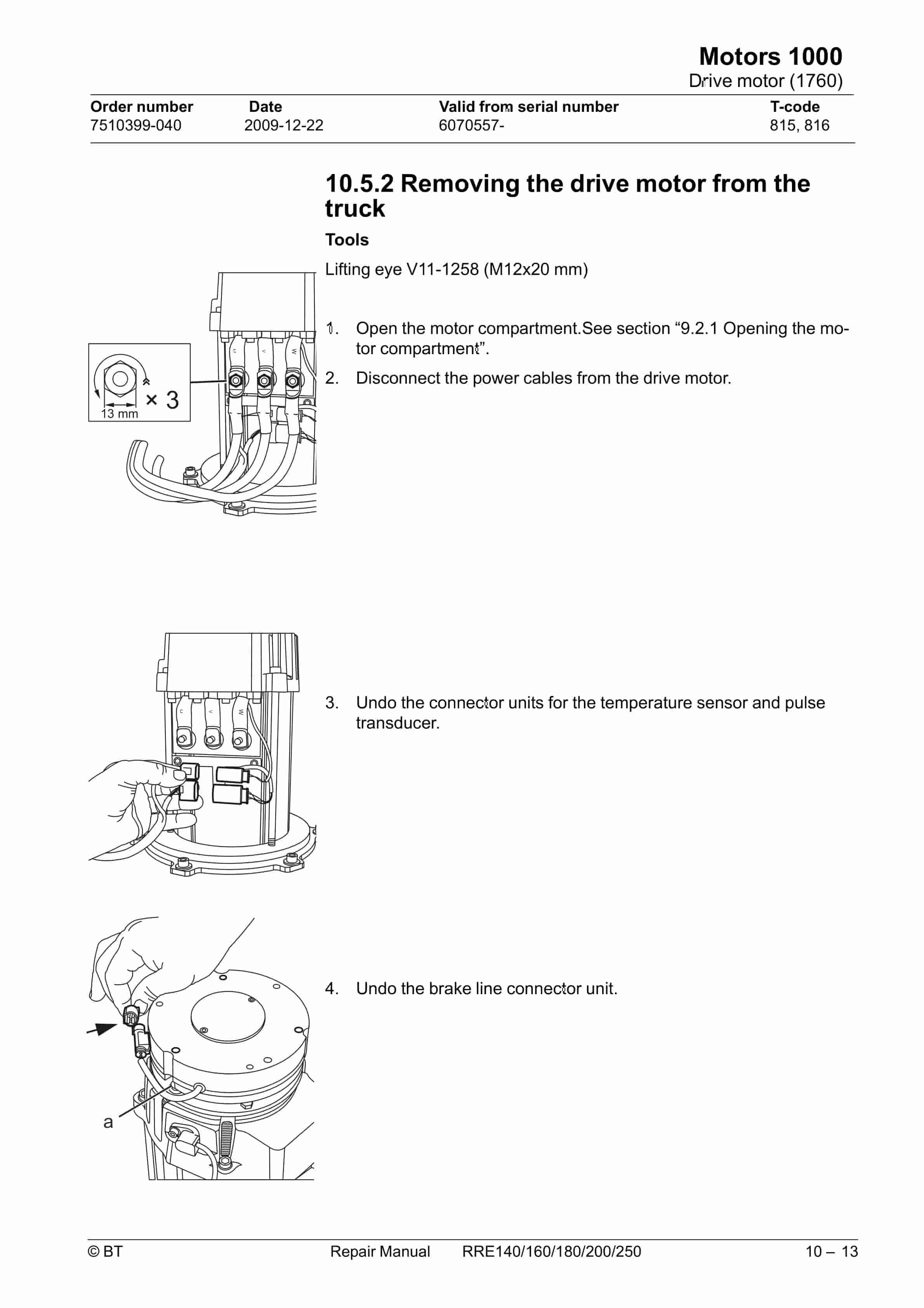
- 10.5.2. Removing the drive motor from the truck
- 10.5.3. Dismantling the drive motor
- 10.5.4. Cleaning
- 10.5.5. Assembling the drive motor
- 10.5.6. Fitting the drive motor in the truck
- 11. Drive gear 2000
- 11.1. General
- 11.2. Repairs/servicing
- 11.3. Actions
- 11.3.1. Checking the oil level
- 11.3.2. Changing the oil
- 11.3.3. Leakage from the bottom cover
- 11.3.4. Replacing the drive gear
- 12. Brake and wheel 3000
- 12.1. Travel brake system (3100)
- 12.1.1. Removing the support arms multiple disc brake
- 12.1.2. Dismantling the multiple disc brake
- 12.1.3. Installing the multiple disc brake in the truck
- 12.1.4. Checking the wheel brakes brake force
- 12.2. Parking brake (3300)
- 12.2.1. General
- 12.2.2. Emergency release of the parking brake
- 12.2.3. Checking the brake force
- 12.2.4. Removing the parking brake from the truck
- 12.2.5. Installing the parking brake in the truck
- 12.3. Drive wheel (3530)
- 12.3.1. General
- 12.3.2. Removing the drive wheel from the truck
- 12.3.3. Installing the drive wheel on the truck
- 12.4. Wheel bolt (3530)
- 12.4.1. General
- 12.4.2. Replacing wheel bolts
- 12.5. Support arm wheel (3550)
- 12.5.1. Removing the support arm wheel from the truck
- 12.5.2. Replacing a wheel bearing – braked wheel (A)
- 12.5.3. Replacing a wheel bearing – unbraked wheel (B)
- 12.5.4. Fitting the support arm wheel to the truck
- 12.5.5. Wheel wear and tear
- 13. Steering system 4000
- 13.1. Electric steering wheel (4310)
- 13.1.1. General
- 13.1.2. Replacing the pulse transducer on the steering wheel module
- 13.1.3. Removing the operating console from the truck
- 13.1.4. Replacing the wiring harness in the operating console
- 13.1.5. Fitting the operating console in the truck
- 13.2. Steering reference sensor (4350)
- 13.2.1. General
- 13.2.2. Replacing the reference transducer B17
- 13.3. Steering bearings (4380)
- 13.3.1. Removing a steering bearing from the drive gear
- 13.3.2. Fitting a steering bearing on the drive gear
- 14. Electrical system 5000
- 14.1. Battery (5110)
- 14.1.1. Battery recommendation
- 14.1.2. Battery installation
- 14.2. LID (5200)
- 14.2.1. Replacement of LID
- 14.2.2. Replacement of LID cold store cab
- 14.3. Replacing pedals
- 14.3.1. Replacing/repairing safety pedal
- 14.4. Control console (5510)
- 14.4.1. General
- 14.4.2. Replacement/installation of a control
- 14.4.3. Replacing the multi-function control
- 14.4.4. Remove the control console from the truck
- 14.4.5. Replacing the access cards circuit board
- 14.4.6. Dismantling the control console
- 14.4.7. Assembling the control console
- 14.4.8. Placing the control console in the truck
- 14.5. Magnetic sensor (5850)
- 14.5.1. General
- 14.5.2. Replacing the magnetic sensor B47
- 14.5.3. Reference magnet
- 14.6. Parameter settings
- 14.6.1. Configuration menu
- 14.7. PIN menu
- 14.7.1. Menu for activating a PIN block
- 14.7.2. Menu for programming a PIN (P)
- 14.8. Calibrations
- 14.8.1. Calibrating the hydraulic function control
- 14.8.2. Height measurement/reach movement length calibration
- 14.8.3. Valve calibration
- 14.8.4. Weight calibration
- 14.9. Changing cabling
- 14.10. Main computer unit MCU (A5)
- 14.10.1. Installing a new card in the truck.
- 14.10.2. Voltage feed
- 14.10.3. Battery minus
- 14.10.4. Internal status monitoring
- 14.10.5. Resetting the battery indicator
- 15. Hydraulic system 6000
- 15.1. Hydraulic hygiene
- 15.1.1. Cleaning
- 15.1.2. Packaging
- 15.1.3. Handling
- 15.1.4. Storage
- 15.1.5. Procedure
- 15.2. Hydraulic unit (6100)
- 15.2.1. Emptying the hydraulic tank
- 15.2.2. Hydraulic system, bleeding
- 15.2.3. Remove the pump motor from the truck
- 15.2.4. Replacing the hydraulic pump
- 15.2.5. Fitting the pump motor in the truck
- 15.3. Main valve (6210)
- 15.3.1. Emergency lowering of forks
- 15.3.2. Replacing the main valve block
- 15.3.3. Replacing the Q4 valve
- 15.3.4. Adjusting the maximum opening pressure
- 15.4. Hydraulic couplings (6230)
- 15.4.1. Hydraulic couplings, tightening torques
- 15.4.2. Quick coupling
- 15.5. Hydraulic system, mast (6300)
- 15.5.1. Mast-mounted hose reel (6370)
- 15.5.2. Fitting the hose reel
- 15.5.3. Checks after fitting
- 15.6. Main lift cylinder 6610
- 15.6.1. General
- 15.6.2. Overview
- 15.6.3. Remove the lift cylinder from the mast
- 15.6.4. Replacing the hose rupture valve
- 15.6.5. Dismantling the cylinder
- 15.6.6. Dismantling the piston.
- 15.6.7. Dismantling the cylinder head
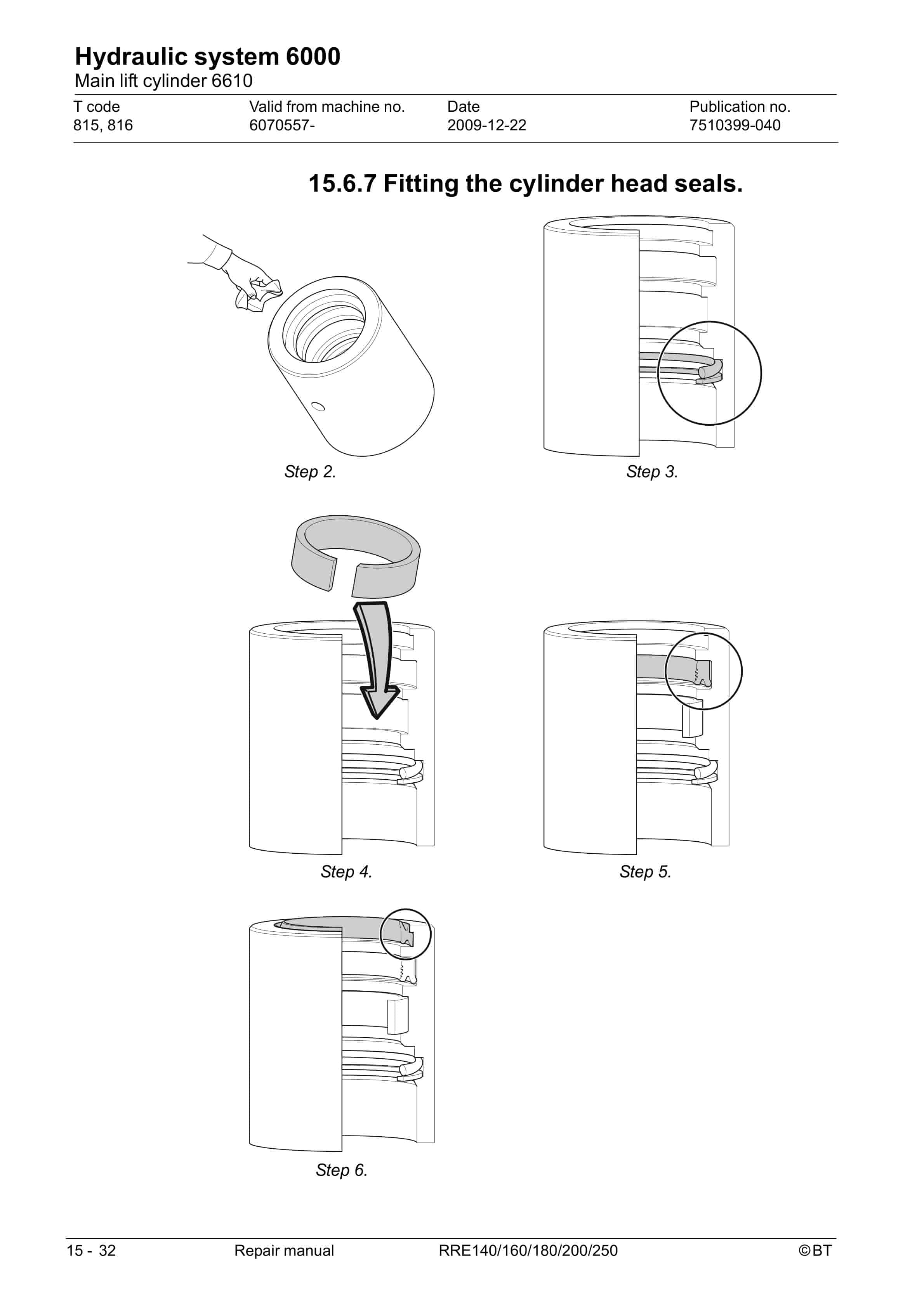
- 15.6.8. Fitting the cylinder head seals.
- 15.6.9. Fitting the piston seals.
- 15.6.10. Assembling the cylinder
- 15.6.11. Assembling the cylinder in the mast
- 15.7. Free lift cylinder (6620)
- 15.7.1. General
- 15.7.2. Removing the free lift cylinder from the truck
- 15.7.3. Replacing the hose rupture valve, free lift cylinder
- 15.7.4. Fitting the free lift cylinder in the truck
- 15.8. Reach cylinder (6650)
- 15.8.1. General
- 15.8.2. Remove the reach cylinder from the truck
- 15.8.3. Fitting the reach cylinder in the truck
- 15.9. Fork tilt cylinder (6660)
- 15.9.1. General
- 15.9.2. Remove the tilt cylinder from the truck
- 15.9.3. Fit the tilt cylinder in the truck
- 15.10. Cab tilt cylinder (6660)
- 15.10.1. General
- 15.10.2. Overview
- 15.10.3. Dismantling the cylinder
- 15.10.4. Dismantling the piston rod
- 15.10.5. Dismantling the cylinder head
- 15.10.6. Fitting the cylinder head seals.
- 15.10.7. Dismantling the piston rod
- 15.10.8. Assembling the cylinder
- 15.11. Sideshift cylinder (6670)
- 15.11.1. General
- 15.11.2. Overview
- 15.11.3. Dismantling the cylinder from the truck
- 15.11.4. Dismantling the cylinder
- 15.11.5. Dismantling the piston rod
- 15.11.6. Dismantling the cylinder head
- 15.11.7. Fitting the cylinder head seals.
- 15.11.8. Dismantling the piston rod
- 15.11.9. Assembling the cylinder
- 15.11.10. Refitting the cylinder in the truck
- 16. Mast/Lift system 7000
- 16.1. Main mast 1.6-2.5 t (7100)
- 16.1.1. Replacing the complete mast
- 16.1.2. Removing the mast from the truck
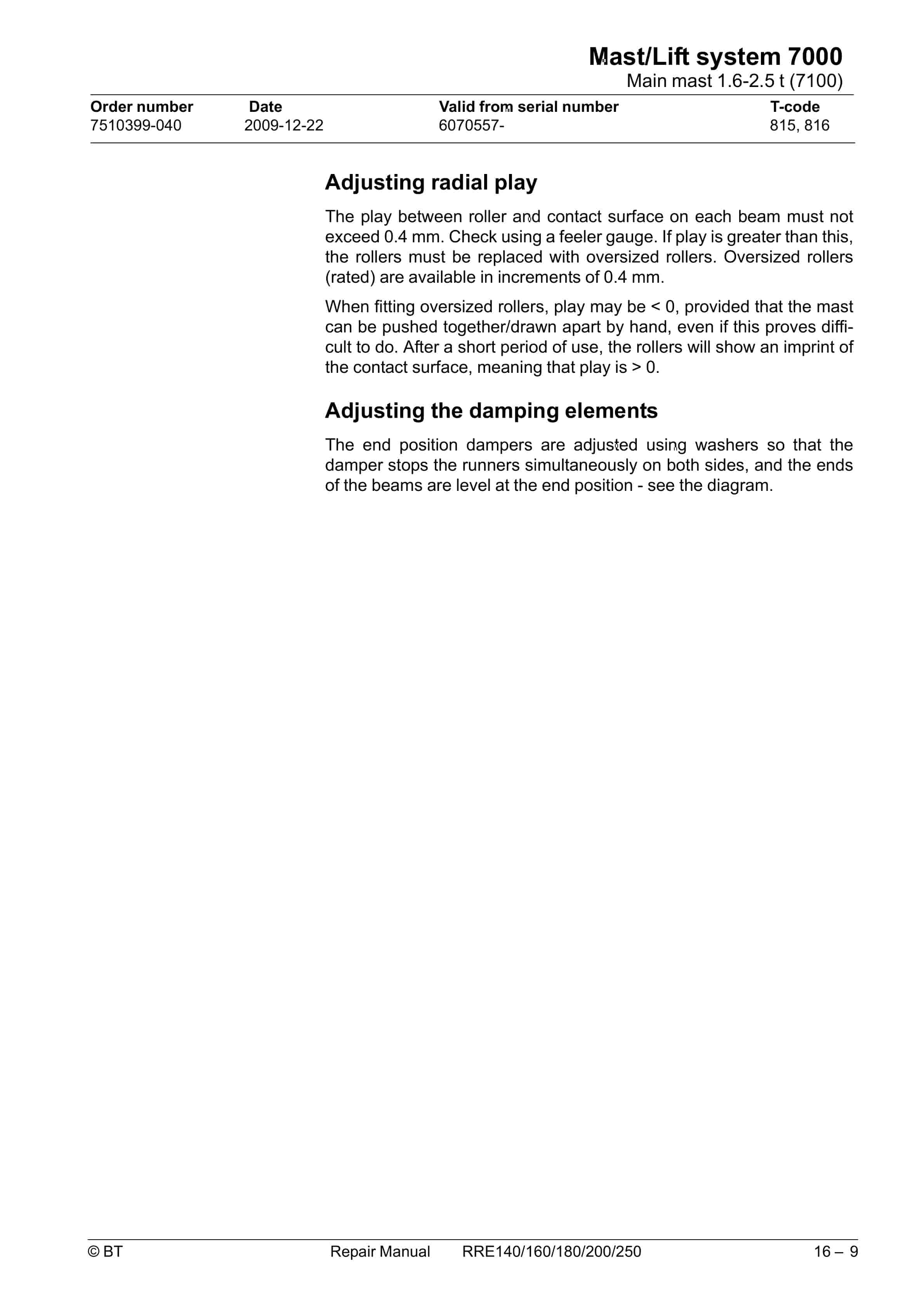
- 16.1.3. Adjusting mast play
- 16.1.4. Replacing the masts damper plates
- 16.1.5. Fitting the mast on the truck
- 16.2. Main lift chain system (7120)
- 16.2.1. General
- 16.2.2. Inspecting the chain
- 16.2.3. Lubricating the chain
- 16.2.4. Main lift chain system, adjusting the fork-to-floor distance
- 16.3. Reach carriage (7190)
- 16.3.1. Adjusting radial play in the reach carriage
- 16.3.2. Adjusting axial play in the reach carriage
- 16.4. Lifting devices (7400)
- 16.4.1. Forks
- 16.4.2. Forks, repairs and testing
- 16.5. Fork carriage
- 16.5.1. Checking the fork carriages wear strip
- 16.5.2. Lubricating the fork carriage
Related products
-
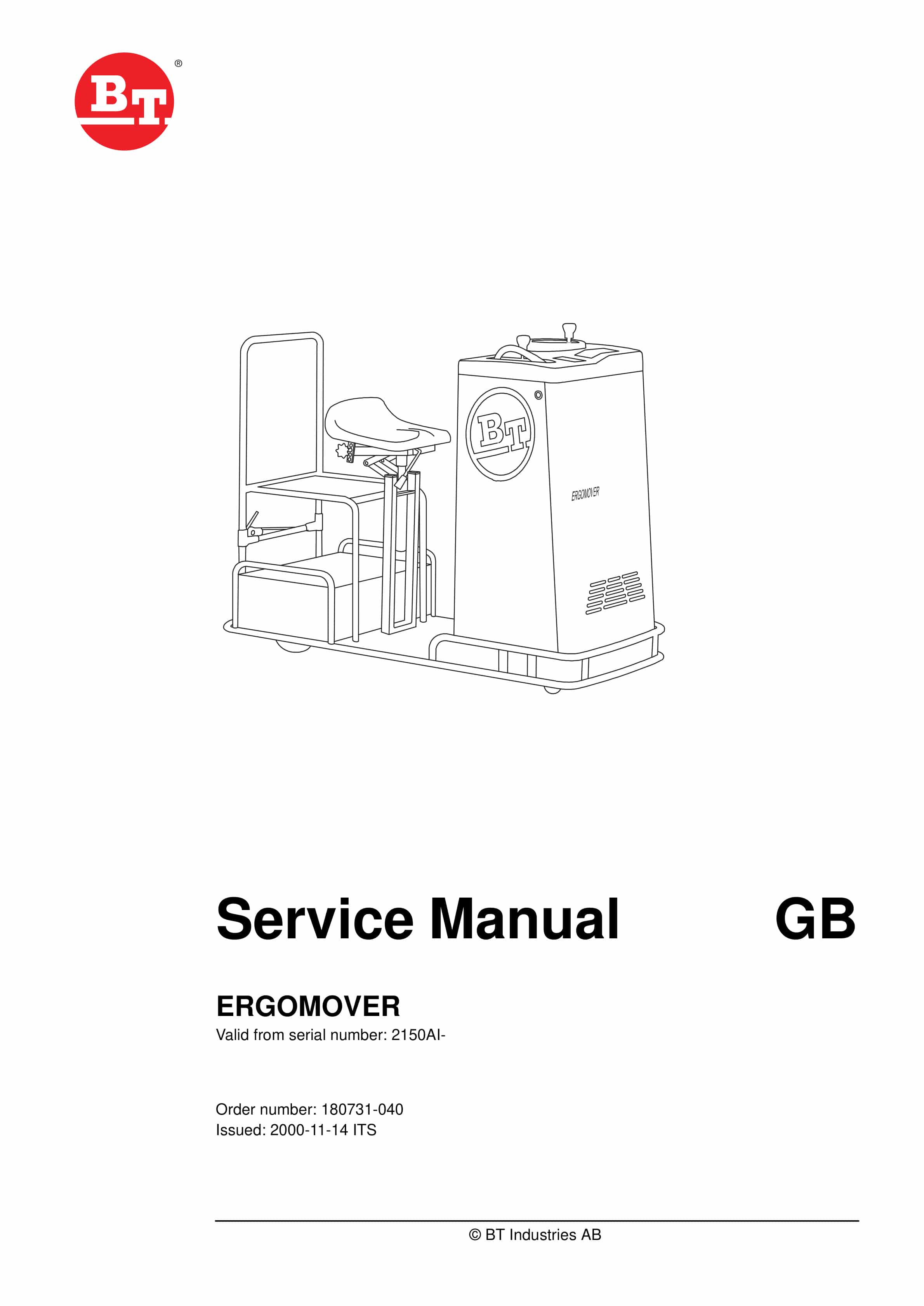
BT ERGOMOVER Service Manual 180731-040
$30.00 Add to cart -
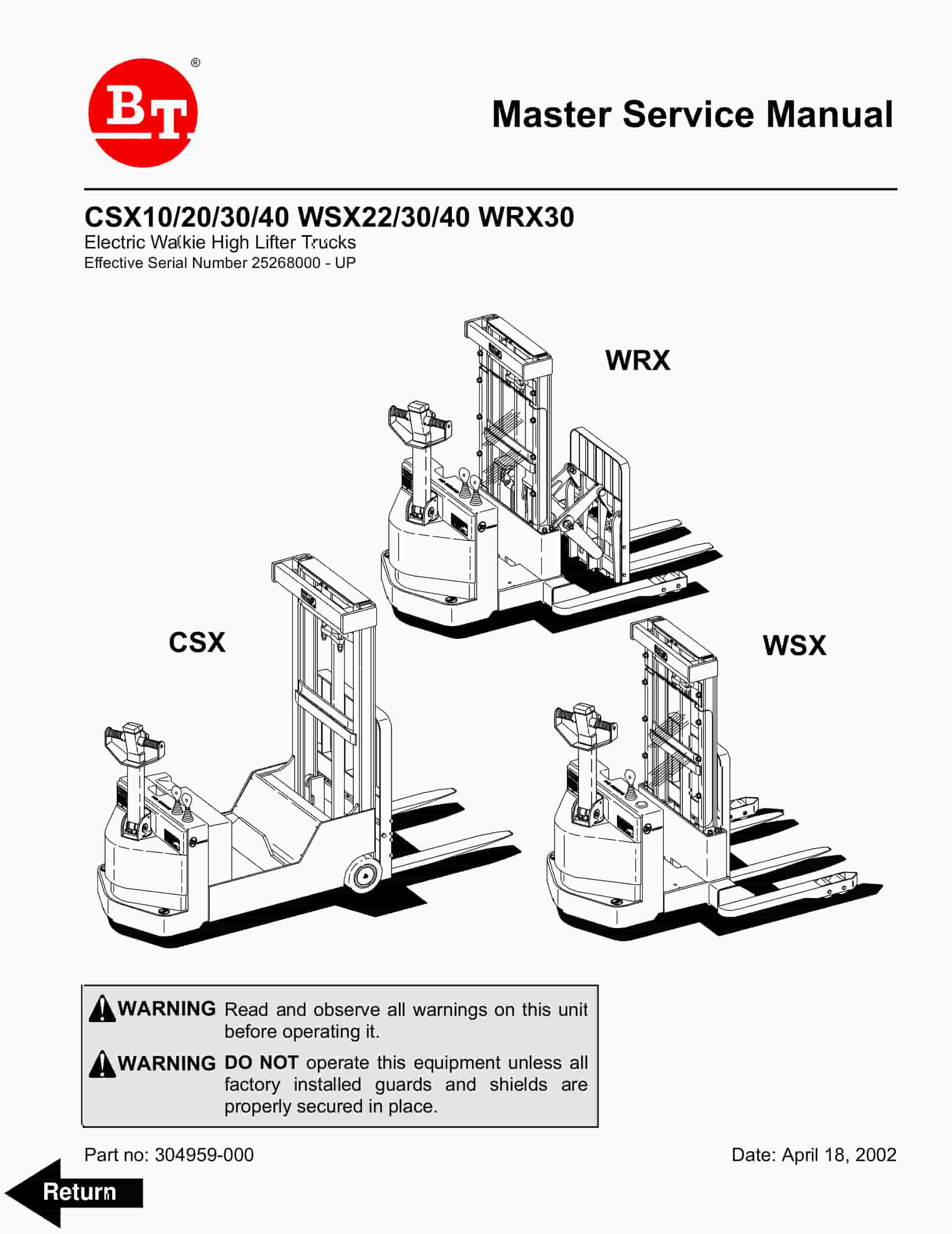
BT CSX10, CSX20, CSX30, CSX40, WSX22, WSX30, WSX40, WRX30 Electric Walkie High Lifter Truck Service Manual 304959-000
$30.00 Add to cart -
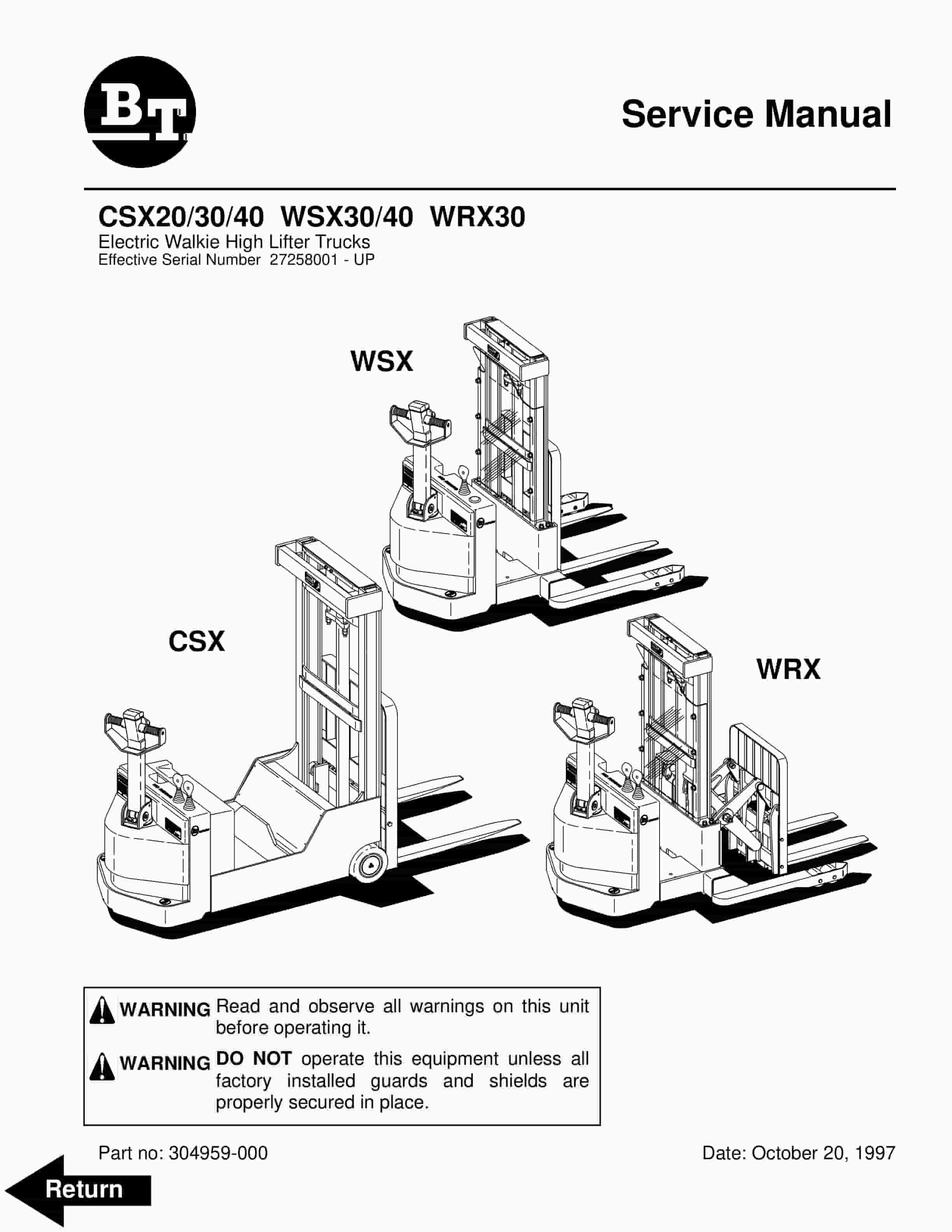
BT CSX20, CSX30, CSX40, WSX30, WSX40, WRX30 Electric Walkie High Lifter Truck Service Manual 304959-000
$30.00 Add to cart -
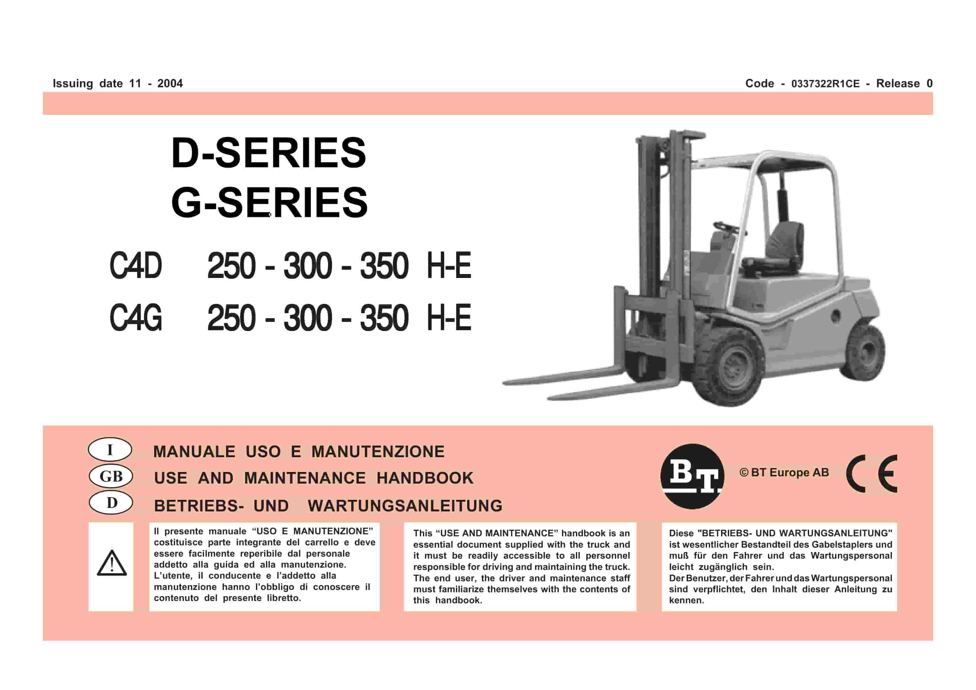
BT D-G-Series C4D250H-E, C4D300H-E, C4D350H-E, C4G250H-E, C4G300H-E, C4G350H-E Use And Maintenance Handbook 0337322R1CE
$30.00 Add to cart -
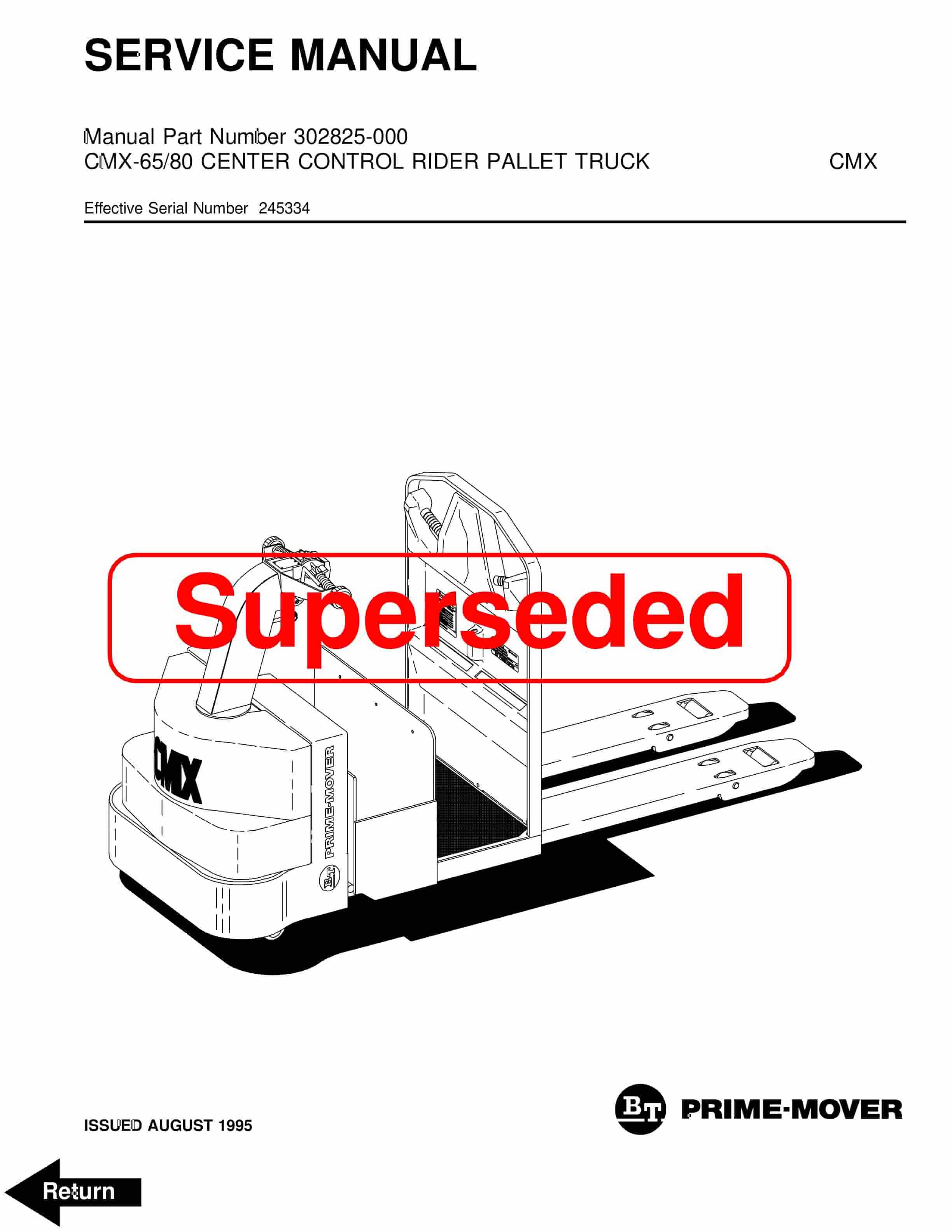
BT CMX-65, CMX-80 Center Control Riding Pallet Truck Service Manual 302825-000
$30.00 Add to cart


