

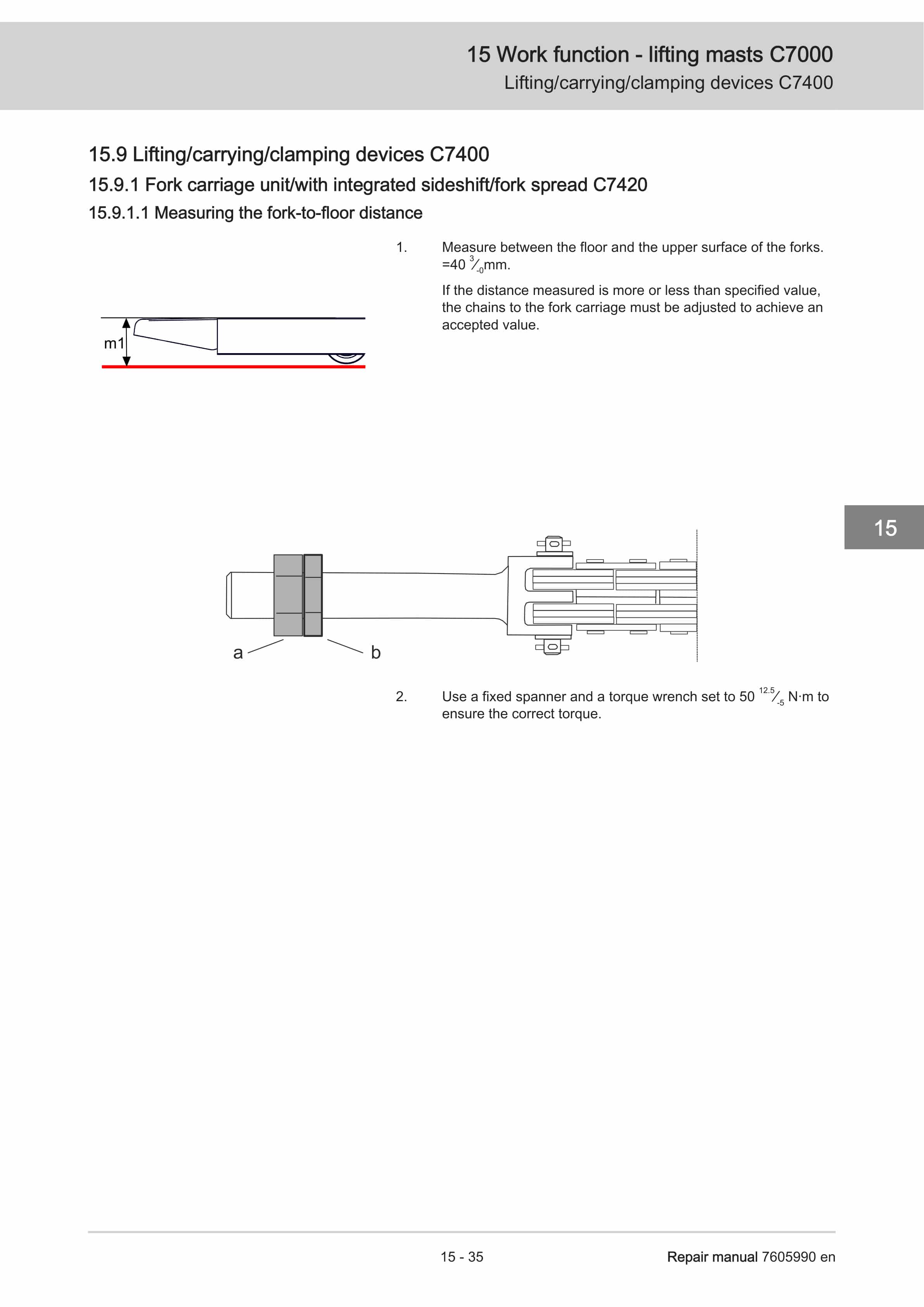
BT SPE120XR, SPE120XRD Repair Manual 7605990-040
$30.00
- Type Of Manual: Repair Manual
- Manual ID: 7605990-040
- : Service Manual PDF
- Number of Pages: 580
- Size: 78.8MB
- Format: PDF
Product details
-
Model List:
- SPE120XR, SPE120XRD
- 1. General introduction
- 1.1. Warning levels and symbols
- 1.2. Pictograms
- 1.3. Abbreviations
- 2. General safety rules
- 2.1. Authorised personnel
- 2.2. Work safety
- 2.3. Electrical system
- 2.3.1. Electrostatic risks
- 2.3.2. Battery handling
- 2.4. Safe lifting
- 2.5. Product modification
- 2.6. Software
- 2.7. Hydraulic system
- 3. Operating principle
- 3.1. Description
- 3.1.1. Battery is connected
- 3.1.2. Login via keypad
- 3.1.3. Login via ID key option
- 3.1.4. Tiller arm lowered for driving
- 3.1.5. Driving in fork direction
- 3.1.6. Driving in the drive wheel direction
- 3.1.7. Braking in neutral
- 3.1.8. Reverse braking
- 3.1.9. Mechanical braking
- 3.1.10. Emergency reversal
- 3.2. Description
- 4. Parameters
- 4.1. Display/change parameters
- 4.2. Parameters in general
- 4.3. Parameter list
- 5. Installation
- 5.1. Transport
- 5.1.1. Transporting the mast
- 5.2. Lifting the truck
- 5.2.1. Lifting the truck
- 5.2.2. Lift using a jack
- 5.3. Commissioning
- 5.3.1. Parameters on commissioning
- 5.3.2. Battery
- 6. Maintenance
- 6.1. Introduction
- 6.2. Maintenance instructions
- 6.2.1. Cleaning
- 6.2.2. High-pressure washers
- 6.2.3. Degreasing agents
- 6.2.4. Cleaning the exterior
- 6.2.5. Cleaning the chain
- 6.2.6. Cleaning the motor compartment
- 6.2.7. Electric components
- 6.2.8. Hydraulic system
- 6.2.9. Signs, warnings and adhesive labels
- 6.3. Lubricants specification
- 6.4. Periodic maintenance
- 7. Troubleshooting
- 7.1. Initial troubleshooting
- 7.2. Concluding troubleshooting
- 7.3. Auxiliary functions
- 7.3.1. Towing a defective truck
- 7.3.2. Emergency driving mode
- 7.3.3. Error code history
- 7.3.4. Extended error log
- 7.3.5. Built-in test function for the tiller arm
- 7.3.6. Digital input/output status
- 7.3.7. Service information
- 7.4. Troubleshooting using error codes
- 7.4.1. List of error codes
- 8. Chassis C0000
- 8.1. Overview
- 8.2. Inspection of the rear chassis
- 8.3. Frame, chassis C0300
- 8.3.1. Inspection covers C0340
- 8.3.2. Support arms, stabilizers C0350
- 8.3.3. Battery compartment parts C0390
- 8.4. Frame/chassis components C0400
- 8.4.1. Motor mount/brackets C0450
- 8.5. Operator compartment, cab C0500
- 8.5.1. Platform including fixing points C0560
- 8.6. Safety equipment C0800
- 8.6.1. Operator protection C0840
- 8.6.2. Signs, warnings, labels C0850
- 9. Motors C1000
- 9.1. Electric motors C1700
- 9.1.1. Electric pump motor C1710
- 9.1.2. Electric steering motor C1730
- 9.1.3. Electric fan motor/fan C1740
- 9.1.4. Electric drive motor C1760
- 10. Transmission/Drive gear C2000
- 10.1. Drive unit, final gear C2500
- 10.1.1. Drive unit/gear C2550
- 11. Brake/wheel/track system C3000
- 11.1. Travel brake system C3100
- 11.1.1. Description
- 11.2. Parking brake details C3300
- 11.2.1. Electrical parking brake, magnet brake C3370
- 11.3. Wheels C3500
- 11.3.1. Drive wheel C3530
- 11.3.2. Support arm wheels/castor wheels C3540
- 11.3.3. Fork wheels/support arm wheels C3550
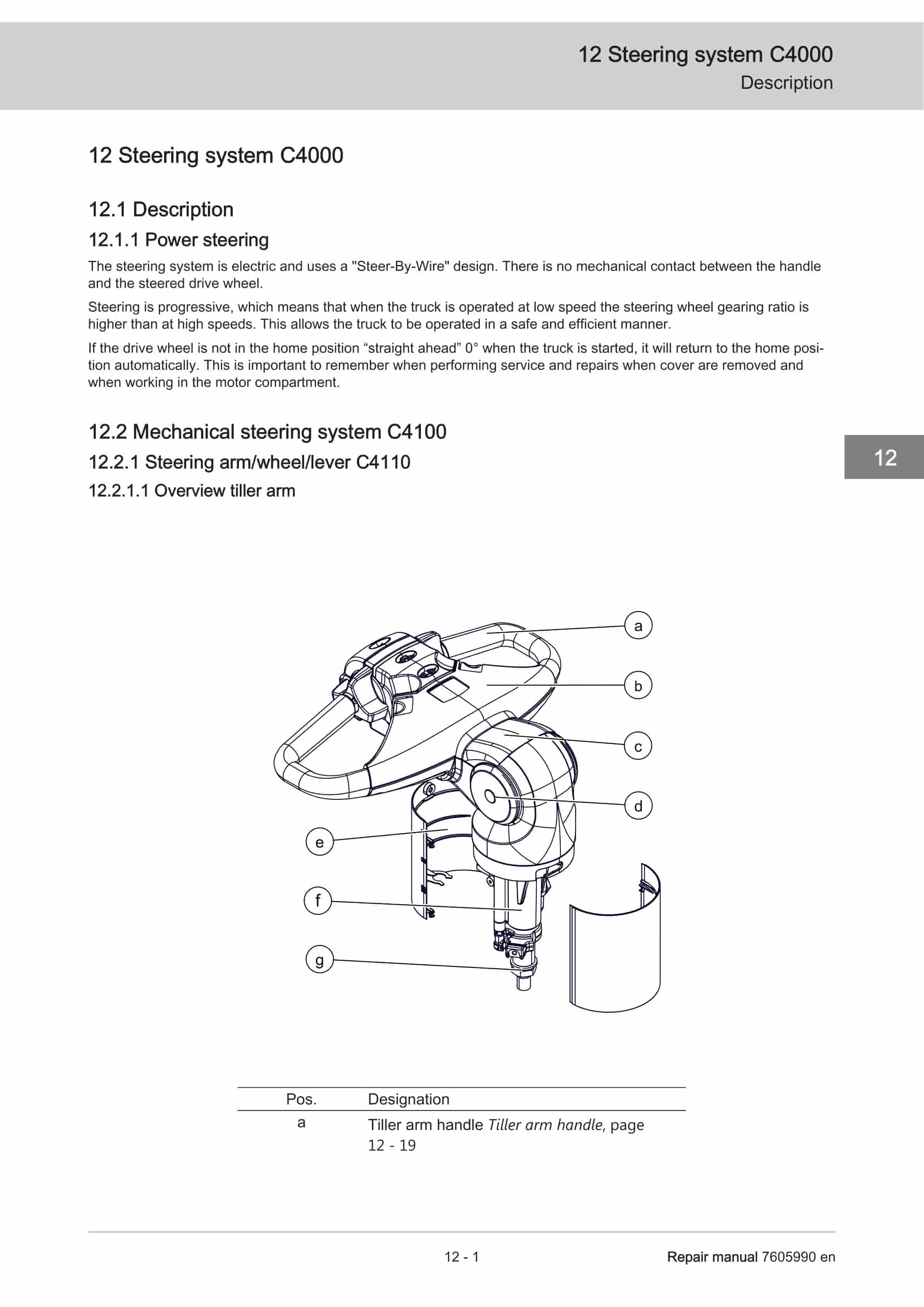
- 12. Steering system C4000
- 12.1. Description
- 12.1.1. Power steering
- 12.2. Mechanical steering system C4100
- 12.2.1. Steering arm/wheel/lever C4110
- 12.3. Electric steering system C4300
- 12.3.1. Overview
- 12.3.2. Steering angle sensor C4350
- 13. Electrical system C5000
- 13.1. Description
- 13.1.1. Using the anti-static carpet
- 13.2. Programming tools
- 13.2.1. TruckCom
- 13.3. General electric equipment C5100
- 13.3.1. Battery C5110
- 13.3.2. General alarm signals (audible/visual) C5160
- 13.3.3. Battery charger (built-in) C5170
- 13.3.4. Battery cut out switch, main contactor C5190
- 13.4. Instrument panel, display C5200
- 13.4.1. Menu
- 13.4.2. Hour counter, tachograph C5290
- 13.5. Control system travel function C5300
- 13.5.1. Direction selector/speed regulator
- 13.5.2. Pressure equalization
- 13.5.3. Weighing system
- 13.5.4. Display
- 13.5.5. Symbols on keypad and display
- 13.5.6. Option buttons
- 13.5.7. Signal buttons
- 13.5.8. Lifting and lowering control
- 13.5.9. Hour meter
- 13.5.10. Battery indicator
- 13.5.11. Safety reversing
- 13.6. Power system travel function C5400
- 13.6.1. Overview
- 13.6.2. Transistor panel C5460
- 13.7. Control system, working function C5500
- 13.7.1. Work function harnesses/fuse C5590
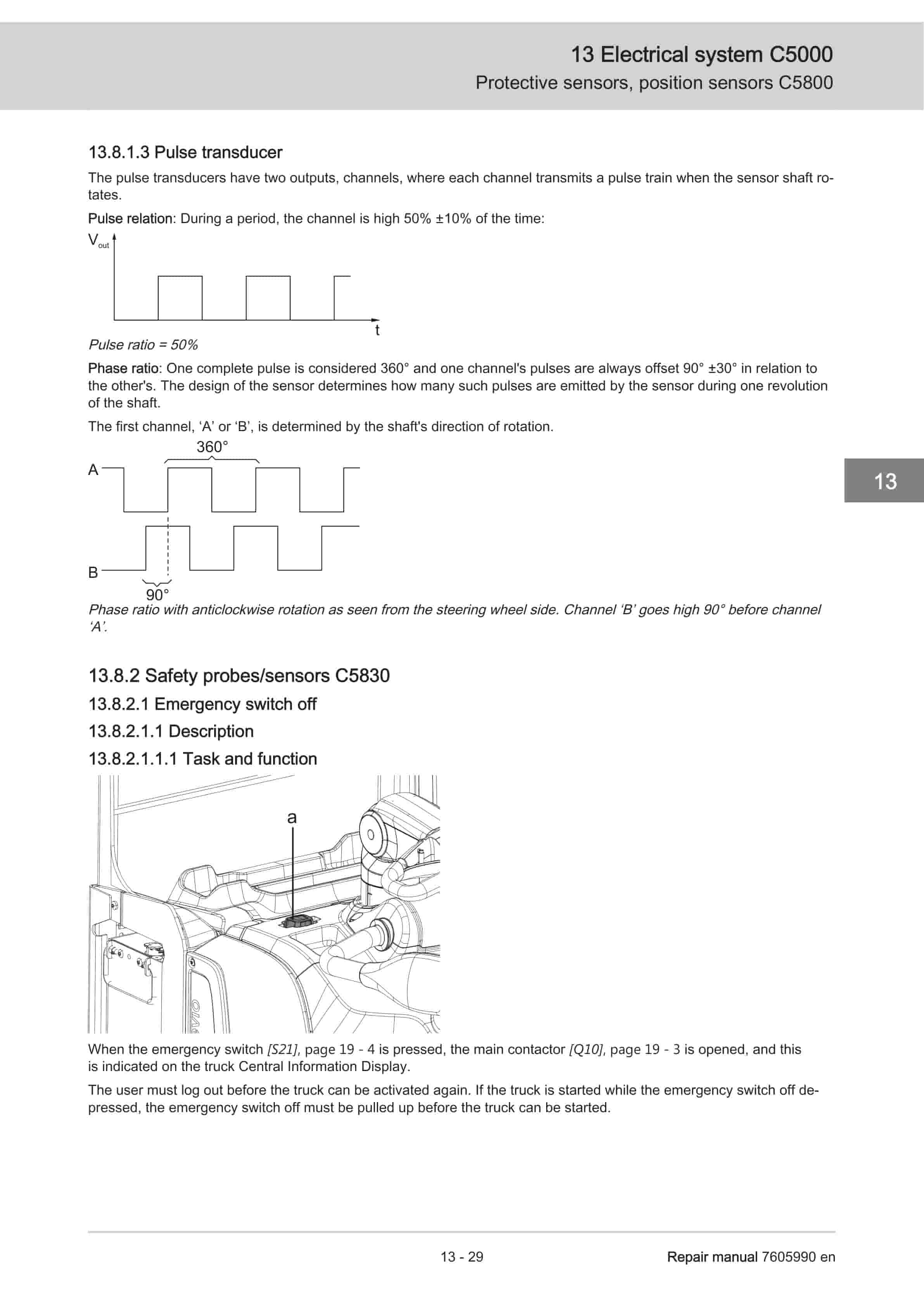
- 13.8. Protective sensors, position sensors C5800
- 13.8.1. Description
- 13.8.2. Safety probes/sensors C5830
- 13.9. Calibrations
- 13.9.1. Steering angle calibration
- 13.9.2. Hydraulic valve calibration
- 13.9.3. Pressure sensor calibration
- 14. Hydraulics/Pneumatics C6000
- 14.1. Overview
- 14.2. Description
- 14.2.1. Hydraulic hygiene
- 14.2.2. Erroneous hydraulic system pressure
- 14.3. Quick change connectors
- 14.3.1. Overview quick change connectors
- 14.3.2. Removing female quick change connectors
- 14.3.3. Installing female quick change connectors
- 14.3.4. Removing a quick change connector (male)
- 14.3.5. Installing a quick change connector (male)
- 14.4. Hydraulic unit C6100
- 14.4.1. Description
- 14.4.2. Hydraulic oil tank C6110
- 14.4.3. Filter, filter housing C6130
- 14.4.4.
- 14.4.5. Replacing the valve coil
- 14.4.6. Replacing the pressure sensor
- 14.5. Hydraulic system, fitted on the mast C6300
- 14.5.1. Mast hydraulic conduits C6320
- 14.6. Hydraulic cylinder C6600
- 14.6.1. Main lift cylinders C6610
- 14.6.2. Reach/telescoping cylinder C6650
- 15. Work function – lifting masts C7000
- 15.1. Description
- 15.1.1. Ordering a replacement mast
- 15.2. Chain system, general
- 15.2.1. General
- 15.2.2. Adjusting the chain
- 15.2.3. Lubrication
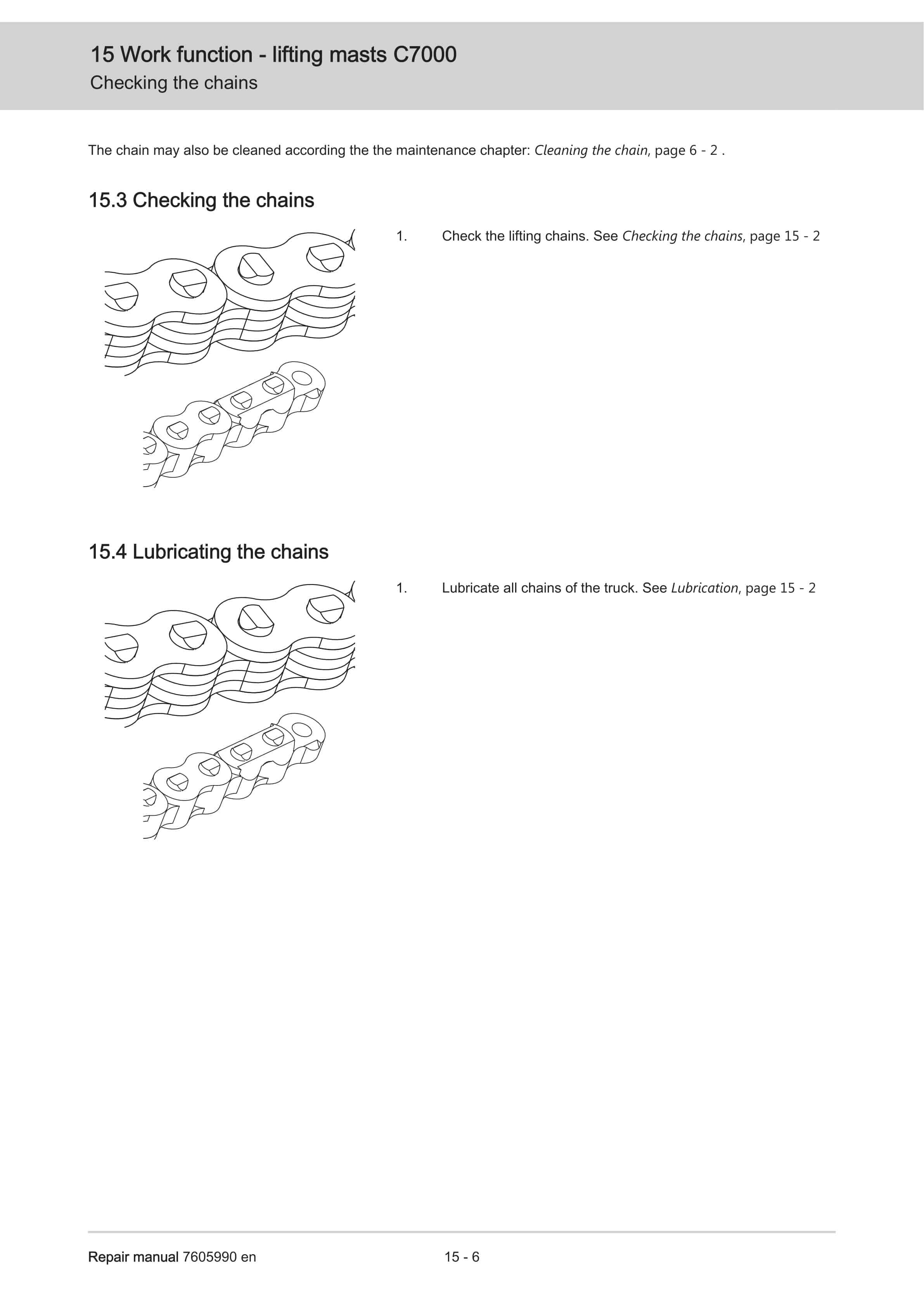
- 15.2.4. Checking the chains
- 15.3. Checking the chains
- 15.4. Lubricating the chains
- 15.5. Checking the split pins
- 15.6. Check-tighten the locking nuts
- 15.7. Main mast C7100
- 15.7.1. Check for cracks/damages to the mast
- 15.7.2. Checking the 1.8 meter sensor
- 15.7.3. Lubrication of the mast roller guides
- 15.7.4. Adjusting the slide pad
- 15.7.5. Adjusting the slide pad
- 15.7.6. Replacement of the mast
- 15.7.7. Main mast suspension C7190
- 15.8. Auxiliary mast/mast C7200
- 15.8.1. Replacing the auxiliary mast
- 15.8.2. Auxiliary mast struts C7210
- 15.8.3. Auxiliary mast yoke carriage C7230
- 15.9. Lifting/carrying/clamping devices C7400
- 15.9.1. Fork carriage unit/with integrated sideshift/fork spread C7420
- 16. Auxiliary equipment, installation equipment C8000
- 17. Optional equipment/Extra equipment C9000
- 17.1. Overview
- 17.2. Extra electrical equipment C9400
- 17.2.1. Extra power socket
- 17.2.2. Truck log equipment, code lock C9420
- 17.3. Other extra equipment C9500
- 17.3.1. Ground strap
- 17.3.2. Fire extinguisher
- 17.3.3. Horizontal E-bar
- 17.3.4. Spider expansion unit
- 18. Instructions for disposal
- 18.1. General
- 18.2. Marking of plastics
- 18.2.1. General marking of products and packaging
- 18.2.2. Marking according to the manufacturers standards
- 18.3. Pressure vessels
- 18.3.1. Gas struts
- 18.4. Sorting categories
- 19. Wiring diagram
- 19.1. Colour code table
- 19.2. Diagram
- 19.2.1. Component list
- 19.2.2. Explanation S112-115, the functions controlled by the switch depend on what options the truck is fitted with.
- 19.2.3. Component placement
- 19.2.4. General diagram
- 19.2.5. Detailed diagrams
- 20. Hydraulics schematics
- 20.1. List of symbols
- 20.2. Diagram
- 20.2.1. Component list
- 20.2.2. Component placement
- 20.2.3. Detailed diagrams
- 20.3. Diagram
- 20.3.1. Component list
- 20.3.2. Component placement
- 20.3.3. Detailed diagrams
- 21. Tools
- 21.1. Tools for electric connectors
- 21.1.1. AMP connectors
- 21.1.2. MQS connectors
- 21.1.3. CPC connectors
- 21.1.4. AMP Seal connectors
- 21.2. Special tools
- 22. Service data and grease specifications
- 22.1. General tightening torques
- 22.1.1. Galvanised, non-oiled screws
- 22.1.2. Untreated, oiled screws
- 22.2. Lubricants specification
- 23. Technical data
- 23.1. Truck Dimensions
- 23.2. Truck Dimensions
- 23.3. Truck data
- 24. Index
Related products
-
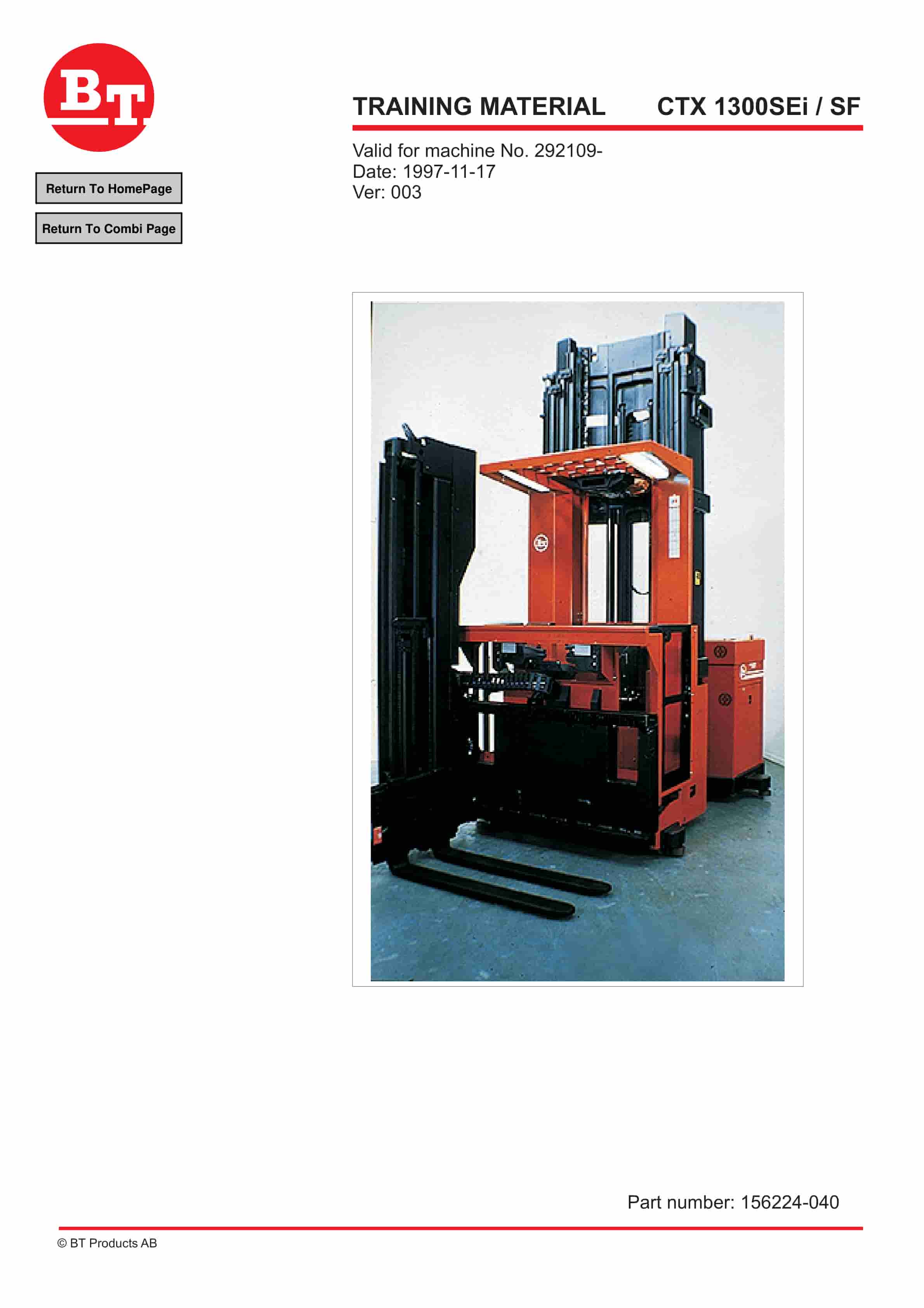
BT CTX 1300SEi, CTX 1300SEi SF Training Material 156224-040
$30.00 Add to cart -
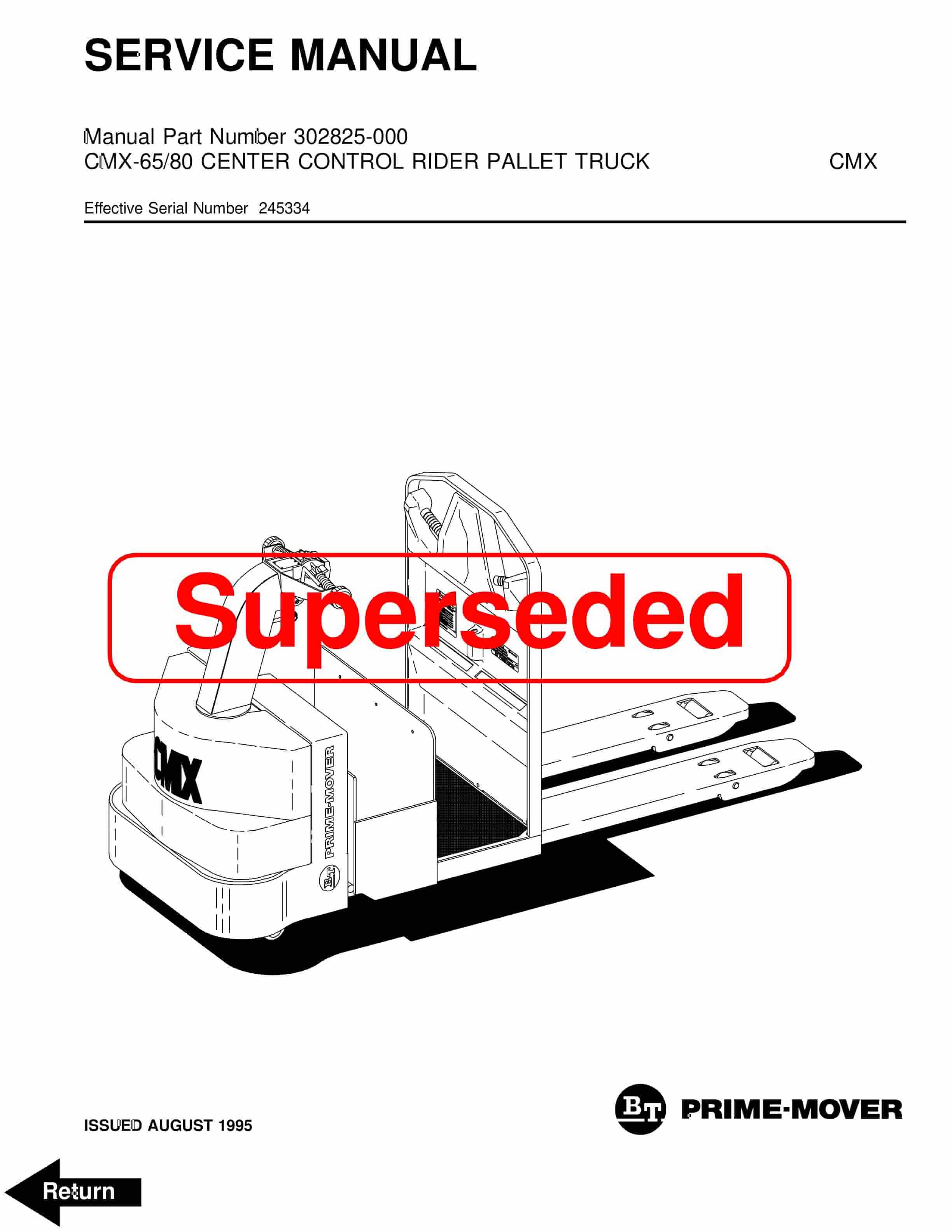
BT CMX-65, CMX-80 Center Control Riding Pallet Truck Service Manual 302825-000
$30.00 Add to cart -
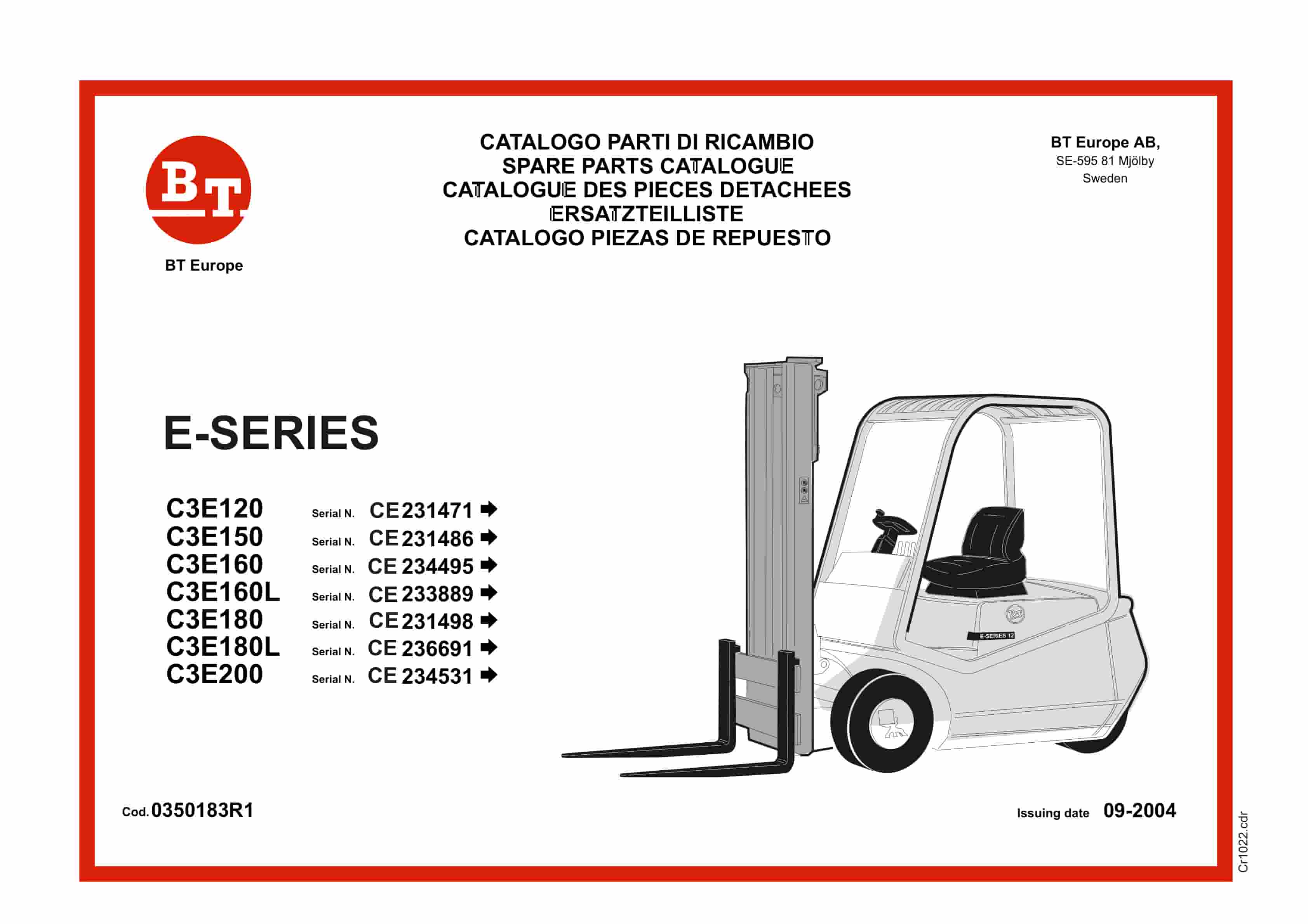
BT E-Series C3E120 to C3E200 Service Manual 0350183R1
$30.00 Add to cart -
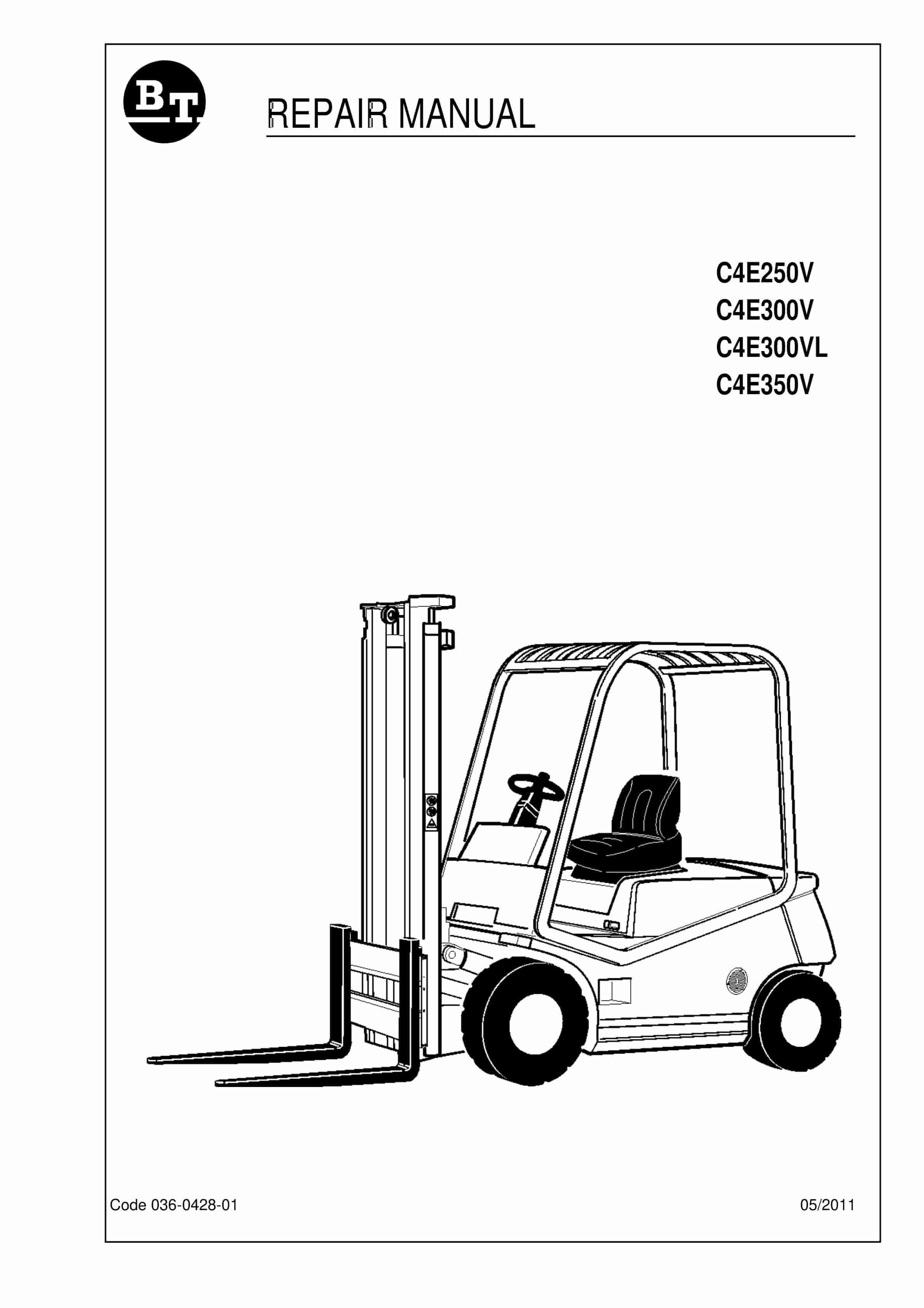
BT C4E250V, C4E300V, C4E300VL, C4E350V Repair Manual 036-0428-01
$30.00 Add to cart -
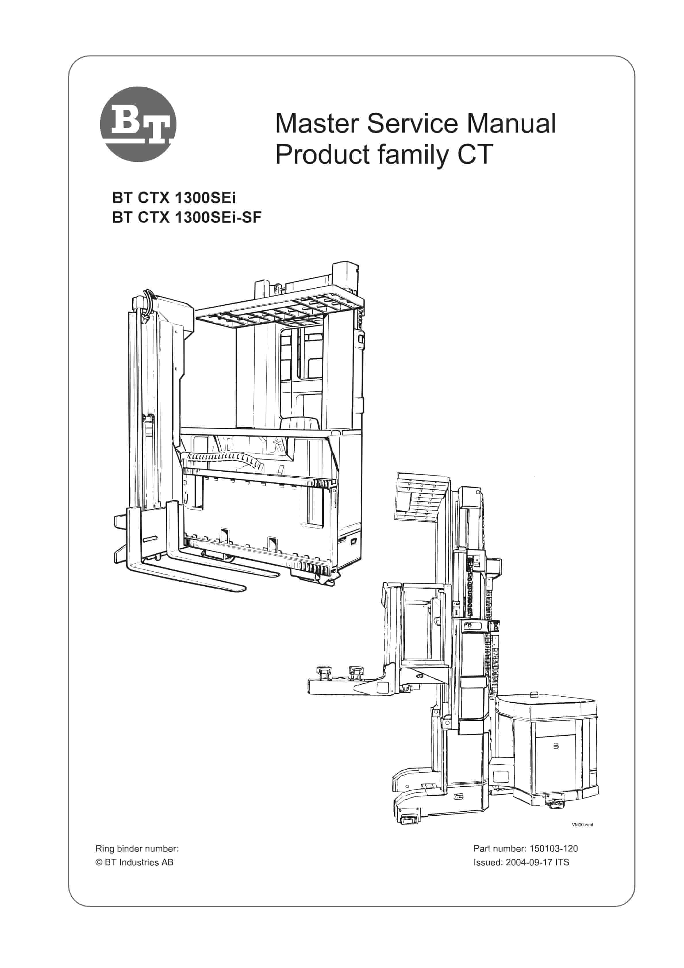
BT CTX 1300SEi, CTX 1300SEi SF Service Manual 150103-120
$30.00 Add to cart


