

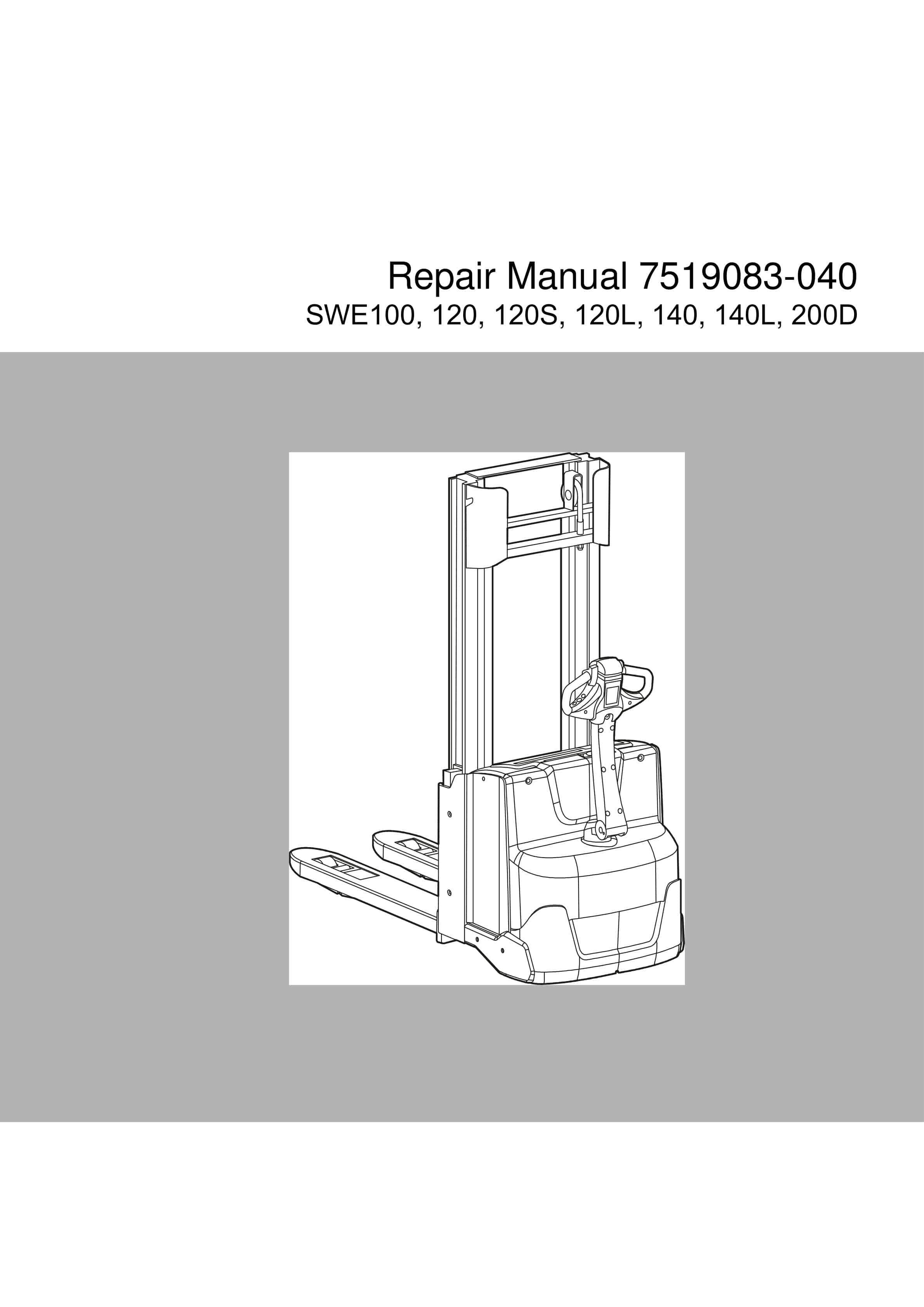
BT SWE100, SWE120, SWE120L, SWE120S, SWE140, SWE140L, SWE200D Repair Manual 7519083-040
$30.00
- Type Of Manual: Repair Manual
- Manual ID: 7519083-040
- : Service Manual PDF
- Number of Pages: 246
- Size: 20.1MB
- Format: PDF
Product details
-
Model List:
- SWE100, SWE120, SWE120L, SWE120S, SWE140, SWE140L, SWE200D
- 1. Contents
- 2. General introduction
- 2.1. How to use this manual
- 2.2. Warning symbols
- 2.3. Pictograms
- 2.3.1. Screws/Nuts
- 3. General safety rules
- 3.1. Work safety
- 3.2. Electrical system
- 3.3. Safe lifting
- 3.4. Truck modifications
- 4. Installation
- 4.1. General
- 4.2. Transporting the truck
- 4.3. Transporting the mast
- 4.4. Safe lifting
- 4.5. Battery installation
- 4.5.1. Safety when handling batteries
- 4.5.2. Installing the battery
- 4.6. Programming PIN codes
- 4.6.1. PIN code standard
- 4.7. Setting parameters
- 4.7.1. Setting the parameters for collision sensor (option)
- 4.7.1.1. Collision sensor parameters 105, 106 and 111
- 4.7.1.2. Programming the PIN code for resetting the truck
- 4.7.2. Setting the parameters for the battery and the battery charger
- 4.7.3. Parameter 107 Battery size
- 4.7.3.1. Verifying the parameter setting for freely ventilated batteries (Lead-acid batteries)
- 4.7.3.2. Verifying the parameter setting for valve-regulated batteries (Hawker/Exide)
- 4.8. Function and safety checks
- 5. Maintenance
- 5.1. Introduction
- 5.2. Maintenance instructions
- 5.2.1. Cleaning and washing
- 5.2.2. High-pressure washers
- 5.2.3. Degreasing agents
- 5.2.4. Cleaning the exterior
- 5.2.5. Cleaning the chain
- 5.2.6. Cleaning the motor compartment
- 5.2.7. Electric components
- 5.3. General
- 5.4. Service intervals
- 5.5. Maintenance schedule
- 6. Function and parameters
- 6.1. General
- 6.2. Description of the function
- 6.2.1. Symbols on keypad and display
- 6.3. Operating principle
- 6.4. Hour meter
- 6.5. Parameters
- 6.5.1. General
- 6.5.2. Displaying parameters
- 6.5.3. Setting parameters
- 6.5.4. Operator parameters
- 6.5.4.1. Factory preset operator parameters
- 6.5.5. Service parameters
- 6.5.6. Factory parameters
- 6.5.6.1. Matrix for hardware/software compatibility
- 7. Troubleshooting
- 7.1. General
- 7.1.1. Software compatibility
- 7.2. Emergency driving mode
- 7.3. Towing a defective truck
- 7.3.1. Tow using a tow truck and tow wagon
- 7.4. Troubleshooting methods
- 7.4.1. General initial troubleshooting
- 7.4.2. Concluding troubleshooting
- 7.5. Error code history
- 7.6. Error code system
- 7.7. Error codes
- 7.8. Troubleshooting chart
- 7.8.1. The truck cannot be driven.
- 7.8.2. Truck only travels at reduced speed
- 7.8.3. The truck can be driven but behaves abnormally
- 7.8.4. The truck can be driven, but some functions do not work
- 7.8.4.1. Software compatibility
- 7.8.4.2. Hardware compatibility matrix
- 7.8.5. Defective hydraulic functions
- 7.9. Built-in test function
- 7.10. Digital input/output status
- 7.10.1. Test function 9 Transistor regulator
- 7.10.2. Test function 10 Logic card
- 7.10.3. Test function 12 Expansion unit SEU (option).
- 7.11. Test function for the display
- 7.12. Checking the built-in battery charger
- 8. Chassis 0000
- 8.1. Support arm 0350
- 8.1.1. Support arm lift, lateral adjustment
- 8.1.2. Adjusting the kneeling action
- 8.2. Motor mounts 0450
- 8.2.1. Replacing springs (not applicable for S212S)
- 8.3. Removing the platform
- 9. Electric drive motor 1700
- 9.1. Components
- 9.2. Removing the motor from the truck
- 9.3. Drive motor tightening torques
- 9.4. Installing the temperature sensor
- 9.5. Cleaning
- 10. Drive gear 2550
- 10.1. General
- 10.2. Components
- 10.3. Removing the gear from the truck (not applicable for S212S)
- 10.4. Removing the gear from the truck (not applicable for S212S)
- 10.5. Replacing the wheel hub seal
- 10.5.1. Removing the seal
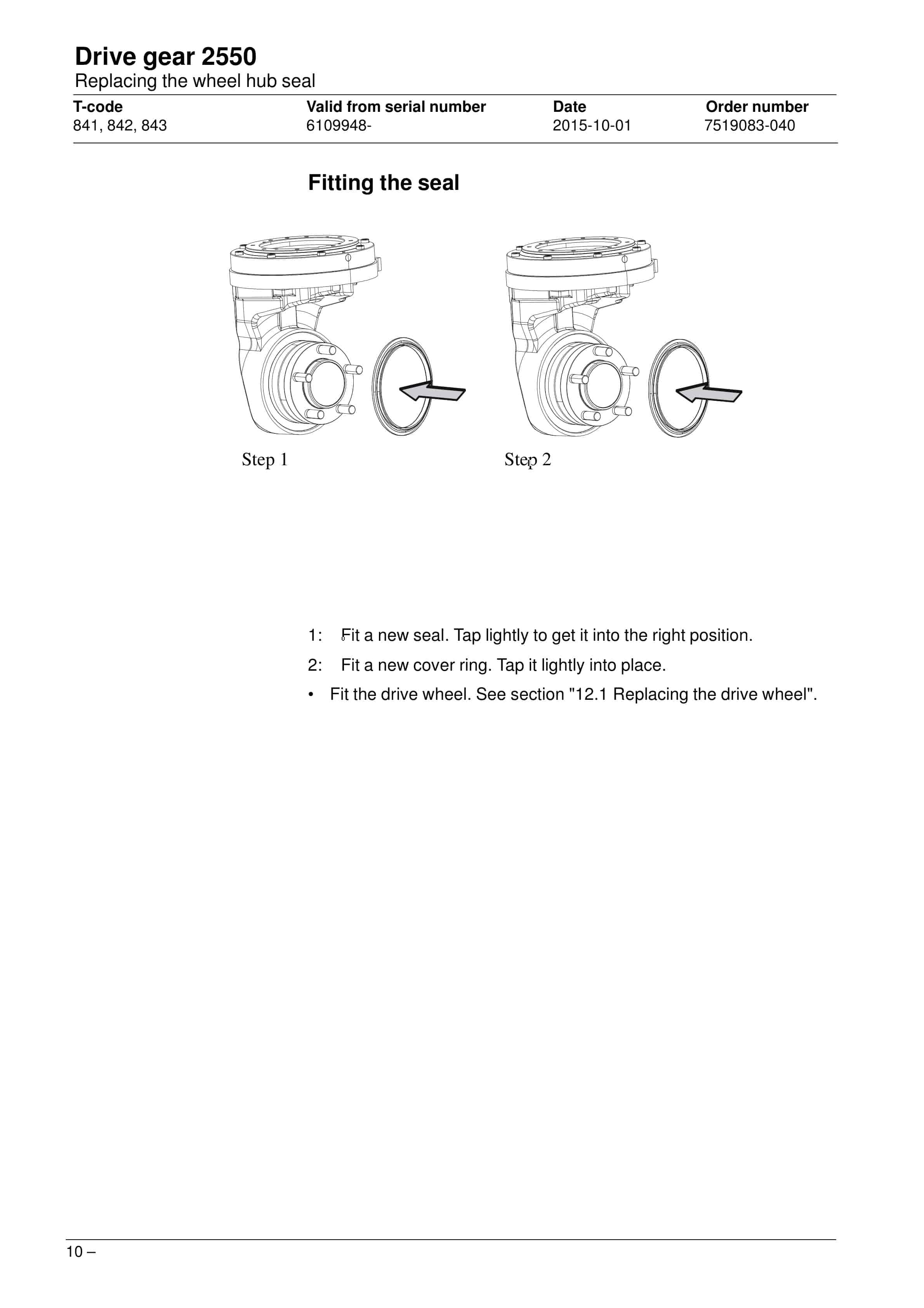
- 10.5.2. Fitting the seal
- 11. Brakes 3180
- 11.1. Components
- 11.2. Releasing the brake
- 11.3. Installing the dust shield
- 11.4. Installing the dust shield
- 12. Drive wheel 3530
- 12.1. Replacing the drive wheel
- 13. Castor wheels 3540
- 13.1. Components
- 13.2. Castor wheel mounting
- 13.3. Replacing the castor wheel
- 14. Support arm wheel 3550
- 15. Tiller arm 4000
- 15.1. Tiller arm components
- 15.2. Removing the tiller arm
- 15.3. Replacing the gas spring
- 15.4. Replacing the safety sensor
- 15.4.1. Dismantling
- 15.4.2. Fitting
- 15.5. Electrical steering system 4000
- 15.5.1. Tiller arm handle C4110
- 15.5.2. Components of the tiller arm handle (new design)
- 15.5.3. Components of the tiller arm handle (old design)
- 15.5.4. Replacing the signal button/switch
- 15.5.5. Replacement of lift/lower button
- 15.5.6. Replacing the button
- 15.5.7. Changing the position of the controls – support arm lift/fork lift
- 15.5.8. Replacing the safety reversal switch
- 16. Electric components
- 16.1. Replacing the wiring harness
- 16.1.1. Replacing the transistor regulator wiring harness
- 16.2. Replacing the transistor regulator
- 17. Hydraulic system 6000
- 17.1. General
- 17.2. Hydraulic hygiene
- 17.2.1. Washing
- 17.2.2. Packaging
- 17.2.3. Handling
- 17.2.4. Storage
- 17.2.5. Work procedures
- 17.3. Hydraulic unit 6100
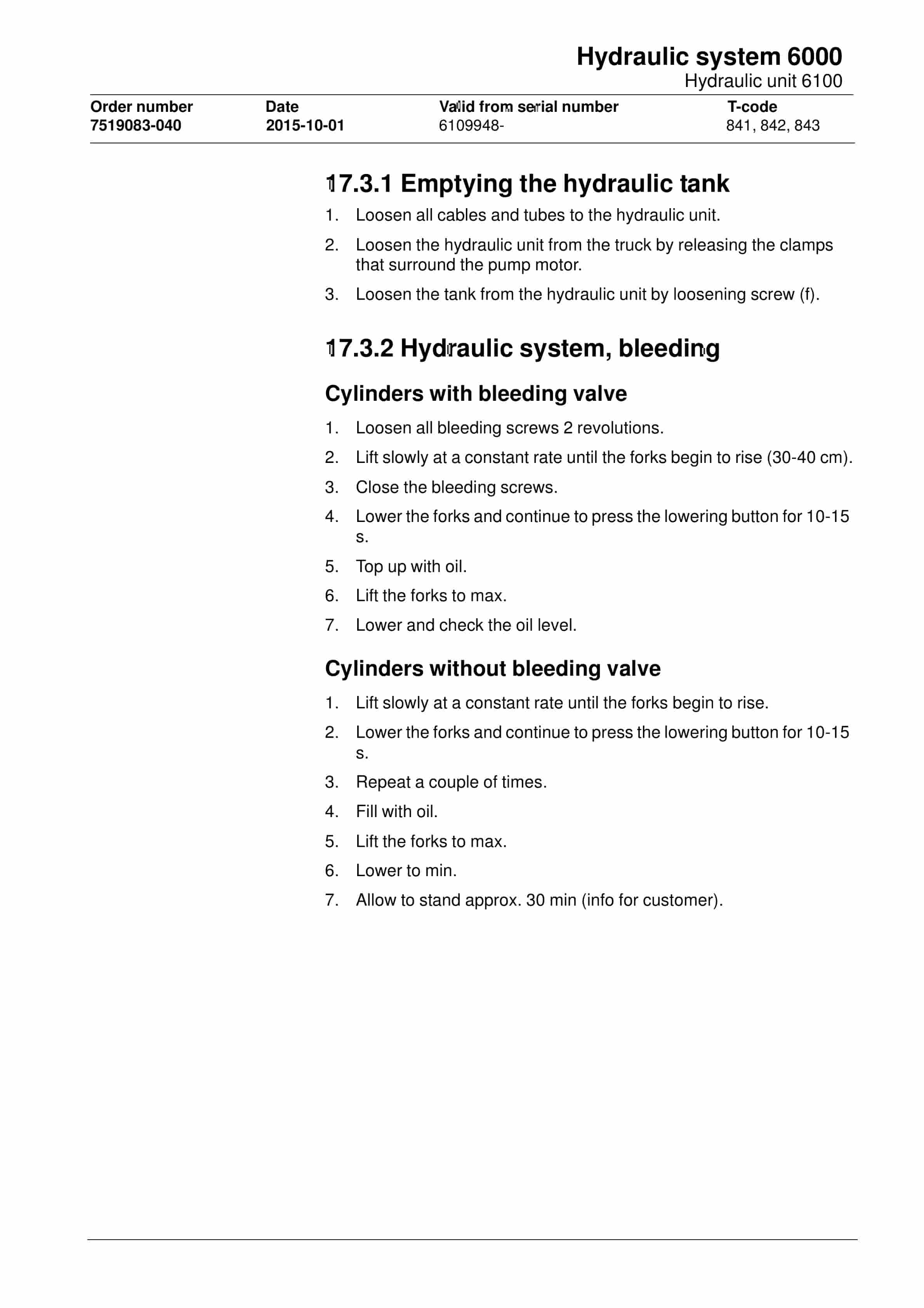
- 17.3.1. Emptying the hydraulic tank
- 17.3.2. Hydraulic system, bleeding
- 17.3.2.1. Cylinders with bleeding valve
- 17.3.2.2. Cylinders without bleeding valve
- 17.4. Hydraulic connections 6230
- 17.4.1. Quick change connector
- 17.4.1.1. Connecting the quick change connector
- 17.4.1.2. Dismantling the quick change connector
- 17.5. Hydraulic calibration
- 17.6. Adjusting the pressure limiting valve
- 17.7. Disassembling the hydraulic unit
- 17.8. Hydraulic unit tightening torques
- 18. Lift mast 7000
- 18.1. Main mast 7100
- 18.1.1. Components
- 18.1.2. Maintenance
- 18.1.2.1. Fixing point
- 18.1.2.2. Lubrication
- 18.2. Fork carriage 7420
- 18.2.1. Maintenance
- 18.3. Main lift chain system 7120
- 18.3.1. Checking the chain setting
- 18.3.2. Checking the chain
- 18.3.2.1. Surface rust
- 18.3.2.2. Rusty links
- 18.3.2.3. Stiff links
- 18.3.2.4. Bolt rotation
- 18.3.2.5. Loose bolts
- 18.3.2.6. Outline wear
- 18.3.2.7. Stretching
- 18.3.2.8. Damaged plates
- 18.3.2.9. Damaged bolts
- 18.3.2.10. Dirty chain
- 18.3.3. Cleaning
- 18.3.4. Lubrication
- 18.3.5. Adjustment
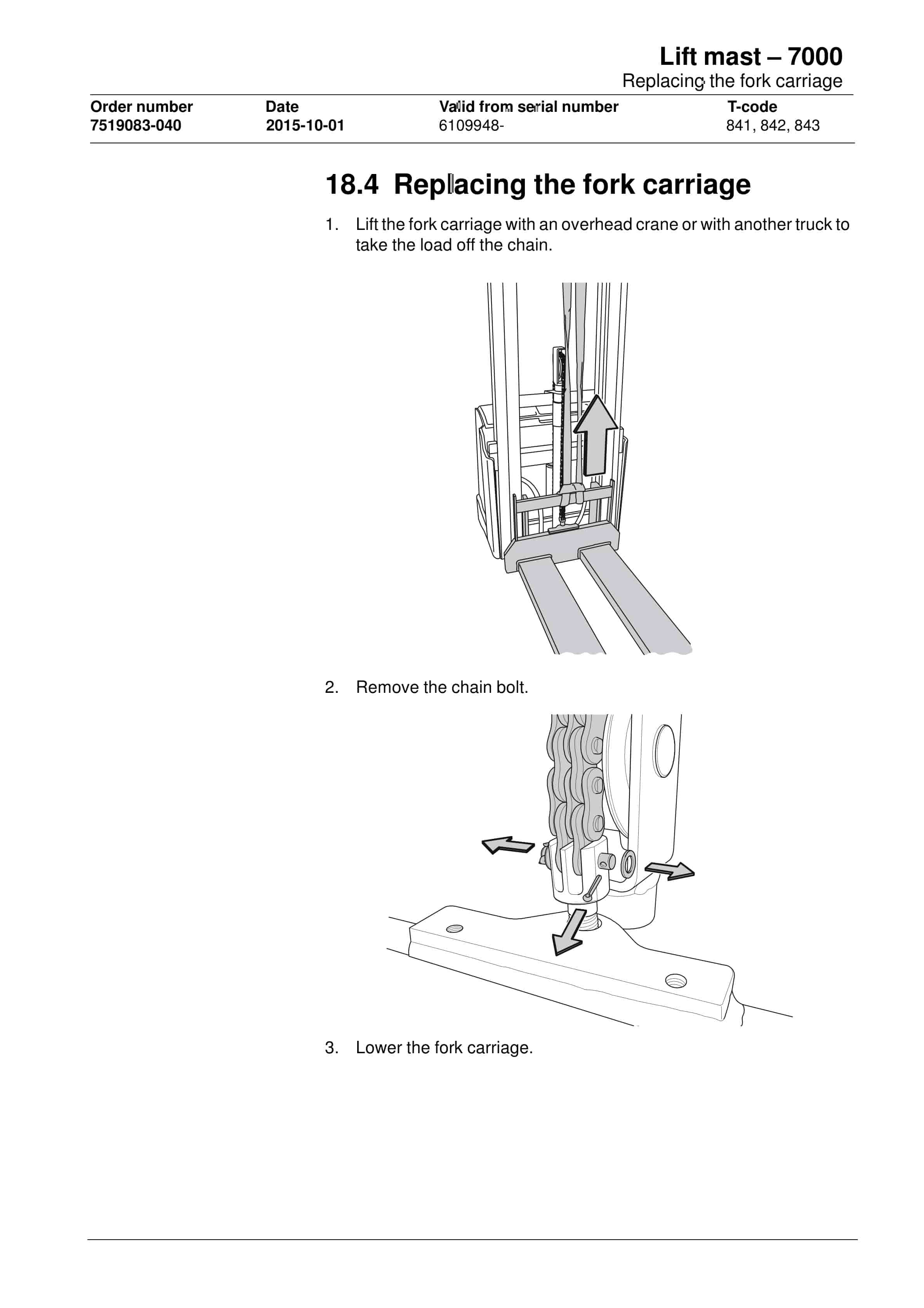
- 18.4. Replacing the fork carriage
- 18.5. Replacement of the mast
- 18.6. Adjusting the mast
- 19. Accessories
- 19.1. Spider expansion unit
- 19.2. TLS – Truck log system
- 19.3. ID unit
- 19.4. Built-in battery charger
- 19.4.1. Technical data
- 19.4.2. Charging the battery
- 19.4.2.1. Main charging
- 19.4.2.2. Equalising charging
- 19.4.2.3. Charging completed
- 20. Attachments
- 20.1. General
- 21. Technical data
- 21.1. S210, S212, S214
- 21.2. S212L, S214L, S220D
- 21.3. S212S
- 21.4. Overflow pressure for mast
- 22. General tightening torques
- 22.1. General
- 22.2. Galvanised, non-oiled screws
- 22.3. Untreated, oiled bolts
- 23. Tools
- 23.1. MQS contacts
- 23.2. AMP connectors
- 23.2.1. AMP connectors, Multilock series 040
- 23.3. Molex connectors
- 23.4. Grease guns
- 23.5. Other tools
- 24. Oil and grease specification
- 25. Electrical components and wiring diagram
- 25.1. Electric components
- 25.2. Wiring diagram
- 25.2.1. List of symbols
- 25.2.2. General wiring diagram
- 25.2.3. Wiring diagram
- 26. Hydraulics chart
- 27. Instructions for disposal
- 27.1. General
- 27.2. Marking of plastics
- 27.2.1. General marking of products and packaging
- 27.2.2. Marking according to standard
- 27.2.2.1. Abbreviations
- 27.2.2.2. Marking examples
- 27.3. Pressure vessels
- 27.3.1. Gas struts
- 27.4. Sorting categories
Related products
-
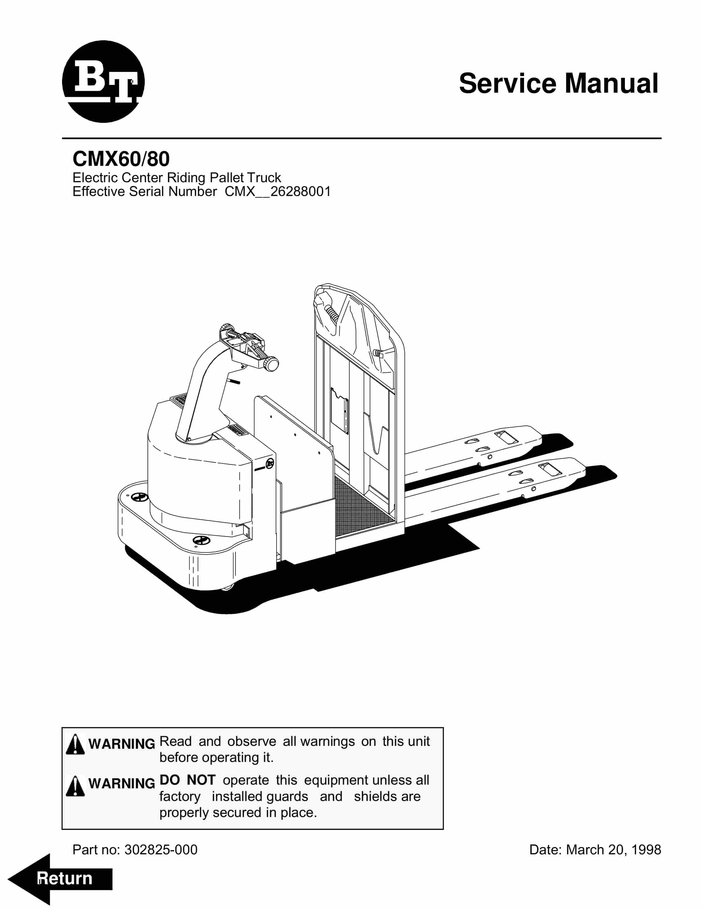
BT CMX60, CMX80 Electric Center Riding Pallet Truck Service Manual 302825-000
$30.00 Add to cart -
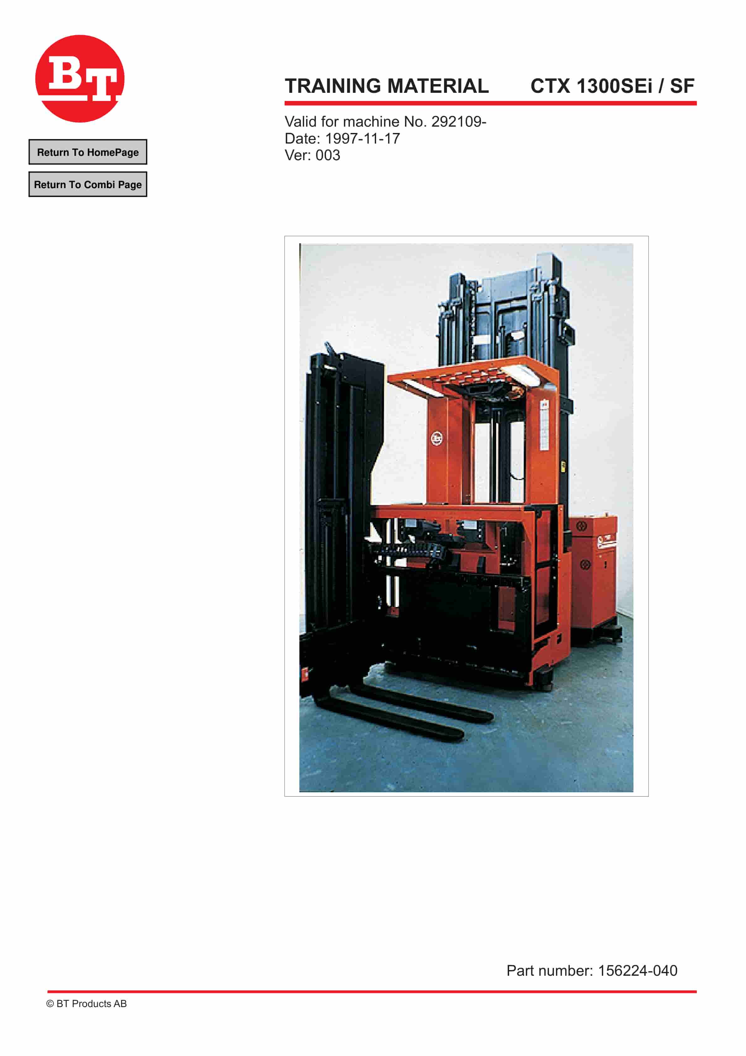
BT CTX 1300SEi, CTX 1300SEi SF Training Material 156224-040
$30.00 Add to cart -
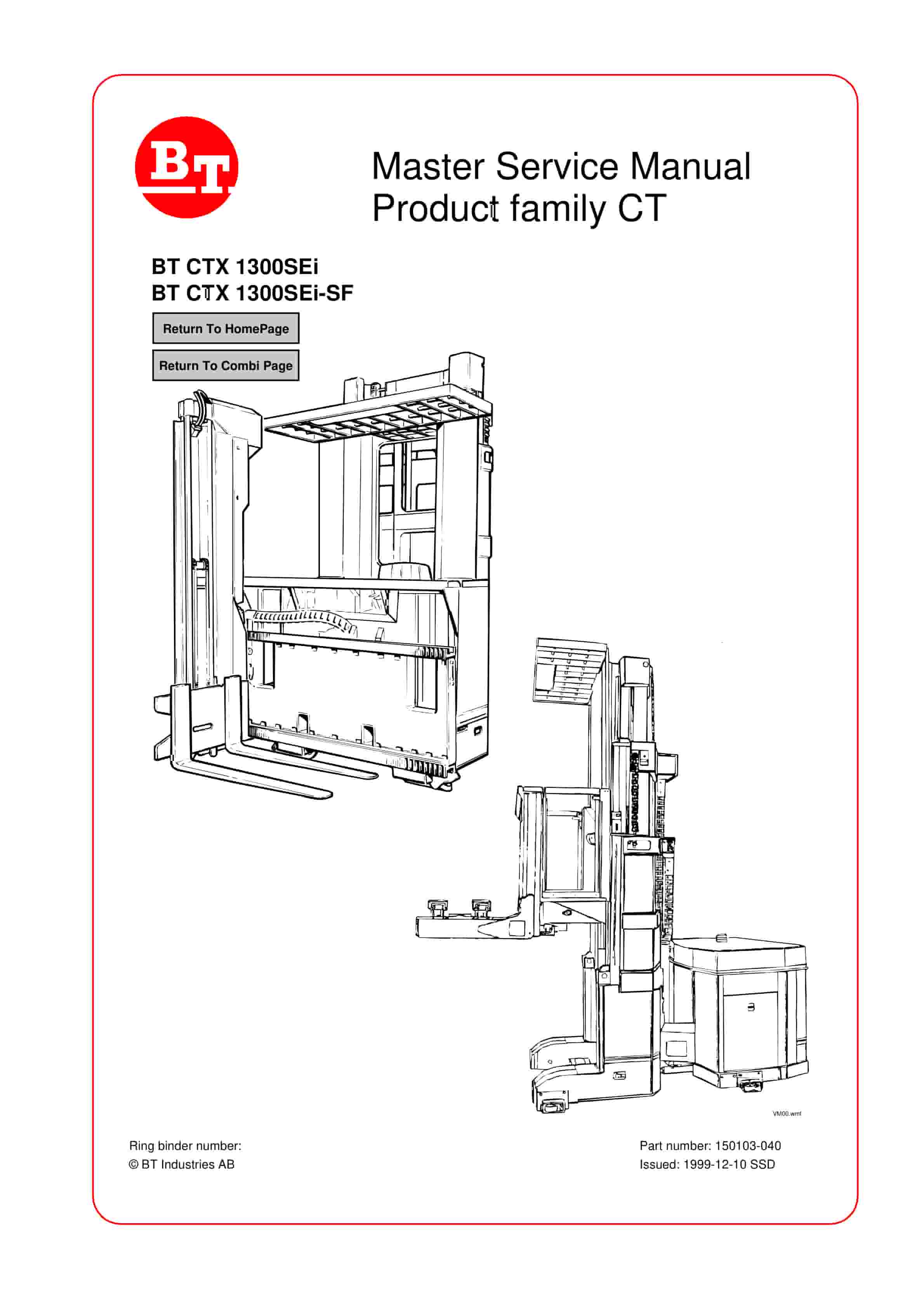
BT CTX 1300SEi, CTX 1300SEi SF Service Manual 150103-040
$30.00 Add to cart -
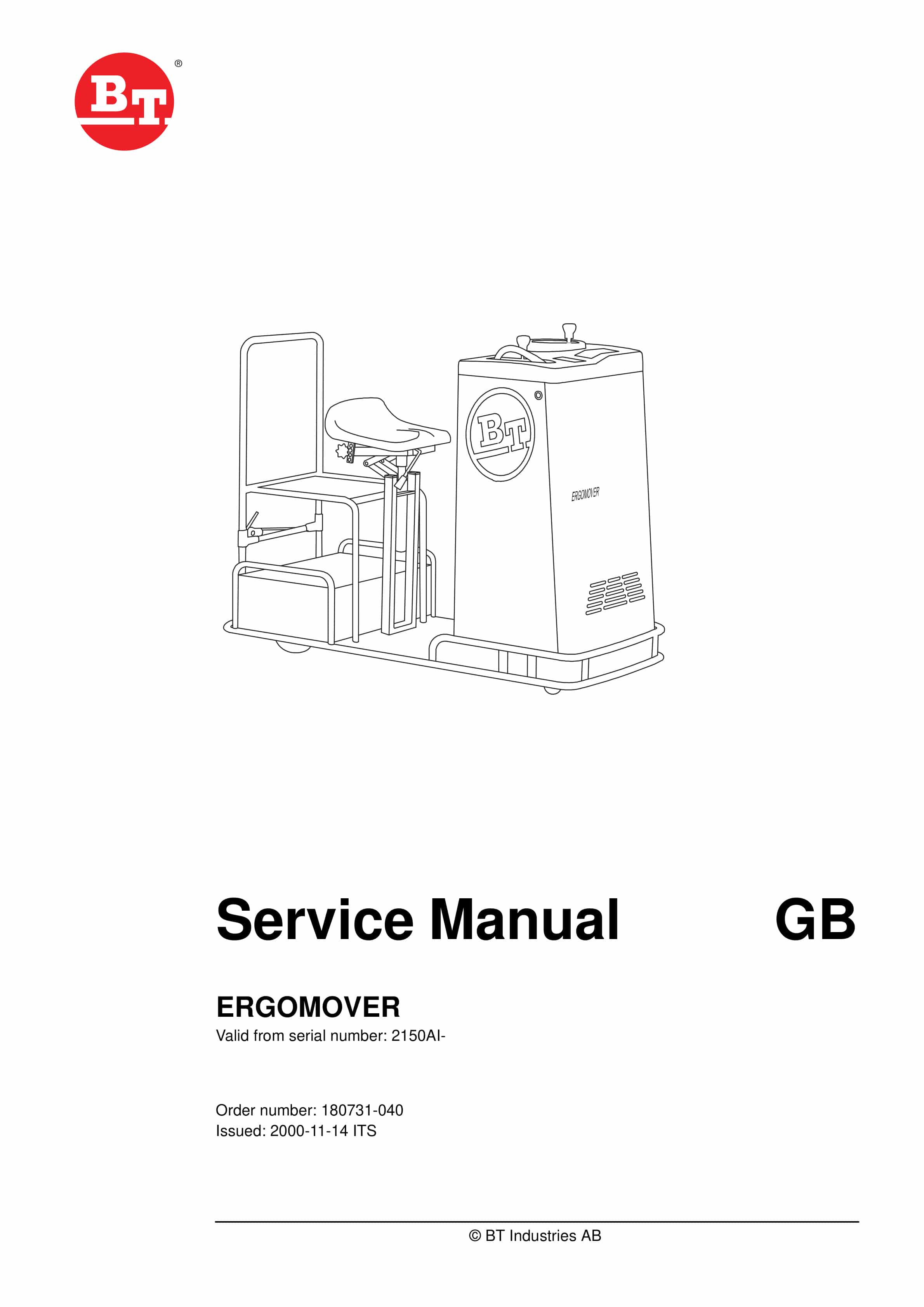
BT ERGOMOVER Service Manual 180731-040
$30.00 Add to cart -
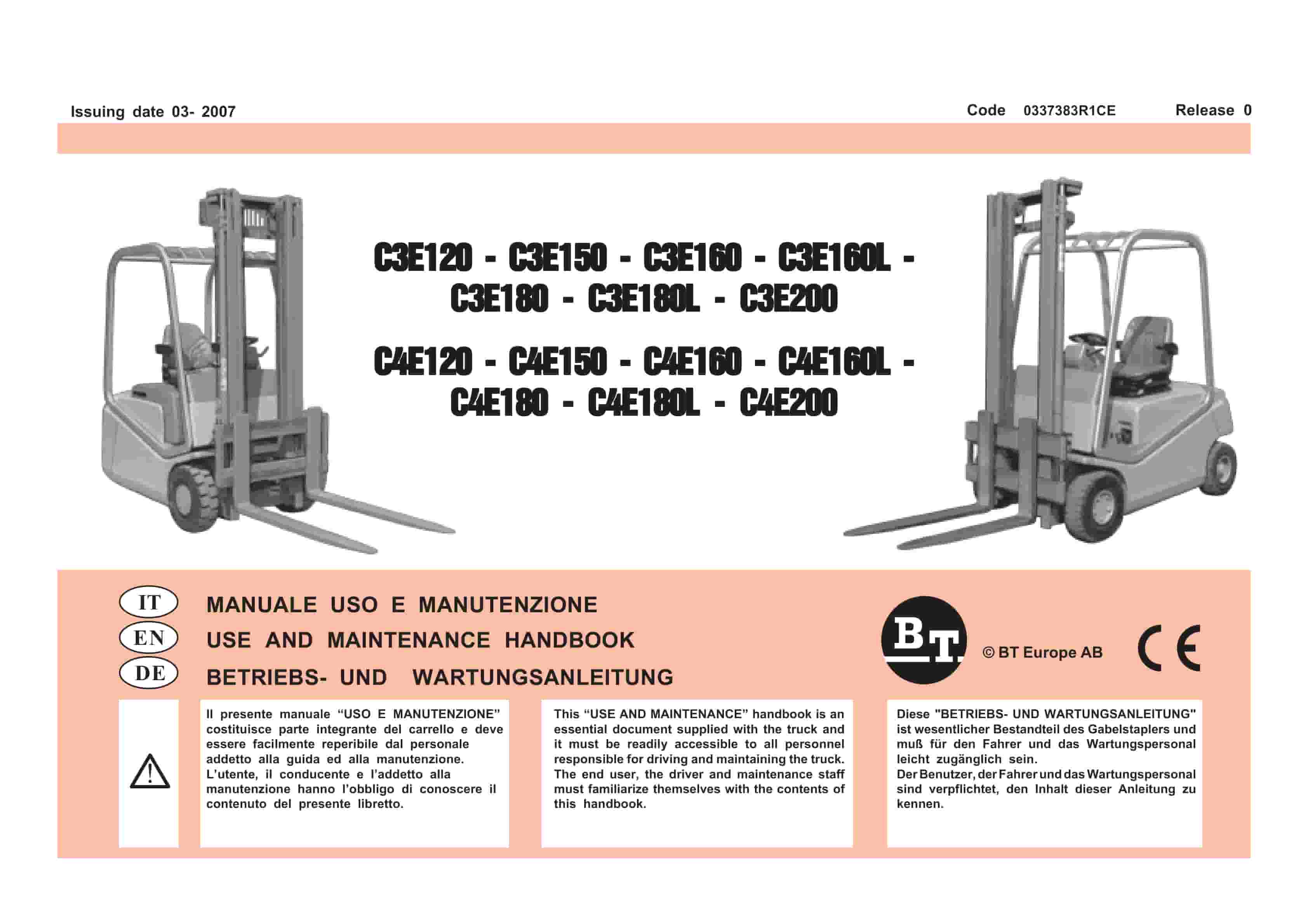
BT C3E120 to C4E200 Use And Maintenance Handbook 0337383R1CE
$30.00 Add to cart


