No products in the cart.
Return to shop
$44.00
Linkbelt
Linkbelt 800LX Excavator Service Repair Manual
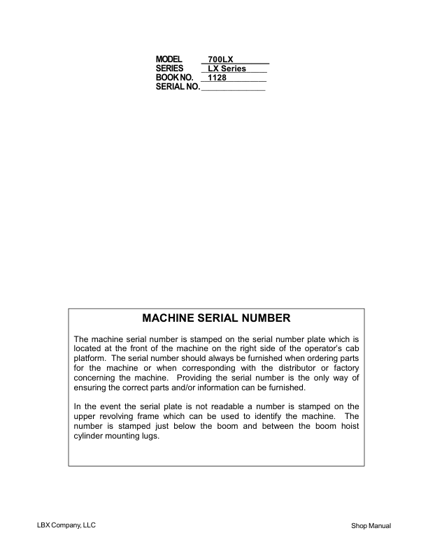
Linkbelt 700LX (Tier 3) Excavator Service Repair Manual
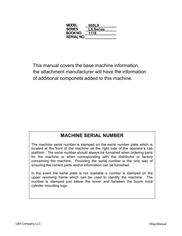
Linkbelt 600LX, 600LX MH (Tier 3) Excavator Service Repair Manual
Linkbelt LS 4300 C2 Excavator Service Repair Manual
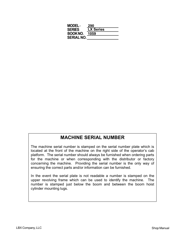
Linkbelt 290LX Excavator Service Repair Manual
Linkbelt 600LX, 600LX MH Excavator Service Repair Manual
Linkbelt LS 4300 C2 Hydraulic Log Loader Repair Manual
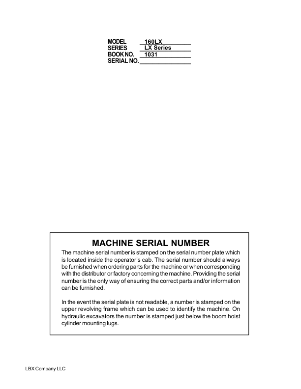
Linkbelt 160LX Excavator Service Repair Manual
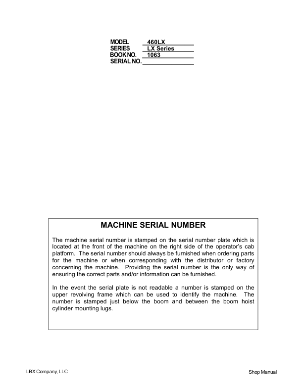
Linkbelt 460LX Excavator Service Repair Manual
Linkbelt LS-3400 C2 Excavator Service Repair Manual
 Excavator Service Repair Manual 1")
 Excavator Service Repair Manual 2")
 Excavator Service Repair Manual 3")
 Excavator Service Repair Manual 4")