

BT PPT1400, PPT1600, PPT2000, PPL2000 Service Manual 147637-040
$30.00
- Type Of Manual: Service Manual
- Manual ID: 147637-040
- : Service Manual PDF
- Number of Pages: 204
- Size: 12.3MB
- Format: PDF
Product details
-
Model List:
- PPT1400, PPT1600, PPT2000, PPL2000
- 1. Return To Homepage
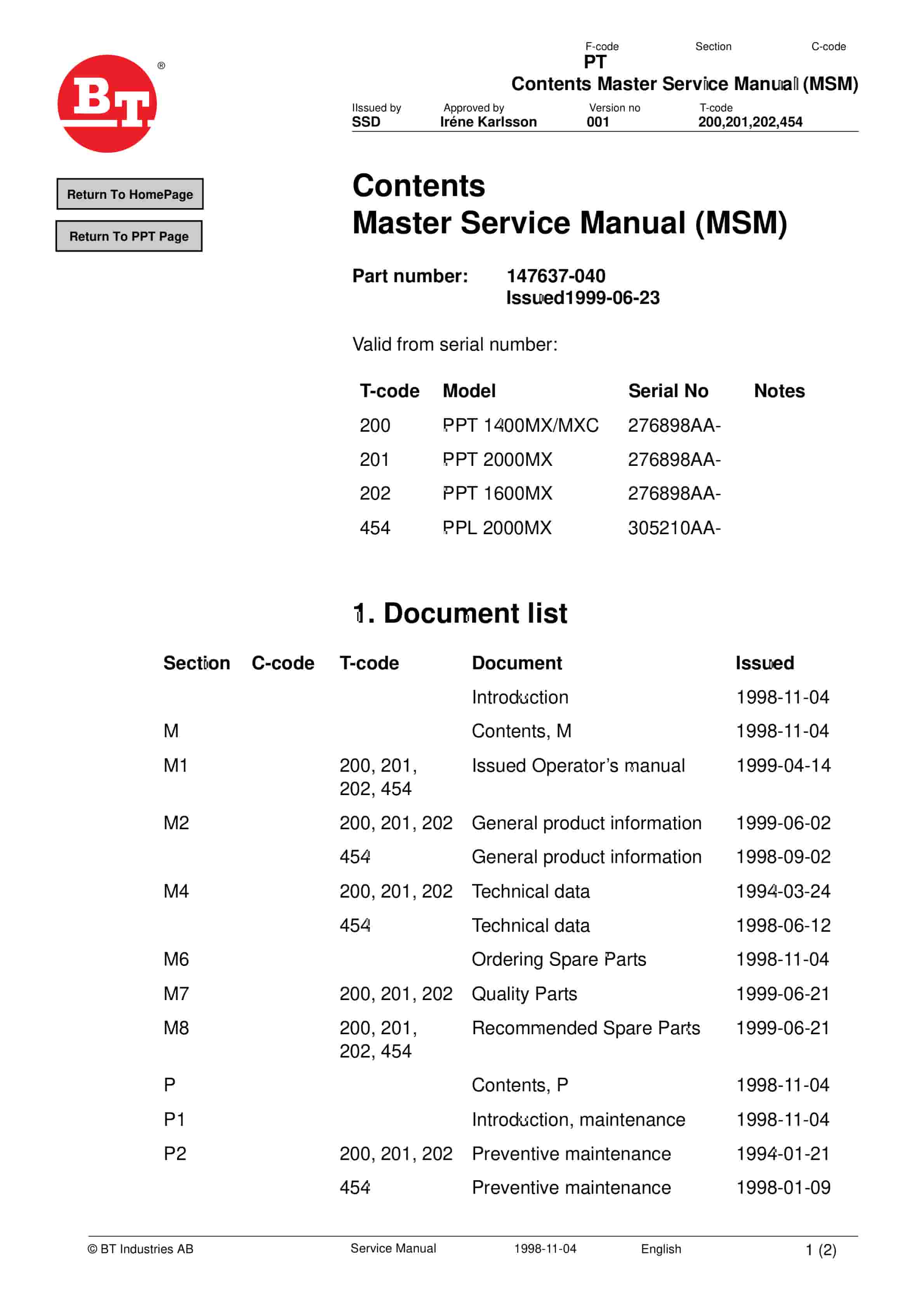
- 2. Contents Master Service Manual (MSM)
- 2.1. Valid from serial number
- 2.2. Serial No
- 2.3. Document list
- 2.3.1. Section
- 2.3.2. Document
- 3. Introduction to BTs Service Manual
- 4. Contents, M
- 4.1. Truck information
- 5. Operators manual
- 5.1. Valid from serial number
- 5.2. Serial No
- 5.3. General
- 5.3.1. Issued operators manuals
- 6. General product information
- 6.1. Valid from serial number
- 6.1.1. Serial No
- 6.2. Presentation of the truck
- 6.2.1. Intended application of the truck
- 6.2.2. Forbidden application of the truck
- 6.3. Truck data
- 6.3.1. Truck type
- 6.3.2. PPT 1400MX
- 6.3.3. PPT 1400C
- 6.3.4. PPT 1600MX
- 6.3.5. PPT 2000MX
- 6.4. Truck dimensions
- 6.4.1. PPT 1400, 1600 2000MX
- 6.4.2. PPT 1400C
- 6.4.3. PPT 1400MX
- 6.4.4. PPT 1600MX
- 6.4.5. PPT 2000MX
- 6.5. Identification plate
- 6.6. Modification plate
- 6.7. Main components
- 6.7.1. Tiller arm The truck is manoeuvred by the driver while walking. 208 degree steering area. The…
- 6.7.2. Covers Removable which provides good accessibility when servicing.
- 6.7.3. Emergency disconnector and battery connector The battery is charged via the permanently fitte…
- 6.7.4. Hydraulic unit Pump motor and pump are integrated in a compact unit.
- 6.7.5. Drive unit with brake Fixed drive unit with spring-loaded mechanical brake, travel motor, gea…
- 6.7.6. Serial number The serial number plate fitted to the chassis.
- 6.7.7. Support castor wheels Two support castor wheels to ensure stability.
- 6.7.8. Electric panel Removable, which provides good access when servicing. 24 volt electrical suppl…
- 6.7.9. Fork carriage The forks are held horizontal by a link system. The fork carriage requires no l…
- 6.7.10. Battery 24 V with different Ah values.
- 6.7.11. Instrument Combined hour meter/battery controller or hour meter only.
- 6.7.12. Identification plate With model designation, serial number, year of manufacture, weight with…
- 6.8. Warning and information plates and symbols
- 6.8.1. Signal/Horn
- 6.8.2. Hydraulic control Lower
- 6.8.3. Hydraulic control Lift
- 6.8.4. Travel direction
- 6.8.5. Hydraulic oil filling
- 6.8.6. Serial number
- 6.8.7. Lifting points
- 6.8.8. Identification plate
- 6.8.9. Modification plate
- 6.8.10. Passengers prohibited
- 7. General product information
- 7.1. Valid from serial number
- 7.2. Presentation of the truck
- 7.3. Intended use of the truck
- 7.4. Forbidden use of the truck
- 7.5. Truck data
- 7.5.1. Truck type
- 7.5.2. PPL 2000MX
- 7.6. Truck dimensions
- 7.6.1. PPL 2000MX 240 Ah
- 7.6.2. PPL 2000MX 320 Ah
- 7.7. Type plate
- 7.8. Modification plate
- 7.8.1. Character
- 7.9. Main components
- 7.9.1. Tiller arm The truck is operated by the driver when walking. Steering range 208 degrees. The …
- 7.9.2. Hoods Easily removable, providing good accessibility when servicing.
- 7.9.3. Battery switch and Charging plug The battery is charged via the fixed charging plug.
- 7.9.4. Hydraulic unit Pump motor and pump are integrated into a compact unit.
- 7.9.5. Drive unit with brakes Fixed drive unit with spring loaded mechanical brakes, travel motor, d…
- 7.9.6. Machine number Punched plate on the chassis.
- 7.9.7. Support castor wheel 2 support castors to ensure stability.
- 7.9.8. Electrical panel Removable, providing good accessibility for servicing. 24volt electrical sy…
- 7.9.9. Fork carriage The forks are kept parallel by a link system. The fork carriage is lubrication …
- 7.9.10. Battery 24 V with different Ah-rates.
- 7.9.11. Instruments Combined running meter/battery guard or just a running meter.
- 7.9.12. Type plate Indicating the type designation, machine number, year of manufacture, weight with…
- 7.9.13. Platform Collapsible ride-on platform, which is automatically raised when it is not loaded.
- 7.10. Warning and information plates
- 7.10.1. Horn
- 7.10.2. Hydraulic control Lower
- 7.10.3. Hydraulic control Lift
- 7.10.4. Direction of travel
- 7.10.5. Hydraulic oil filling point
- 7.10.6. Machine number
- 7.10.7. Lifting points
- 7.10.8. Type plate
- 7.10.9. Modification plate
- 8. Technical data
- 8.1. Valid from serial number
- 8.2. Maskinnr
- 8.3. PPT 1400MX
- 8.4. PPT 1600MX
- 8.5. PPT 2000MX
- 8.5.1. Drive motor
- 8.5.2. Transmission/gear
- 8.5.3. Hydraulic unit
- 8.5.4. Batteries
- 8.5.5. All models
- 8.5.6. Driving speeds
- 8.5.7. Lifting/lowering time
- 8.5.8. Current consumption
- 9. Technical data
- 9.1. Valid from serial number
- 9.2. Serial No.
- 9.3. PPL 2000MX
- 9.3.1. Drive motor
- 9.3.2. Transmission/drive gear
- 9.3.3. Hydraulic unit
- 9.3.4. Batteries
- 9.3.5. Driving speeds
- 9.3.6. Lifting and lowering times
- 9.3.7. Power consumption
- 10. Ordering Spare Parts
- 11. Quality Parts
- 11.1. Valid from serial number
- 11.2. Serial No
- 11.3. Issued Quality Parts
- 11.3.1. Serial No
- 11.3.2. Order number
- 12. Recommended Spare Parts (RSP)
- 12.1. Valid from serial number
- 12.2. Serial No
- 12.3. Issued RSP
- 12.3.1. Version
- 12.3.2. Serial No
- 13. Contents, P
- 13.1. Preventive Maintenance
- 14. Introduction, maintenance
- 14.1. Safety regulations with maintenance work
- 14.1.1. WARNING
- 14.1.2. WARNING
- 14.1.3. WARNING
- 14.1.4. CAUTION
- 14.2. Cleaning and washing
- 14.2.1. External cleaning
- 14.2.2. Cleaning the motor compartment
- 14.2.3. Electrical components
- 14.3. Safe lifting
- 14.3.1. WARNING
- 15. Preventive maintenance
- 15.1. Valid from serial number
- 15.2. Maskinnr
- 15.3. Service schedule
- 15.3.1. Pos. n
- 15.3.2. Work to carry out
- 16. Preventive maintenance
- 16.1. Valid from serial number
- 16.2. Serial No.
- 16.3. Service schedule
- 16.3.1. Pos. No.
- 16.3.2. Work to carry out
- 17. Oil and grease specification
- 17.1. Valid from serial number
- 17.2. Serial No
- 17.3. Lubricant
- 17.4. Type of lubricant
- 17.5. Specification
- 17.6. To be used for
- 17.6.1. > -15 C
- 17.6.2. < -15o C
- 18. Oil and grease specification
- 18.1. Valid from serial number
- 18.2. Serial No.
- 18.3. Lubricant
- 18.4. Type of lubricant
- 18.5. Specification
- 18.5.1. > -15 C
- 18.5.2. < -15o C
- 19. Contents, S
- 19.1. Service instructions
- 20. Electric drive motor
- 20.1. Valid from serial number
- 20.2. Serial number
- 20.3. General
- 20.3.1. Mechanical construction
- 20.3.2. Special tools
- 20.4. Dismantling/Refitting
- 20.4.1. Dismantling the motor from the truck
- 20.4.2. Re-assembling
- 20.5. Service/Repairs
- 20.5.1. Cleaning
- 20.5.2. Dismantling the motor
- 20.5.3. Re-assembling the motor
- 20.5.4. Armature bearings
- 20.5.5. Carbon brushes and brush holder
- 20.5.6. Commutator
- 20.6. Storage/Transport
- 20.6.1. Storage
- 20.6.2. Grease specification
- 20.6.3. Component
- 21. Electric drive motor
- 21.1. Valid from serial number
- 21.2. Serial number
- 21.3. General
- 21.3.1. Mechanical construction
- 21.3.2. Special tools
- 21.4. Removal/Refitting
- 21.4.1. Removing the motor from the truck
- 21.4.2. Re-assembly
- 21.5. Service/Repairs
- 21.5.1. Cleaning
- 21.5.2. Dismantling the motor
- 21.5.3. Refitting of motor
- 21.5.4. Armature bearings
- 21.5.5. Carbon brushes and brush holder
- 21.5.6. Commutator
- 21.6. Storage/Transport
- 21.6.1. Storage
- 21.6.2. Grease specification
- 21.6.3. Component
- 22. Drive gear
- 22.1. Valid from serial number
- 22.1.1. Serial No
- 22.2. General technical description
- 22.2.1. Technical data
- 22.2.2. Gear components
- 22.2.3. Special tools
- 22.3. Removing the gear from the truck
- 22.4. Change of seal on the drive shaft
- 22.5. Reconditioning of the gear
- 23. Mechanical brakes
- 23.1. Valid from serial number
- 23.1.1. Serial No
- 23.2. General
- 23.2.1. Position
- 23.2.2. Description
- 23.3. Function
- 23.3.1. Releasing the brakes
- 23.3.2. Braking
- 23.4. Maintenance
- 23.4.1. Position
- 23.4.2. Adjustment measurement
- 24. Electrical System
- 24.1. Valid from serial number
- 24.1.1. Serial No
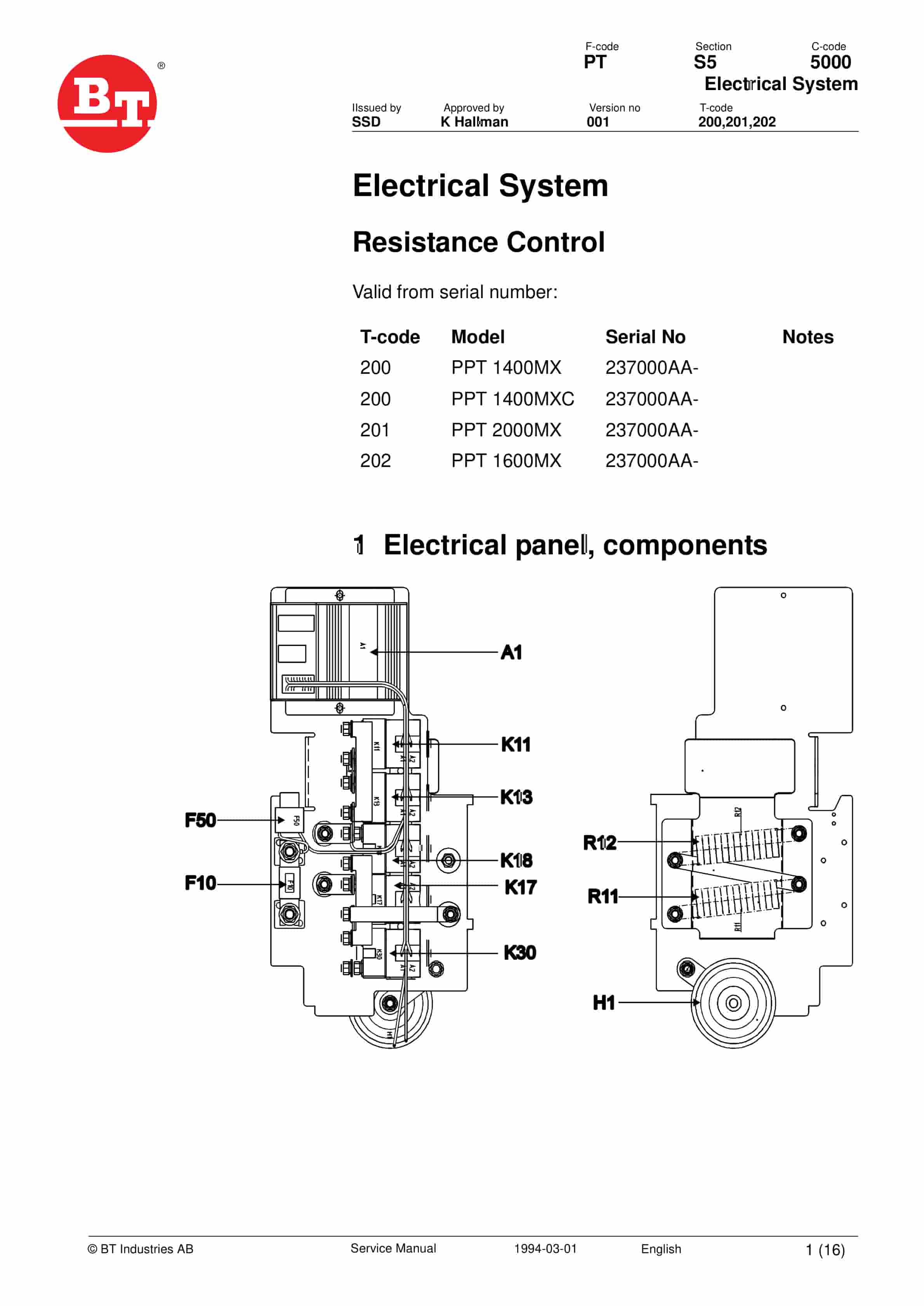
- 24.2. Electrical panel, components
- 24.3. List of symbols
- 24.3.1. Description
- 24.3.2. Function
- 24.3.3. Circuit diagram 1(3)
- 24.3.4. Circuit diagram 2(3)
- 24.3.5. Circuit diagram 3(3)
- 24.4. Description of function
- 24.4.1. General
- 24.4.2. Ignition lock S17 in the ON position
- 24.4.3. The operating arm in drive position, S10
- 24.4.4. Driving in the fork direction, 1st speed
- 24.4.5. Driving in the fork direction, 2nd speed
- 24.4.6. Driving in the fork direction, 3rd speed
- 24.4.7. Driving in the steering wheel direction, 1st speed
- 24.4.8. Driving in the steering wheel direction, 2nd speed
- 24.4.9. Driving in the steering wheel direction, 3rd speed
- 24.4.10. Reversing/ motor brake fork direction to steering wheel direction
- 24.4.11. Reversing/ motor brake steering wheel direction to fork direction
- 24.4.12. Safety reversing
- 24.4.13. Lifting of the forks
- 24.4.14. Driving in fork direction in 3rd speed and simultaneously lifting the forks
- 24.4.15. Driving in steering wheel direction in 3rd speed and simultaneously lifting the forks
- 24.4.16. Lowering the forks
- 24.4.17. Horn
- 24.4.18. Fault indication
- 25. Electrical System
- 25.1. Valid from serial number
- 25.1.1. Serial No
- 25.2. Electrical panel, components
- 25.2.1. List of symbols
- 25.2.2. Electrical diagram 1(3)
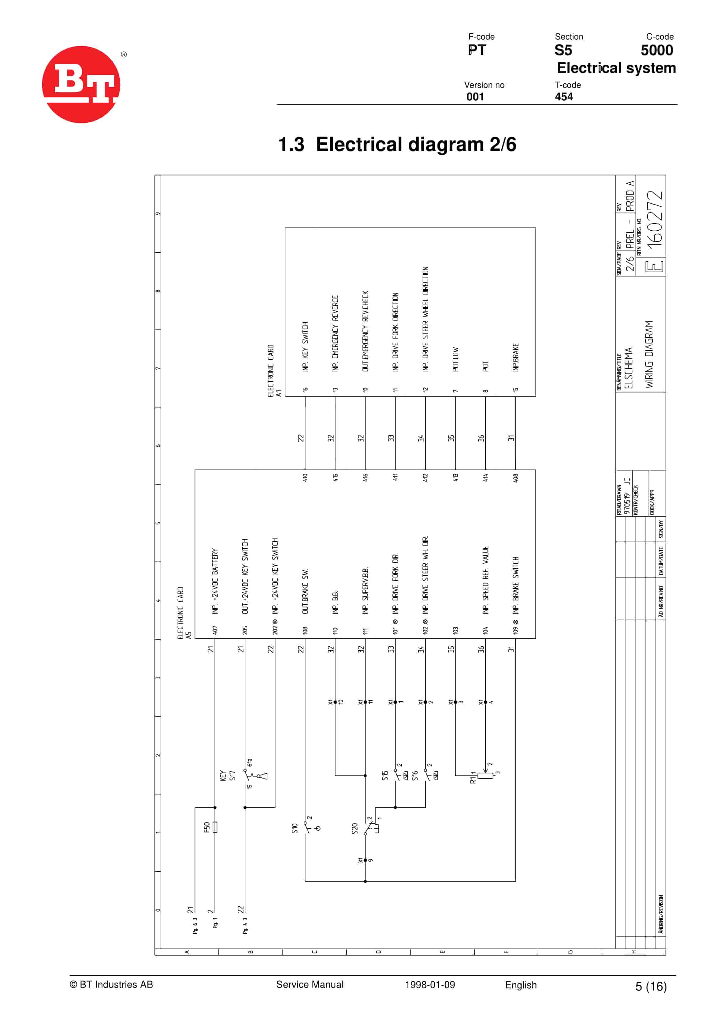
- 25.2.3. Electrical diagram 2(3)
- 25.2.4. Electrical diagram 3(3)
- 25.3. Description of function
- 25.3.1. General
- 25.3.2. Adjustable settings
- 25.3.3. Ignition lock S17 in the ON position
- 25.3.4. The operating arm in drive position, S10
- 25.3.5. Driving, fork direction
- 25.3.6. Driving, steer wheel direction
- 25.3.7. Reversing/motor brake fork direction to steer wheel direction
- 25.3.8. Reversing/motor brake steer wheel direction to fork direction
- 25.3.9. Switch for safety reversing
- 25.3.10. Lifting the forks
- 25.3.11. Driving and simultaneously lifting the forks
- 25.3.12. Lowering the forks
- 25.3.13. Horn
- 25.4. Electrical system
- 25.4.1. Valid from serial number
- 25.4.2. Electrical panel, components
- 25.4.3. Operating description
- 26. Battery controller/hourmeter
- 26.1. Valid from serial number
- 26.1.1. Serial No
- 26.2. General
- 26.3. Electrical
- 26.3.1. Voltage
- 26.4. Battery Controller
- 26.4.1. General
- 26.4.2. Reset
- 26.4.3. Keyswitch
- 26.4.4. Hourmeter
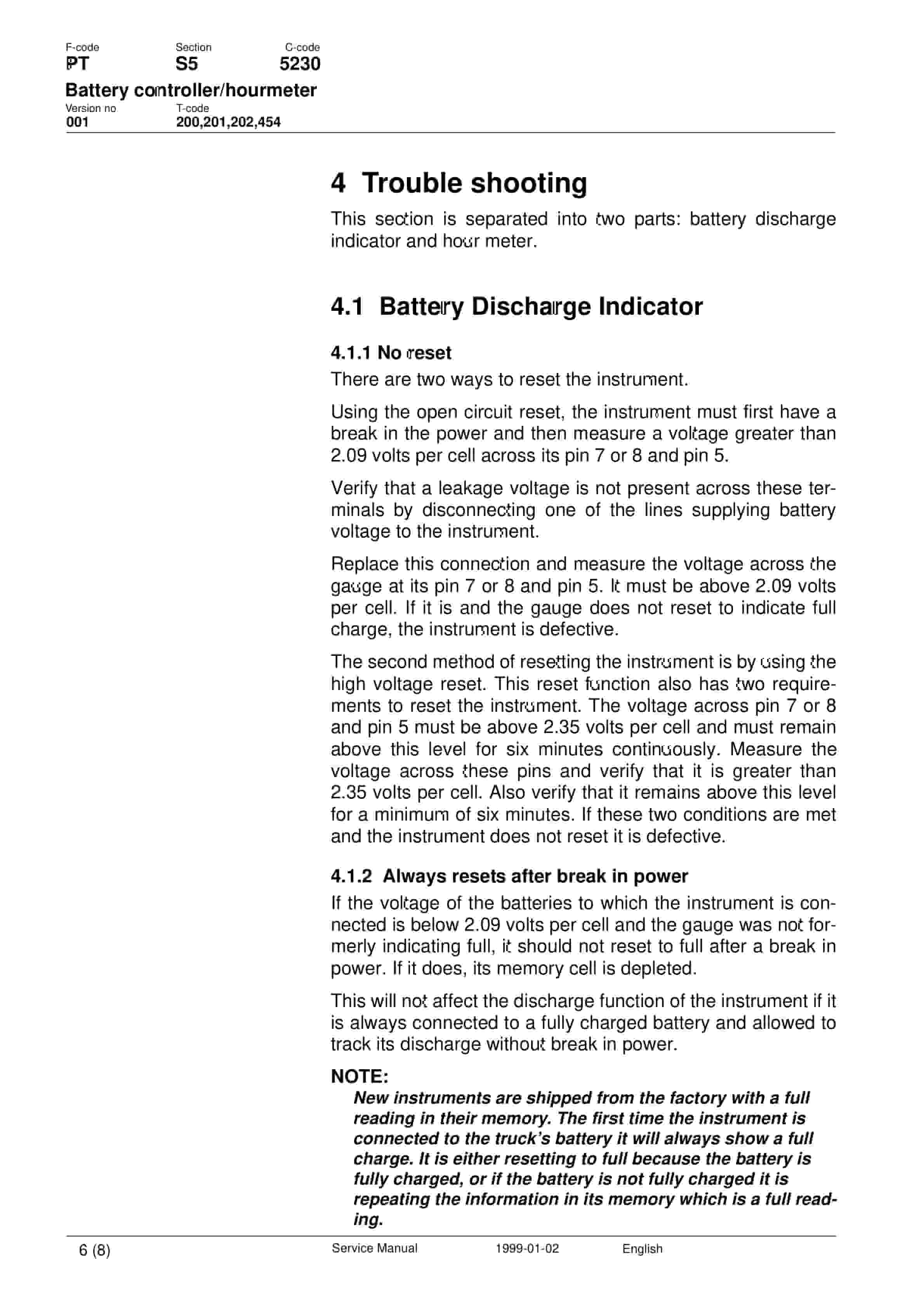
- 26.5. Trouble shooting
- 26.5.1. Battery Discharge Indicator
- 26.5.2. Hour meter
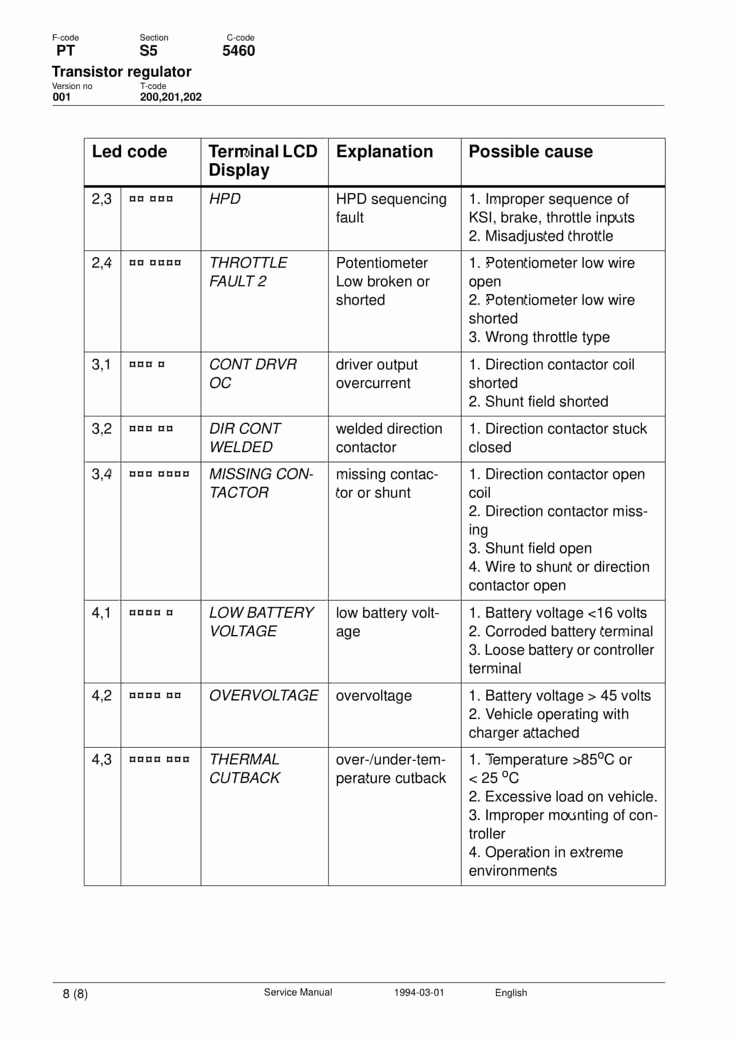
- 27. Transistor regulator
- 27.1. Valid from serial number
- 27.1.1. Serial No
- 27.2. Transistor controller, Curtis 1207
- 27.3. Motor circuit
- 27.3.1. Terminal
- 27.3.2. Connecting
- 27.4. Control circuit
- 27.4.1. Connecting
- 27.5. Technical specification
- 27.5.1. Parameter
- 27.5.2. STD setting
- 27.5.3. Description
- 27.6. Adjustment panel
- 27.6.1. Adjustable potentiometers
- 27.6.2. Connection of handheld terminal
- 27.6.3. Status LED
- 27.7. Maintenance
- 27.7.1. Safety
- 27.7.2. Cleaning
- 27.8. Diagnostics and troubleshooting
- 27.8.1. Led code
- 27.8.2. Terminal LCD Display
- 27.8.3. Explanation
- 27.8.4. Possible cause
- 28. Transistor regulator
- 28.1. Valid for serial number
- 28.2. Machine No.
- 28.3. General
- 28.3.1. Connections
- 28.4. Control circuits
- 28.4.1. Pin No.
- 28.4.2. Connection
- 28.5. Technical specification
- 28.5.1. Parameter (Terminal display)
- 28.5.2. STD value
- 28.5.3. Description
- 28.6. Adjustment panel
- 28.6.1. Adjustable potentiometers
- 28.6.2. Connection for the hand terminal
- 28.6.3. Status LED
- 28.7. Maintenance
- 28.7.1. Safety
- 28.7.2. Cleaning
- 28.8. Diagnosis and trouble shooting
- 28.8.1. LED code
- 28.8.2. Hand terminal LCD Display
- 28.8.3. Explanation
- 28.8.4. Possible cause
- 28.9. Curtis 1307 hand terminal
- 28.9.1. Function
- 28.10. Using the hand terminal
- 28.10.1. Test and adjust the parameters
- 28.10.2. Using the TEST mode
- 28.10.3. Use of diagnostic mode
- 29. Transistor regulator
- 29.1. Valid from serial number
- 29.2. Serial No.
- 29.3. General
- 29.3.1. Characteristics and functions
- 29.4. Connections
- 29.4.1. Connector
- 29.4.2. Connection
- 29.4.3. Control circuit connections
- 29.5. Technical specification
- 29.5.1. Parameter
- 29.5.2. Description
- 29.6. Parameters
- 29.6.1. Parameter (1307 display)
- 29.6.2. Std. value
- 29.6.3. Description
- 29.7. Diagnostics and trouble shooting
- 29.7.1. Trouble shooting
- 29.7.2. Error codes
- 29.7.3. Testing the error detection circuits
- 29.8. Maintenance
Related products
-
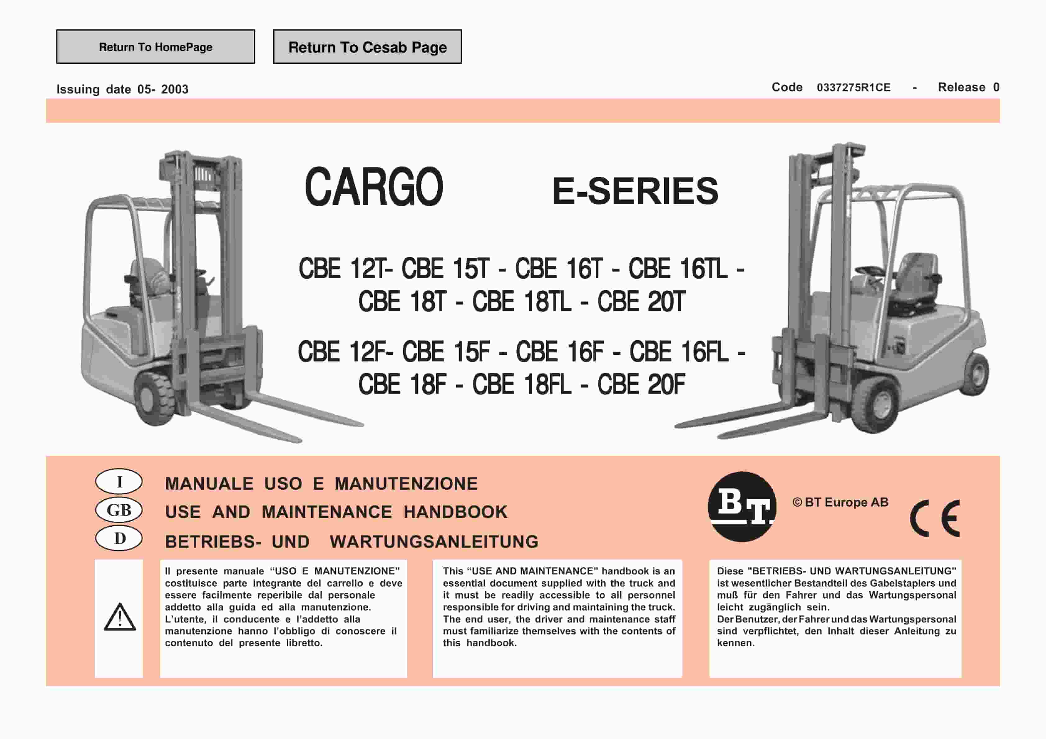
BT CARGE E-Series CBE 12T-20T, CBE 12F-20F Use And Maintenance Handbook 0337275R1CE
$30.00 Add to cart -
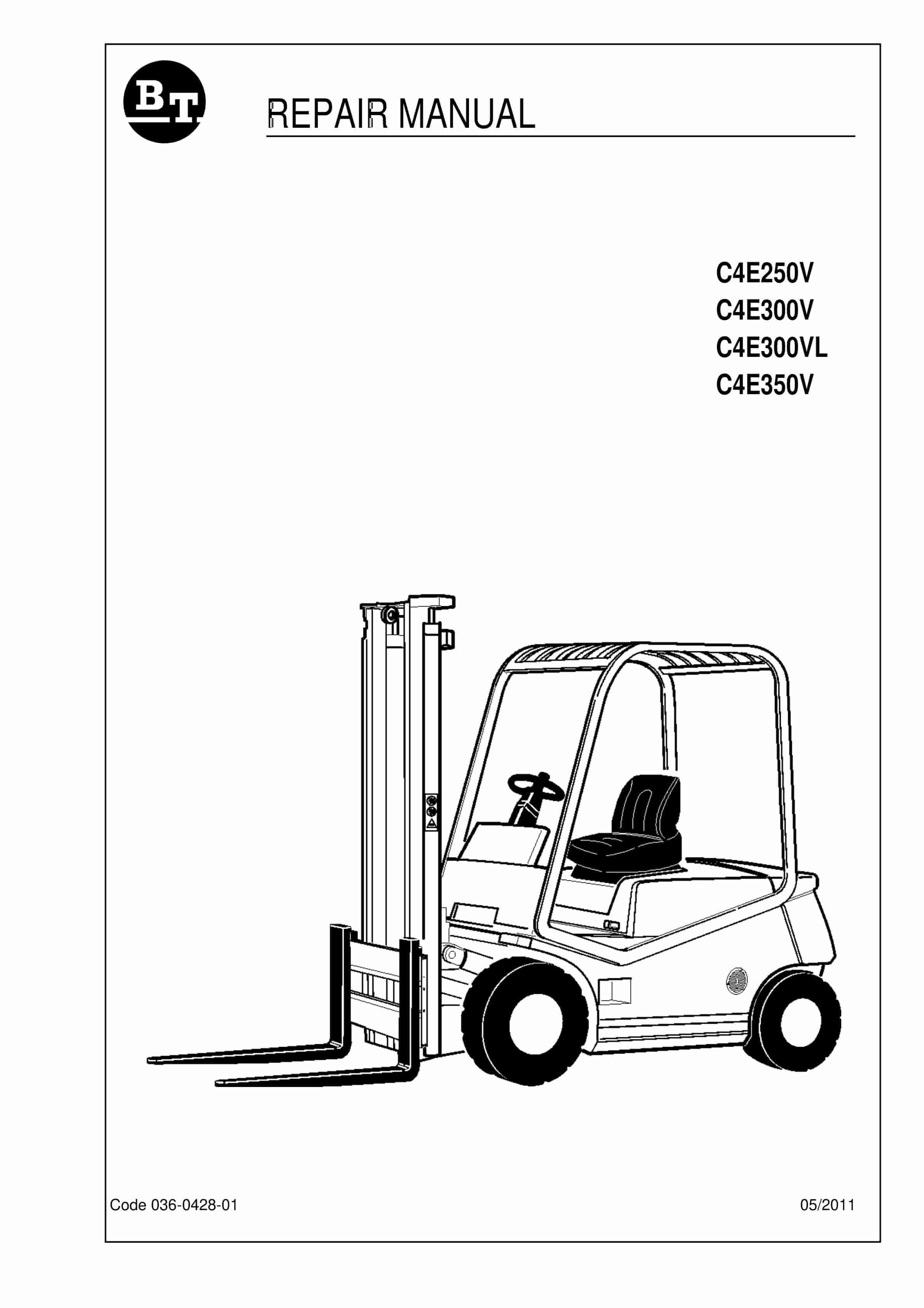
BT C4E250V, C4E300V, C4E300VL, C4E350V Repair Manual 036-0428-01
$30.00 Add to cart -
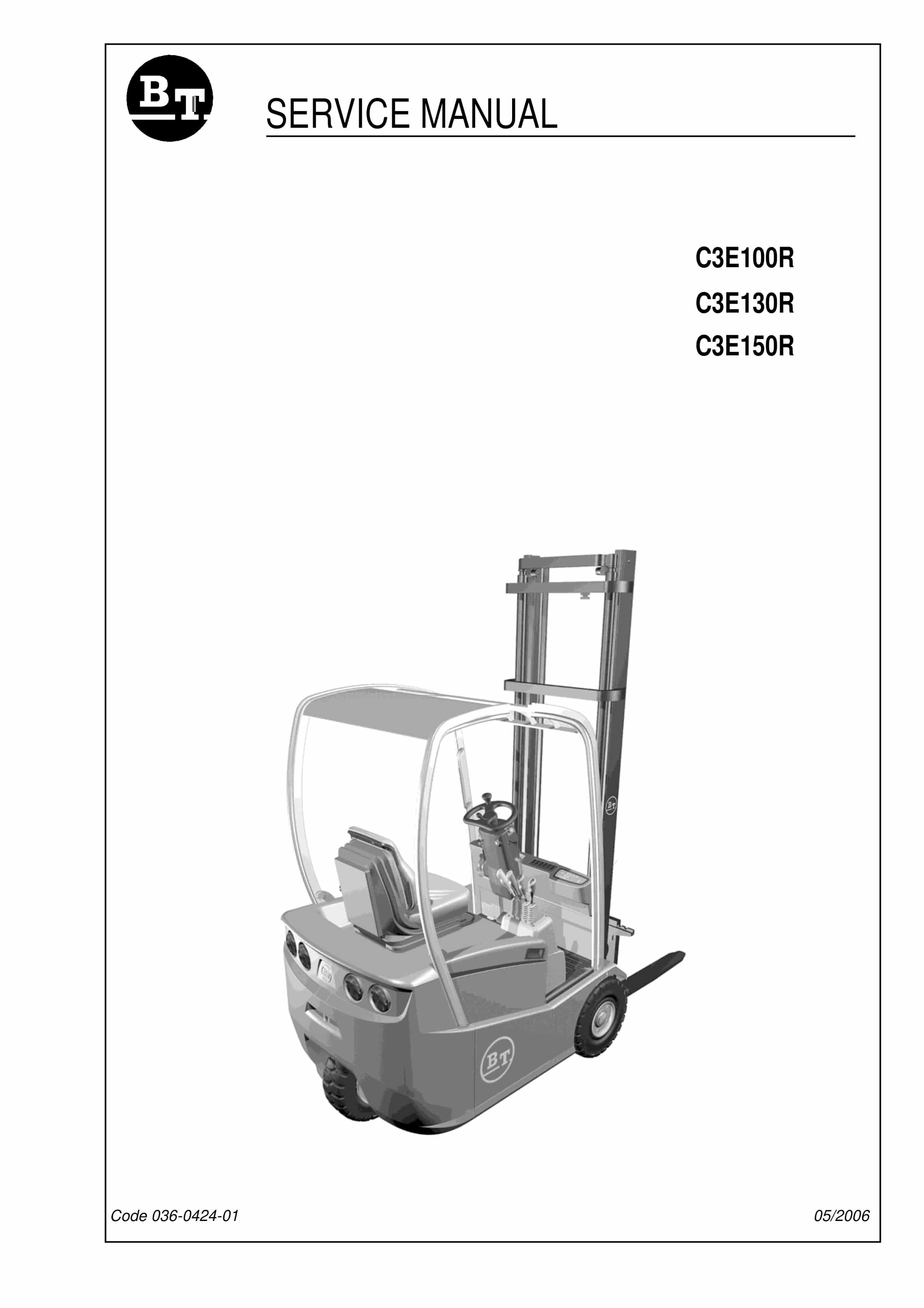
BT C3E130R, C3E150R, C3E100R Service Manual 036-0424-01
$30.00 Add to cart -
BT CBE 25, CBE 30, CBE 30L, CBE 35 Service Manual 036-0402-02
$30.00 Add to cart -
BT CBE 12T to CBE 20F Service Manual 036-0410-03
$30.00 Add to cart


