


BT LT 2200-6, LT 2200-8 Service Manual 173666-040
$30.00
- Type Of Manual: Service Manual
- Manual ID: 173666-040
- : Service Manual PDF
- Number of Pages: 190
- Size: 11.6MB
- Format: PDF
Product details
-
Model List:
- LT 2200-6, LT 2200-8
- 1. Introduction to BTs Service Manual
- 2. Contents Master Service Manual (MSM)
- 2.1. Valid from serial number
- 2.2. Serial No
- 2.3. Document list
- 2.3.1. Section
- 2.3.2. Document
- 3. Contents, M
- 3.1. Truck information
- 4. Operators manual
- 4.1. Valid from serial number
- 4.2. Serial No
- 4.3. General
- 4.3.1. Issued operators manuals
- 5. General product information
- 5.1. Valid from serial number
- 5.1.1. Serial No
- 5.2. Presentation of the truck
- 5.2.1. CAUTION
- 5.2.2. Intended application of the truck
- 5.2.3. Forbidden application of the truck
- 5.3. Truck data
- 5.3.1. Truck type
- 5.3.2. LT 2200
- 5.3.3. LT 2200-8
- 5.4. Truck dimensions
- 5.4.1. LT 2200-8
- 5.4.2. LT 2200
- 5.4.3. Measurement in mm
- 5.4.4. Measurement in mm
- 5.5. Identification plate CE
- 5.6. Identification plate CE ASME
- 5.7. Identification plate ASME
- 5.8. Modification plate
- 5.9. Main components
- 5.9.1. Tiller arm The truck can be controlled by the operator standing on the rideon platform or wa…
- 5.9.2. Identification plate With model designation, serial number, year of manufacture, weight witho…
- 5.9.3. Protective gates A higher speed of 9,5 km/h is possible with the gates folded out, while the …
- 5.9.4. Covers Easily opened and removable which allows good access when servicing.
- 5.9.5. Drive unit with brake Suspended drive unit with two stage electromagnetic brake, drive motor,…
- 5.9.6. Hydraulic unit Pump motor, pump, valves and oil tank integrated in a compact unit.
- 5.9.7. Platform Folding rideon platform which automatically folds up when not loaded.
- 5.9.8. Platform switch Switch for control of the speed range and brake function.
- 5.9.9. Support castor wheels Two support castor wheels to ensure stability. Fitted with rubber guard…
- 5.9.10. Electric panel Can be swung, which provides good access when servicing. 24 volt electrical s…
- 5.9.11. Lift cylinders Located along the sides of the truck.
- 5.9.12. Fork carriage The forks are held horizontal by a link system. The fork carriage requires no …
- 5.9.13. Serial number Serial number plate fitted to the chassis. Partly hidden by the emergency disc…
- 5.9.14. Emergency disconnector and battery connector The battery is charged via the permanently fitt…
- 5.9.15. Battery 24 V with different Ah values. Stands on rollers to facilitate replacement.
- 5.10. Warning and information plates and symbols
- 5.10.1. Signal/Horn
- 5.10.2. Hydraulic control Lower
- 5.10.3. Hydraulic control Lift
- 5.10.4. Travel direction
- 5.10.5. Hydraulic oil filling
- 5.10.6. Lifting points
- 5.10.7. Serial number
- 5.10.8. Identification plate
- 5.10.9. Modification plate
- 6. Technical data
- 6.1. Valid from serial number
- 6.1.1. Serial No
- 6.2. LT 2200
- 6.2.1. Drive motor
- 6.2.2. Transmission/drive gear
- 6.2.3. Hydraulic system
- 6.2.4. Batteries
- 6.2.5. Driving speed
- 6.2.6. Lifting-/lowering speed
- 6.2.7. Power consumption
- 7. Ordering Spare Parts
- 8. Quality Parts
- 8.1. Valid from serial number
- 8.2. Serial No
- 8.3. Issued Quality Parts
- 8.3.1. Serial No
- 8.3.2. Order number
- 9. Recommended Spare Parts (RSP)
- 9.1. Valid from serial number
- 9.2. Serial No
- 9.3. Issued RSP
- 9.3.1. Version
- 9.3.2. Serial No
- 10. Contents, P
- 10.1. Preventive Maintenance
- 11. Introduction, maintenance
- 11.1. Safety regulations with maintenance work
- 11.1.1. WARNING
- 11.1.2. WARNING
- 11.1.3. WARNING
- 11.1.4. CAUTION
- 11.2. Cleaning and washing
- 11.2.1. External cleaning
- 11.2.2. Cleaning the motor compartment
- 11.2.3. Electrical components
- 11.3. Safe lifting
- 11.3.1. WARNING
- 12. Preventive maintenance
- 12.1. Valid from serial number
- 12.1.1. Serial No
- 12.2. Service schedule
- 12.2.1. Pos. nr.
- 12.2.2. Work to carry out
- 12.3. Lubrication chart
- 12.3.1. Service point
- 12.3.2. Interval/Running hours
- 12.3.3. Lubricant
- 13. Oil and grease specification
- 13.1. Valid from serial number
- 13.1.1. Serial No
- 13.2. Lubricant
- 13.3. Specification
- 13.4. Application area
- 13.4.1. > – 15C
- 13.4.2. < – 15C
- 14. Contents, S
- 14.1. Service instructions
- 15. Electric drive motor
- 15.1. Valid from serial number
- 15.2. Serial number
- 15.3. General
- 15.3.1. Mechanical construction
- 15.3.2. Special tools
- 15.4. Removal/Refitting
- 15.4.1. Removing the motor from the truck
- 15.4.2. Re-assembly
- 15.5. Service/Repairs
- 15.5.1. Cleaning
- 15.5.2. Removal of motor
- 15.5.3. Refitting of motor
- 15.5.4. Armature bearings
- 15.5.5. Carbon brushes and brush holder
- 15.5.6. Commutator
- 15.6. Storage/Transport
- 15.6.1. Storage
- 15.6.2. Grease specification
- 15.6.3. Component
- 16. Mechanical drive gear unit
- 16.1. Valid from serial number
- 16.1.1. Serial No
- 16.2. General technical description
- 16.2.1. Technical data
- 16.2.2. Gear components
- 16.2.3. Special tools
- 16.3. Removing the gear from the truck
- 16.4. Change of seal on the drive shaft
- 16.5. Reconditioning of the gear
- 17. Electromagnetic parkingbrake
- 17.1. Valid from serial number
- 17.1.1. Serial No
- 17.2. General
- 17.3. Function
- 17.3.1. Releasing the brake
- 17.3.2. Braking
- 17.4. Maintenance
- 17.4.1. Adjustment of gap
- 17.4.2. Exchange of brake disc/magnetic coil
- 17.4.3. Check/adjustment of the braking force
- 18. Electrical system
- 18.1. Valid from serial numbers
- 18.2. Serial number
- 18.3. Electrical panel
- 18.4. List of symbols
- 18.4.1. Description
- 18.4.2. Function
- 18.4.3. List of symbols for logic card
- 18.5. Electrical diagram
- 18.5.1. Electrical diagram, standard 1/3
- 18.5.2. Electrical diagram, EU gates 2/3
- 18.5.3. Electrical diagram, safety gates 3/3
- 18.6. Operating description
- 18.6.1. General
- 18.6.2. Description
- 19. Electrical system
- 19.1. Valid from serial number
- 19.2. Serial number
- 19.3. Electrical panel
- 19.4. List of symbols
- 19.4.1. Description
- 19.4.2. Function
- 19.4.3. Electrical diagram 1/5
- 19.4.4. Electrical diagram 2/5
- 19.4.5. Electrical diagram 3/5
- 19.4.6. Electrical diagram 4/5
- 19.4.7. Electrical diagram 5/5
- 19.5. Description of function
- 19.5.1. General
- 19.6. Description
- 19.6.1. Ignition switch S17 in the ON position
- 19.6.2. Tiller arm in driving position, S10 in the On position
- 19.6.3. Driving in the fork direction
- 19.6.4. Driving in the steer wheel direction
- 19.6.5. Load dependent current limit
- 19.6.6. S59 Activation range
- 19.6.7. Reverse/motor brake, fork direction to steer wheel direction
- 19.6.8. Reverse/motor brake, steer wheel direction to fork direction
- 19.6.9. Safety reversing function
- 19.6.10. Lifting the forks
- 19.6.11. Lowering the forks
- 19.6.12. Horn
- 19.6.13. Switch operation for the platform and gates
- 20. Electrical system
- 20.1. Valid from serial number
- 20.2. Serial number
- 20.3. Electrical panel
- 20.4. List of symbols
- 20.4.1. Description
- 20.4.2. Function
- 20.4.3. List of symbols for the logic card A1
- 20.5. Electrical diagrams
- 20.5.1. Electrical diagram, standard
- 20.5.2. Electrical diagram, EEC-gates
- 20.5.3. Electrical diagram, safety gates
- 20.6. Description of function
- 20.6.1. General
- 20.6.2. Ignition switch, S17 ON
- 20.6.3. Driving
- 20.6.4. Driving forwards, direction of the forks, first speed stage
- 20.6.5. Reversing, direction of the drive wheel, first speed stage
- 20.6.6. Driving forwards or reversing, second speed stage
- 20.6.7. Driving forwards or reversing, third speed range
- 20.6.8. Reversing/ motor brake
- 20.6.9. Safety reversing
- 20.6.10. Lifting the forks
- 20.6.11. Lowering the forks
- 21. Electrical system
- 21.1. Valid from serial number
- 21.2. Serial number
- 21.3. Electrical panel
- 21.4. List of symbols
- 21.4.1. Description
- 21.4.2. Function
- 21.4.3. Electrical diagram 1/5
- 21.4.4. Electrical diagram 2/5
- 21.4.5. Electrical diagram 3/5
- 21.4.6. Electrical diagram 4/5
- 21.4.7. Electrical diagram 5/5
- 21.5. Description of function
- 21.5.1. General
- 21.5.2. Description
- 21.5.3. Ignition switch S17 in ON position
- 21.5.4. Tiller arm in driving position, S10
- 21.5.5. Driving, direction of the forks
- 21.5.6. Driving, steer wheel direction
- 21.5.7. Switch function for platform (option)
- 21.5.8. Load dependent current limit
- 21.5.9. S59 Activation range
- 21.5.10. Reversing/motor brake, fork direction to steer wheel direction
- 21.5.11. Reversing/motor brake, steer wheel direction to fork direction
- 21.5.12. Safety reversing function
- 21.5.13. Lifting the forks
- 21.5.14. Lowering the forks
- 21.5.15. Horn
- 22. Volt-/battery indicator
- 22.1. Valid from serial number
- 22.1.1. Serial No
- 22.2. General
- 22.3. Electrical
- 22.3.1. Voltage
- 22.4. Battery Controller
- 22.4.1. General
- 22.4.2. Reset
- 22.4.3. Keyswitch
- 22.4.4. Hourmeter
- 22.5. Trouble shooting
- 22.5.1. Battery Discharge Indicator
- 22.5.2. Hour meter
- 23. Transistor panel
- 23.1. Valid from serial number
- 23.2. Serial number
- 23.3. General
- 23.3.1. Construction
- 23.3.2. Operation
- 23.4. Technical specification
- 23.4.1. Characteristics
- 23.5. Settings and indications
- 23.5.1. Connection pin 23
- 23.5.2. Rotor current
- 23.5.3. Shunt field current
- 23.5.4. S2s position
- 23.5.5. Ramp time
- 23.5.6. LED No.
- 23.5.7. Normal status
- 23.5.8. Explanation
- 23.6. Maintenance
- 23.6.1. Watchdog
- 23.6.2. Adjusting the current limit
- 23.6.3. Trouble shooting
- 23.6.4. Main transistor check
- 23.6.5. Check the transistor regulators safety circuit
- 24. Transistor panel
- 24.1. Valid from serial number
- 24.2. Serial number
- 24.3. General
- 24.3.1. Characteristics and functions
- 24.4. Connections
- 24.4.1. Connection pin
- 24.4.2. Connection
- 24.4.3. Connection to the control circuits
- 24.5. Technical specification
- 24.5.1. Description
- 24.6. Parameters
- 24.6.1. Parameter (1307-display)
- 24.6.2. Std. value
- 24.6.3. Description
- 24.6.4. Mode 1 and 2
- 24.7. Diagnostics and trouble shooting
- 24.7.1. Trouble shooting
- 24.7.2. Error codes
- 24.7.3. Testing circuits for error detection
- 24.8. Maintenance
- 24.8.1. Safety
- 24.8.2. Cleaning
- 24.9. Curtis 1307 hand terminal
- 24.9.1. Function
- 24.10. Using the hand terminal
- 24.10.1. Using the PROGRAM mode, checking and adjusting parameters
- 24.10.2. Using SPECIAL PROGRAM mode
- 24.10.3. Using TEST mode
- 24.10.4. Using DIAGNOSTICS mode
- 24.10.5. Using SPECIAL DIAGNOSTICS mode
- 25. Electronic card, drive/multi function
- 25.1. Valid from serial number
- 25.2. Serial number
- 25.3. General
- 25.4. Components
- 25.4.1. Connection/adjustments
- 25.4.2. Connections for inputs and outputs
- 26. Electronic card drive/multi function
- 26.1. Valid from serial number
- 26.2. Serial number
- 26.3. General
- 26.4. Components
- 26.4.1. Connections/adjustments
- 26.4.2. Connections for inputs/outputs
- 27. Hydraulic/pneumatic system
- 27.1. Valid from serial number
- 27.2. Serial number
- 27.3. General
- 27.4. Hydraulic chart and list of symbols
- 27.4.1. List of Symbols
- 27.5. Operating description
- 27.5.1. Lifting the forks
- 27.5.2. Lowering the forks
- 27.5.3. Switch, S59
- 27.6. Adjustments
- 27.6.1. Adjusting the pressure limit valve
- 28. PTfirst2.GB.pdf
- 28.1. Master Service Manual Product family PT
- 28.1.1. LT 2200-6 LT 2200-8
- 28.1.2. C-code revision 2
Related products
-
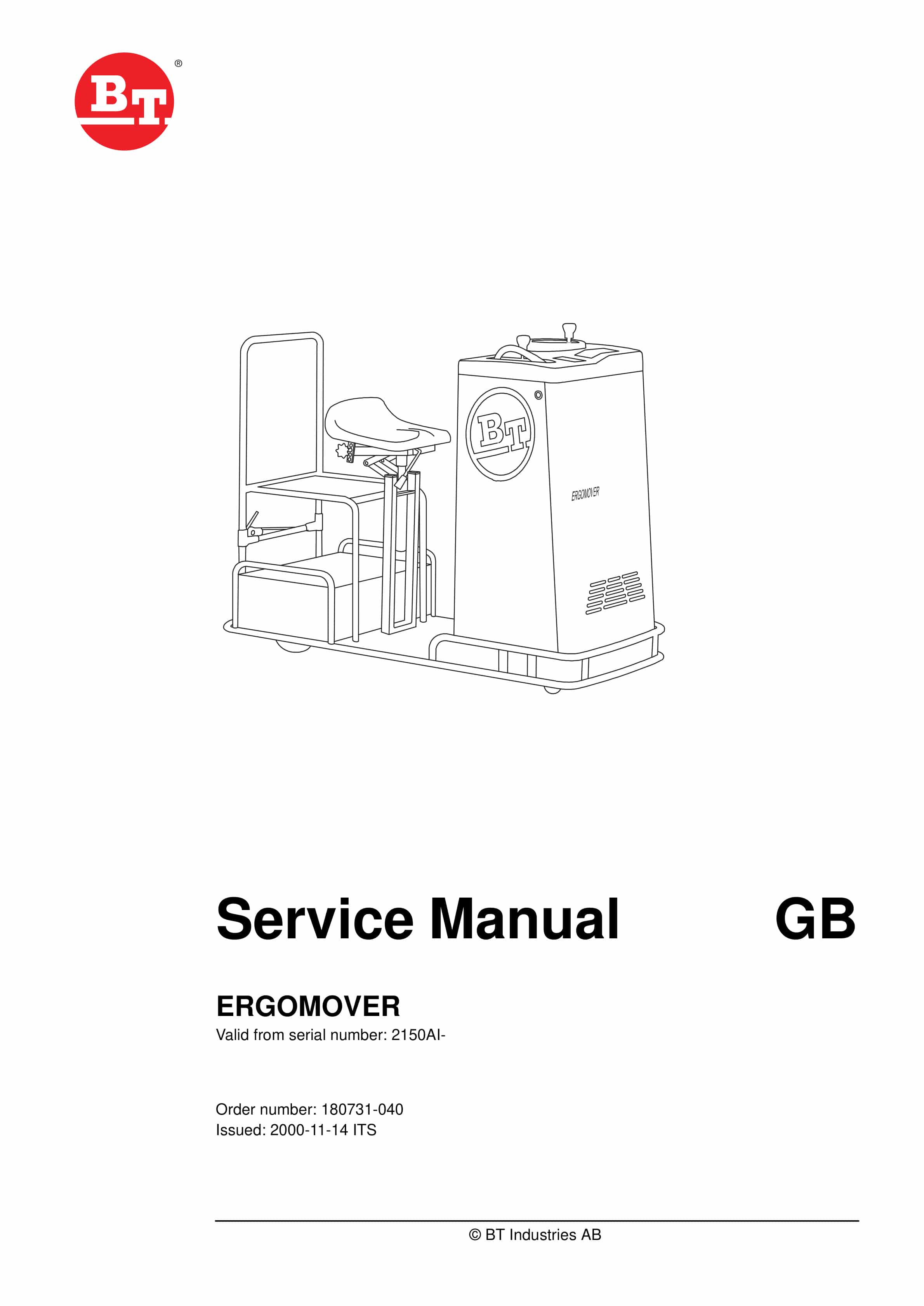
BT ERGOMOVER Service Manual 180731-040
$30.00 Add to cart -
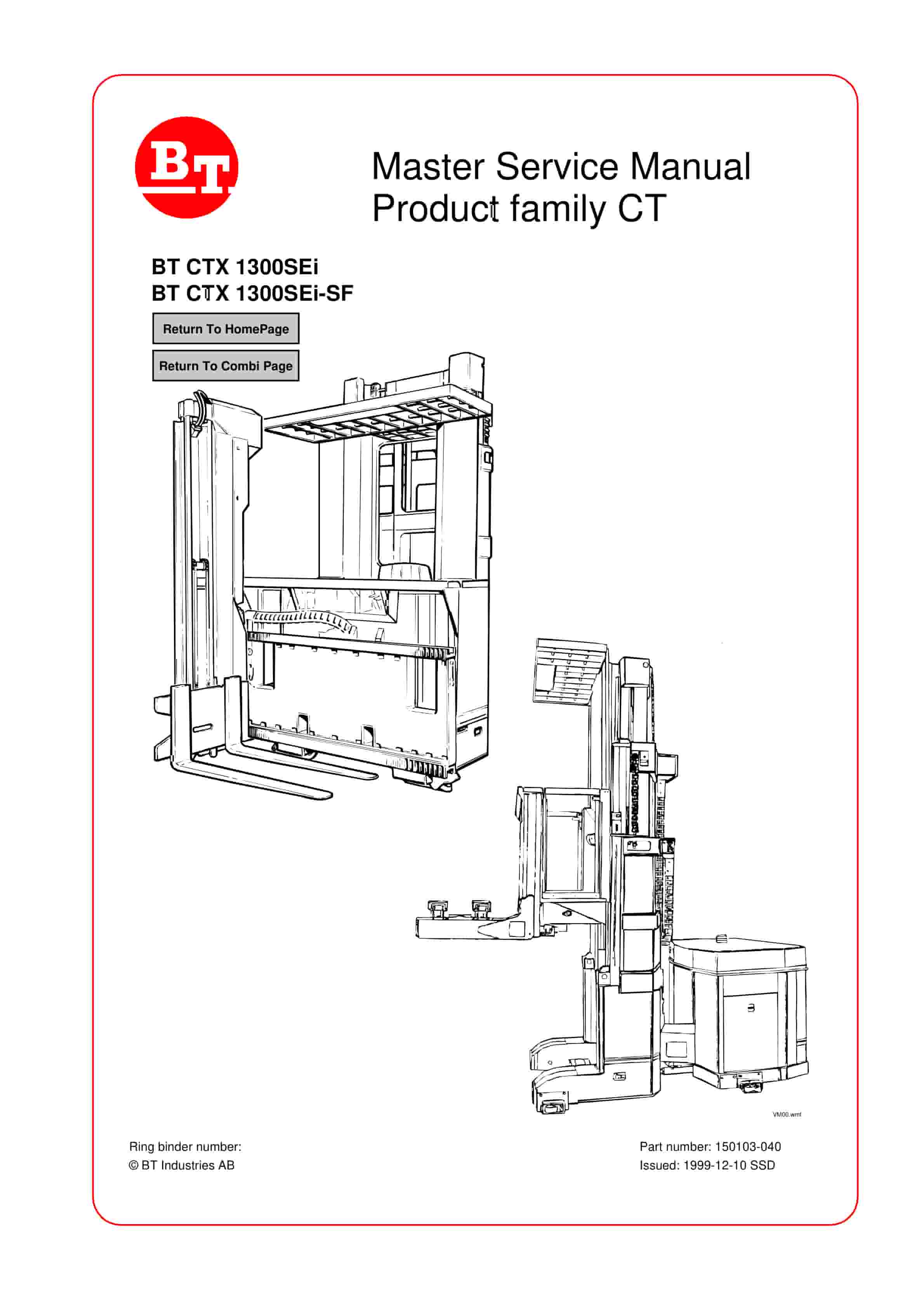
BT CTX 1300SEi, CTX 1300SEi SF Service Manual 150103-040
$30.00 Add to cart -
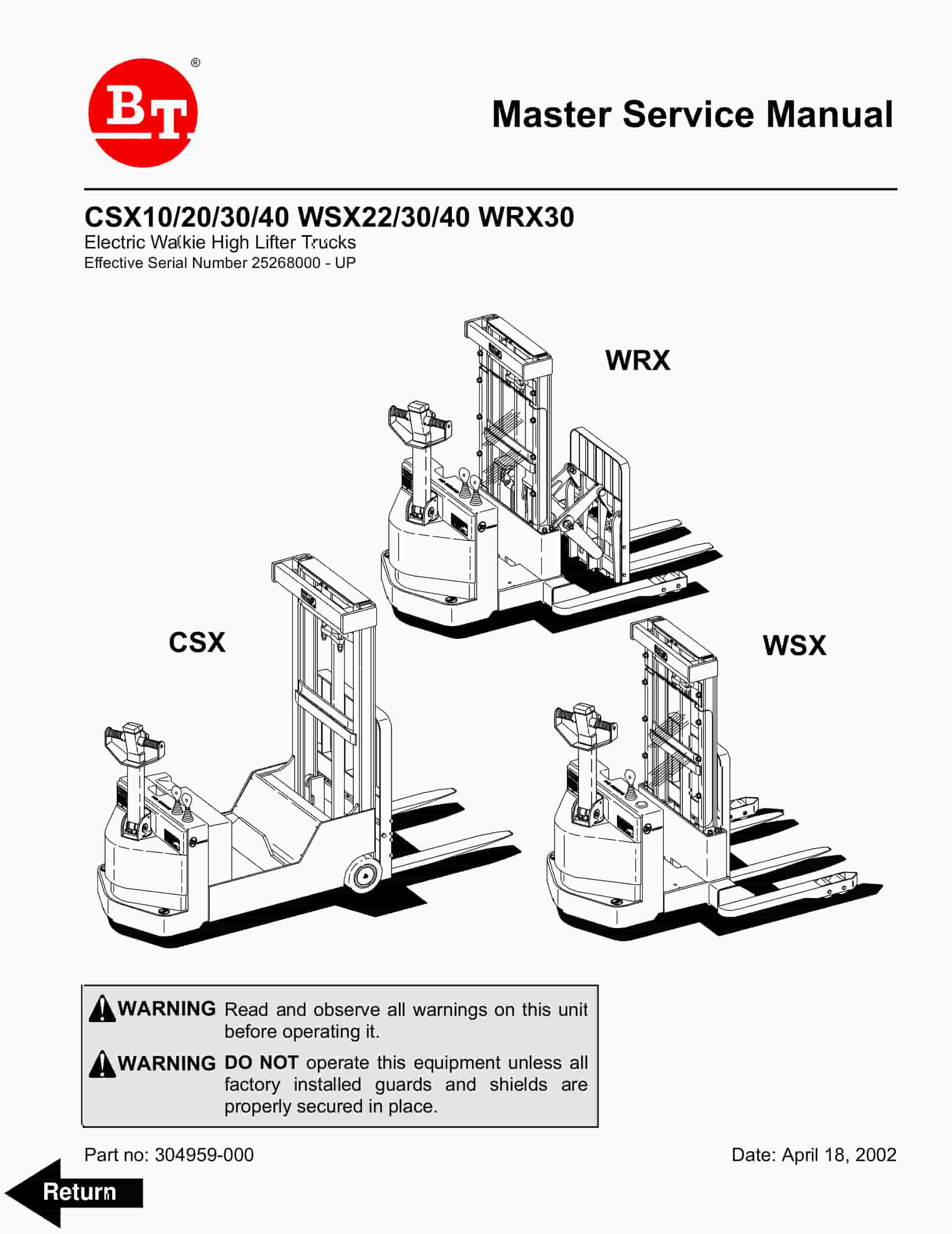
BT CSX10, CSX20, CSX30, CSX40, WSX22, WSX30, WSX40, WRX30 Electric Walkie High Lifter Truck Service Manual 304959-000
$30.00 Add to cart -
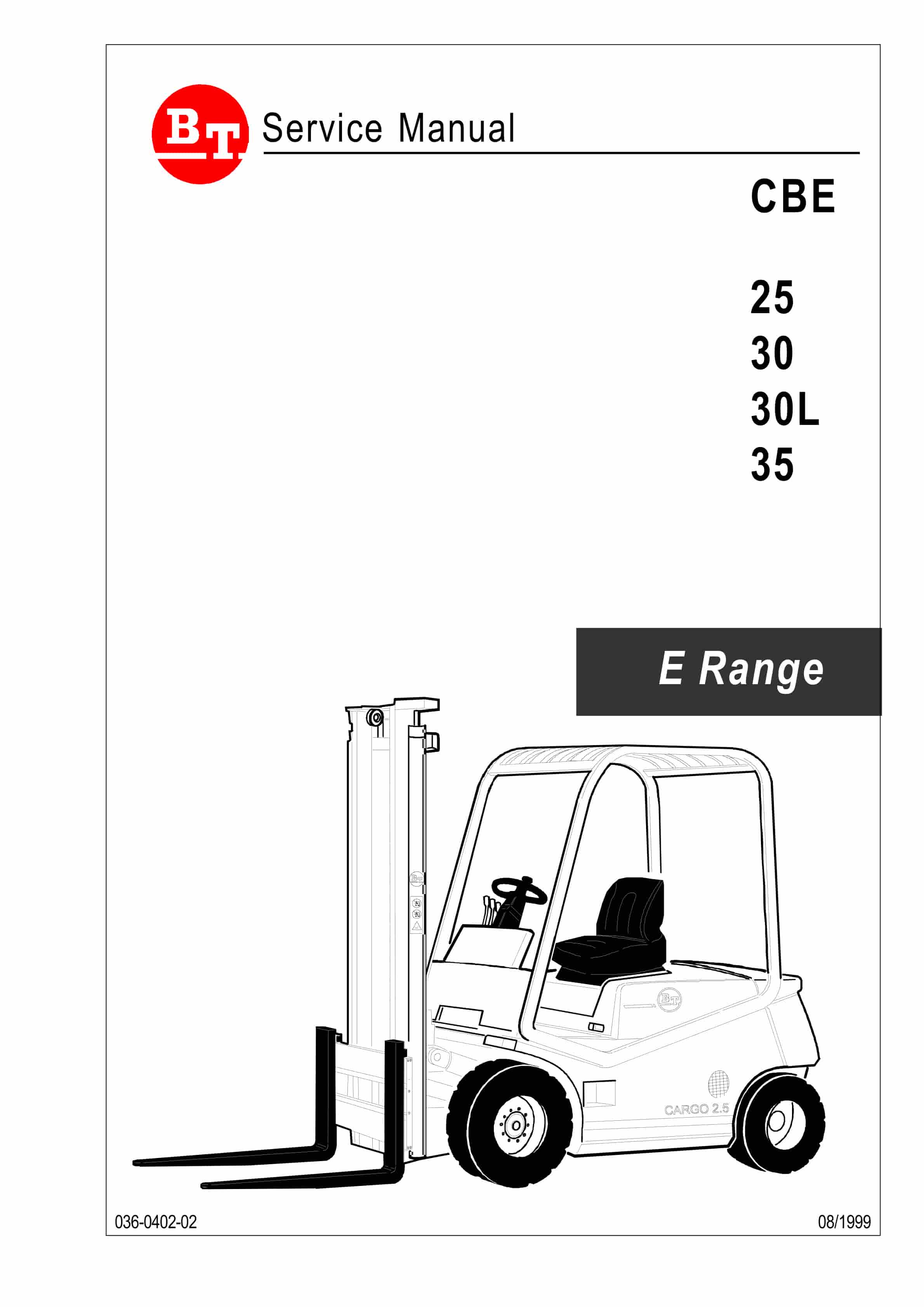
BT CBE 25, CBE 30, CBE 30L, CBE 35 Service Manual 036-0402-02
$30.00 Add to cart -
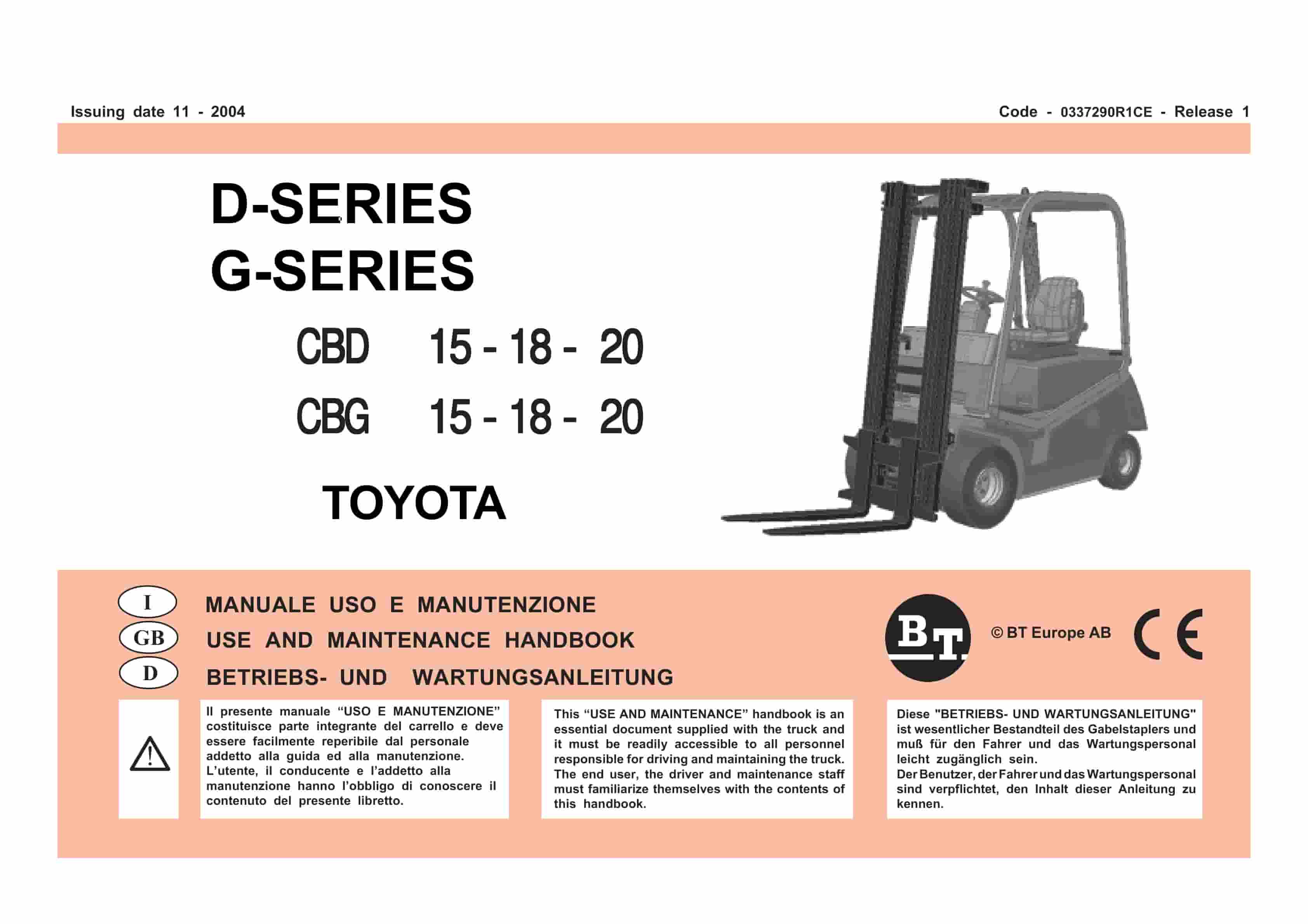
BT D-G-Series CBD15, CBD18, CBD20, CBG15, CBG18, CBG20 Use And Maintenance Handbook 0337290R1CE
$30.00 Add to cart