

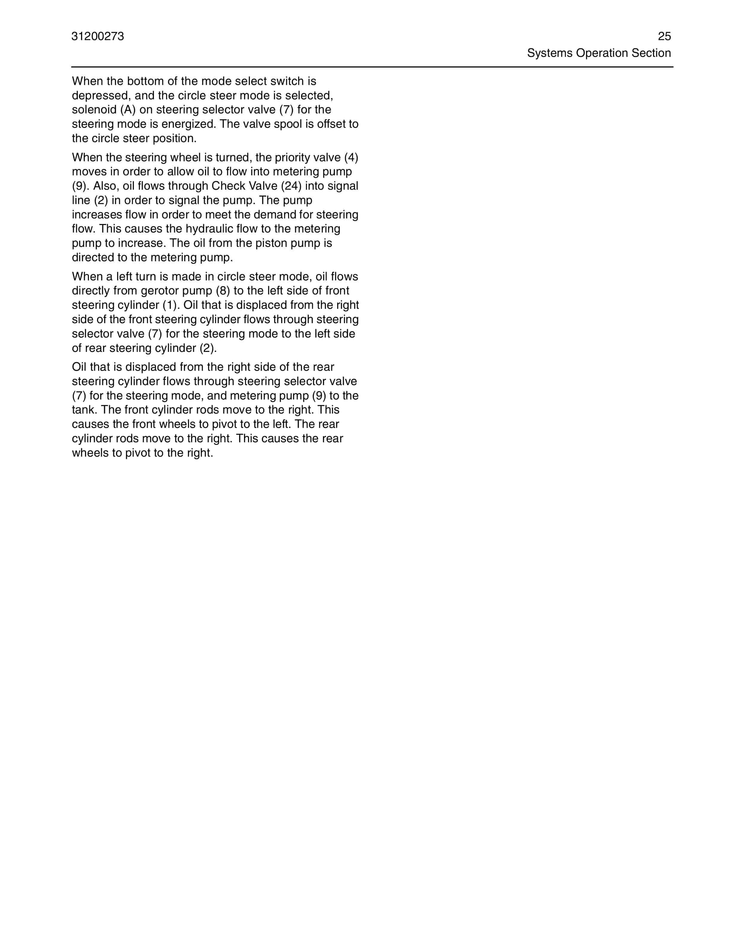
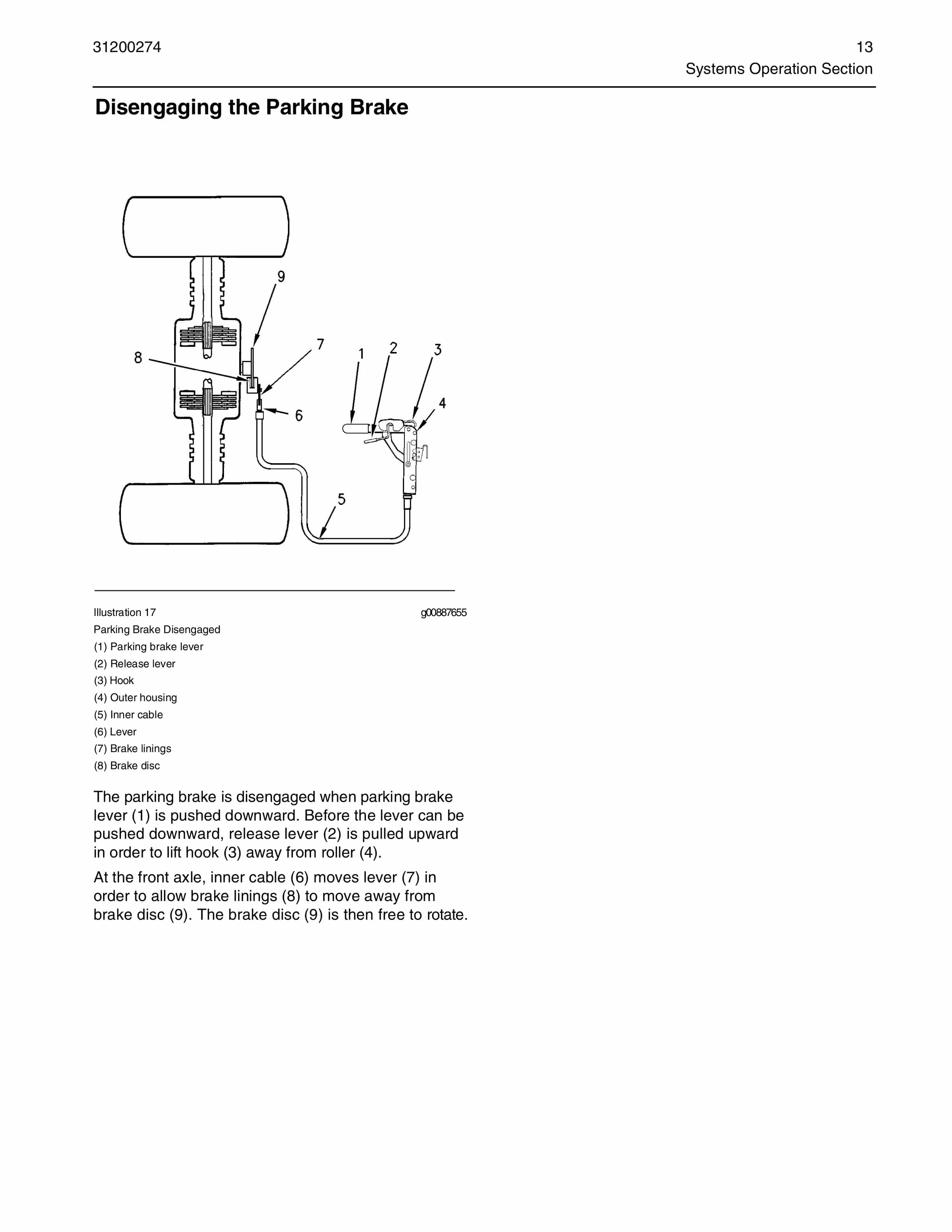

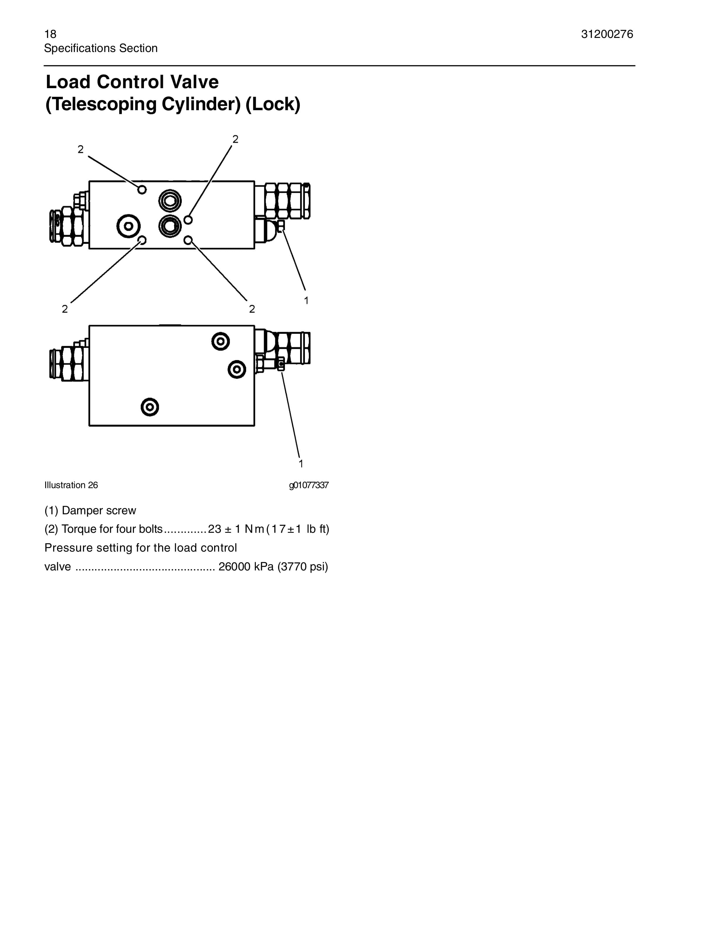
Caterpillar TH220B, TH330B Telehandler Hydraulic System Systems Operation Testing And Adjusting 31200272
$30.00
- Type Of Manual: Systems Operation Testing And Adjusting
- Manual ID: 31200272
- Number of Pages: 324
- Size: 63.4MB
- Format: PDF
Product details
-
Model List:
- TH220B, TH330B Telehandler Hydraulic System
- 1. Systems Operation Section
- 2. Graphic Color Codes …………………………. 3
- 3. Introduction………………………………………. 4
- 4. General Information…………………………… 5
- 5. Main Control Valve Group (Implement)5
- 6. Electronic Pilot Valve Group
- 7. (Implement) ………………………………….. 6
- 8. Machine ECM……………………………….. 7
- 9. Electronic Joystick…………………………. 8
- 10. Operator Switches…………………………. 9
- 11. Piston Pump (Implement and Steering)9
- 12. Hydraulic Oil Tank…………………………. 9
- 13. Hydraulic Oil Filter…………………………. 9
- 14. System Operation………………………… 10
- 15. Load Independent Flow Division
- 16. (LIFD) ………………………………………… 11
- 17. Location of Electrical Components…. 11
- 18. Switch (Lockout Control) ………………. 11
- 19. Joystick Control…………………………… 11
- 20. Sensor (Boom Raise/Lower) …………. 12
- 21. Sensor For Boom Extend And Boom
- 22. Retract Or Boom Tilt Forward And
- 23. Rackback……………………………………. 12
- 24. Switch (Continuous Auxiliary Flow)… 12
- 25. Switch For Boom Extend and Boom
- 26. Retract Or Boom Tilt Forward And
- 27. Rackback……………………………………. 12
- 28. Switch (Auxiliary Actuator in the +
- 29. Direction)……………………………………. 12
- 30. Switch (Auxiliary Actuator in the –
- 31. Direction)……………………………………. 12
- 32. Switch (Auxiliary Services 1 or 2)…… 12
- 33. Switch (Quick Coupler)…………………. 13
- 34. Switch (Frame Level) …………………… 13
- 35. Switch (Fully Lowered Boom)………… 13
- 36. Switch (Critical Angle) ………………….. 14
- 37. Switch (Fully Retracted Boom)………. 14
- 38. Switch (Reversing Fan (If Equipped)) 14
- 39. Machine (ECM) …………………………… 14
- 40. Main Control Valve (Implement)…….. 15
- 41. Solenoids (Frame Level) ………………. 15
- 42. Solenoid (Diverter Valve) ……………… 15
- 43. Relay (Frame Level)…………………….. 16
- 44. Relays (Diverter Valve) ………………… 16
- 45. Relays (Quick Coupler) ………………… 16
- 46. Location of Hydraulic Components…….. 17
- 47. Hydraulic Tank ……………………………. 17
- 48. Piston Pump (Implement and
- 49. Steering)…………………………………….. 17
- 50. Compensator Valve ………………………18
- 51. Main Control Valve Group
- 52. (Implement)………………………………….18
- 53. Inlet Manifold ……………………………….18
- 54. Outlet Manifold……………………………..19
- 55. Trailer and Towing Hitch Hydraulic
- 56. System (Option)……………………………19
- 57. Boom Cylinder ……………………………..20
- 58. Load Control Valve (Boom Cylinder
- 59. Lock)…………………………………………..21
- 60. Telescoping Cylinder …………………….21
- 61. Load Control Valve (Telescoping
- 62. Cylinder Lock)………………………………21
- 63. Tilt Cylinder………………………………….21
- 64. Lock for Load Control Valve (Tilt
- 65. Cylinder) ……………………………………..22
- 66. Compensating Cylinder …………………22
- 67. Load Control Valve (Compensating
- 68. Cylinder Lock)………………………………22
- 69. Frame Leveling Cylinder………………..22
- 70. Lock Valve (Frame Leveling Cylinder)23
- 71. Diverter Valve ………………………………23
- 72. Quick Coupler Cylinder………………….23
- 73. Electrical Input Components ………………24
- 74. Switches ……………………………………..25
- 75. Joystick Control ……………………………25
- 76. Auxiliary Switches…………………………25
- 77. Thumb Slider ……………………………….25
- 78. Boom Critical Angle Switch…………….25
- 79. Frame Leveling Switch ………………….25
- 80. Boom Retracted Switch …………………25
- 81. Quick Coupler Switch ……………………26
- 82. Continuous Flow Switch ………………..26
- 83. Implement Lockout Switch……………..26
- 84. Boom Lowered Switch…………………..26
- 85. Electronic Control Module………………….27
- 86. Inputs………………………………………….27
- 87. Outputs ……………………………………….27
- 88. Data Links……………………………………27
- 89. Input/Output…………………………………27
- 90. Electrical Output Components ……………29
- 91. Relays…………………………………………30
- 92. Solenoids…………………………………….30
- 93. Electrical Function Requirements ……….31
- 94. Transmission Neutralizer……………….31
- 95. Solenoid Outputs ………………………….31
- 96. System Voltage…………………………….31
- 97. Shuttle Shift for the Power Shuttle
- 98. Transmission ……………………………….31
- 99. Shift Lever (Cat Data Link) for
- 100. Powersynchro Transmission…………..31
- 101. Rear Axle Lock (if equipped)…………..31
- 102. Machine Security System ………………31
- 103. Parking Brake ………………………………31
- 104. Service Brake Pressure Switch for the
- 105. Transmission Neutralizer ……………….31
- 106. More Electrical Function
- 107. Requirements……………………………….31
- 108. Steering……………………………………….32
- 109. The Neutral Start Is Disabled………….32
- 110. Stabilizer Raise/Lower (if equipped) is
- 111. Disabled ………………………………………32
- 112. Boom Raise/Lower Is Disabled……….33
- 113. The Boom Extend/Retract Is Disabled33
- 114. Disable The Rackback And Dump …..33
- 115. The Frame Level (if equipped) is
- 116. Disabled ………………………………………33
- 117. Disable the Quick Coupler ……………..34
- 118. Miscellaneous ………………………………34
- 119. Electrical Schematic………………………….35
- 120. Programmable Hydraulic System
- 121. (PHS) ………………………………………….36
- 122. Piston Pump (Implement and Steering) .37
- 123. Piston Pump…………………………………37
- 124. Compensator Valve ………………………38
- 125. Low Pressure Standby…………………..39
- 126. Upstroke………………………………………40
- 127. Constant Flow ………………………………41
- 128. Destroke………………………………………42
- 129. High Pressure Stall ……………………….44
- 130. Main Control Valve (Implement) ……..45
- 131. Manifold Valve (Inlet) …………………….47
- 132. Check and Relief Valves ……………………49
- 133. Manifold Valve (Outlet)………………………49
- 134. Pilot Hydraulic System ………………………51
- 135. Telescoping System ………………………….53
- 136. Valve for the Telescoping Cylinder in the
- 137. HOLD Position ……………………………..53
- 138. Valve for the Telescoping Cylinder in the
- 139. EXTEND Position………………………….55
- 140. Valve for the Telescoping Cylinder in the
- 141. RETRACT Position ……………………….57
- 142. Hydraulic Fan System ……………………….58
- 143. Reversing Fan (If Equipped) …………..58
- 144. Auxiliary Hydraulic System…………………60
- 145. Auxiliary Control (Combined Circuit)..61
- 146. Auxiliary Circuit 1 ………………………….63
- 147. Auxiliary Circuit 2 ………………………….64
- 148. Continuous Flow (Auxiliary
- 149. Hydraulics)………………………………….. 65
- 150. Quick Coupler……………………………… 65
- 151. Quick Coupler Circuit DISENGAGED 66
- 152. Quick Coupler Pins ENGAGED……… 67
- 153. Relief Valves and Makeup Valves….. 67
- 154. Compensating System……………………… 68
- 155. Trailer and Towing Hitch Hydraulic
- 156. System…………………………………………… 72
- 157. Introduction…………………………………. 72
- 158. Towing Hitch Cylinder LOWER ……… 74
- 159. Towing Hitch Cylinder RAISE………… 76
- 160. Trailer DUMP………………………………. 79
- 161. Trailer LOWER ……………………………. 81
- 162. Service Brakes ENGAGED …………… 84
- 163. Hydraulic System Schematic …………….. 85
- 164. Configuration Parameters…………………. 88
- 165. Testing and Adjusting Section
- 166. Testing and Adjusting ………………………. 89
- 167. Joystick Control – Calibrate……………. 89
- 168. Main Control Valve (Implement) –
- 169. Calibrate ………………………………………. 109
- 170. Programmable Hydraulic System (PHS)
- 171. Valve Calibrations………………………. 109
- 172. Manual Adjustment After Calibrating The
- 173. Valves………………………………………. 118
- 174. Hydraulic System Pressure -Release .. 118
- 175. Relieving Pressure in the Hydraulic
- 176. System …………………………………….. 119
- 177. Location of the Load Control Valve
- 178. (Lock) ………………………………………. 119
- 179. Relieving Pressure from the Load
- 180. Control Valves (Lock) …………………. 120
- 181. Hydraulic System Pressures -Test and
- 182. Adjust…………………………………………… 123
- 183. Test and Adjustment Procedures …. 123
- 184. Pilot Pressure (Pressure Reducing Valve) –
- 185. Test and Adjust……………………………… 123
- 186. Pilot Pressure Test …………………….. 123
- 187. Pressure Reducing Valve
- 188. Adjustment ……………………………….. 125
- 189. Relief Valve (Implement) – Test and
- 190. Adjust…………………………………………… 125
- 191. Auxiliary Pressure Test (Port A and
- 192. Port B) ……………………………………… 125
- 193. Auxiliary Relief Valve Adjustments.. 127
- 194. Hydraulic Oil Contamination -Test ……. 127
- 195. Hydraulic Oil Contamination………… 127
- 196. Flushing the Sampling Valve……….. 127
- 197. Obtaining the Sample…………………. 128
- 198. General Information Table ………………. 129
Related products
-
Caterpillar Battery Carousel Operation And Maintenance Manual A6474X267
$30.00 Add to cart -
Caterpillar CM345 Continuous Miner Operation And Maintenance Manual BI001589
$30.00 Add to cart -
Caterpillar BUC2000 Operation And Troubleshooting Manual BI001458
$30.00 Add to cart -
Caterpillar Backflash Filter Operation And Maintenance Manual BI001732-00-04-all-EN
$30.00 Add to cart -
Caterpillar CM345-N Continuous Miner Operation And Maintenance Manual A6474X315
$30.00 Add to cart


