


BT OM, OMW, OMC, OMCW Service Manual 153875-040
$30.00
- Type Of Manual: Service Manual
- Manual ID: 153875-040
- : Service Manual PDF
- Number of Pages: 233
- Size: 5.6MB
- Format: PDF
Product details
-
Model List:
- OM, OMW, OMC, OMCW
- 1. Master Service Manual Product family OM
- 1.1. BT OM BT OMW BT OMC BT OMCW
- 2. Introduction to BTs Service Manual
- 3. Contents Master Service Manual
- 3.1. Valid from serial number
- 3.2. Serial No
- 3.3. Document list
- 3.3.1. Section
- 3.3.2. Document
- 4. Contents, M
- 4.1. Machine information
- 5. Operators manual
- 5.1. Valid from serial number
- 5.2. Serial No
- 5.3. General
- 5.3.1. Issued operators manuals
- 5.4. Year of introduction
- 5.4.1. Truck type
- 5.4.2. Machine number
- 5.4.3. Serial number
- 5.4.4. Year of introduction
- 6. Technical service data
- 6.1. Valid from serial number
- 6.1.1. Serial No
- 6.1.2. Transmission/gear
- 6.1.3. Drive wheel
- 6.1.4. Support arm wheels
- 6.1.5. Hydraulic unit
- 6.1.6. Batteries
- 6.1.7. All models
- 6.1.8. Driving speeds
- 6.1.9. Lifting/lowering speeds
- 6.1.10. Current consumption
- 7. Ordering Spare Parts
- 8. Quality Parts
- 8.1. Valid from serial number
- 8.1.1. Serial No
- 8.2. Issued Quality Parts
- 8.2.1. Order number
- 9. Recommended Spare Parts (RSP)
- 9.1. Valid from serial number
- 9.1.1. Serial No
- 9.2. Issued RSP
- 9.2.1. Serial No
- 10. Contents, P
- 10.1. Preventive Maintenance
- 11. Introduction, maintenance
- 11.1. Safety regulations with maintenance work.
- 11.1.1. WARNING
- 11.1.2. WARNING
- 11.1.3. WARNING
- 11.1.4. CAUTION
- 11.2. Cleaning and washing
- 11.2.1. External cleaning
- 11.2.2. Cleaning the motor compartment
- 11.2.3. Electrical components
- 11.3. Safe lifting of the truck
- 11.3.1. WARNING
- 12. Service schedule
- 12.1. Valid from serial number
- 12.1.1. Serial No
- 12.2. Maintenance chart
- 12.2.1. Work to carry out
- 12.3. Lubrication chart
- 12.3.1. Service point
- 12.3.2. Intervall/Running hours
- 12.3.3. Lubricant
- 13. Oil and grease specification
- 13.1. Valid from serial number
- 13.1.1. Serial No
- 13.2. Lubricant
- 13.3. Type of lubricant
- 13.4. Specification
- 13.5. To be used for
- 13.6. > – 15C
- 13.7. < – 15C
- 14. Oil and grease specification
- 14.1. Valid from serial number
- 14.1.1. Serial No
- 14.2. Lubricant
- 14.3. Type of lubricant
- 14.4. Specification
- 14.5. To be used for
- 14.6. > – 15C
- 14.7. < – 15C
- 15. Contents, S
- 15.1. Service instructions
- 16. Transmission, Gear
- 16.1. Valid from machine number 287595AA-
- 16.2. General
- 16.3. Gear components/data
- 16.3.1. Component identification
- 16.3.2. Technical gear data
- 16.4. Dismantling/fitting of gear from/in truck
- 16.4.1. Dismantling
- 16.4.2. Fitting
- 16.5. Oil level check/exchange
- 16.5.1. Check/filling of oil
- 16.5.2. Exchange of oil
- 16.6. Exchange of drive shaft seal ring
- 16.6.1. Dismantling
- 16.6.2. Assembly
- 16.7. Leakage from the top cover
- 16.7.1. Dismantle the gear and radial steering ball bearing from the truck as described in section 3.1.
- 16.7.2. After removing the radial bearing loosen all eleven bolts holding the top cover to the gear ho…
- 16.7.3. Remove the cover from the gear and clean the surface of the cover and housing carefully.
- 16.7.4. Apply liquid sealant type Loc-Tite 574 to the surfaces. Follow the instructions given on the c…
- 16.7.5. Fit the cover bolts and tighten with a torqe of 25 Nm.The bolts shall be lubricated prior to a…
- 16.7.6. Fill up oil in accordance with filling instructions, section 4.2.
- 16.7.7. Fit the gear and radial bearing to the truck as described in section 3.2.
- 17. Electromagnetic brake
- 17.1. Valid from machine number 287595AA-
- 17.2. General
- 17.3. Function
- 17.3.1. Releasing the brake
- 17.3.2. Braking
- 17.4. Maintenance
- 17.4.1. Adjustment of gap
- 17.4.2. Exchange of brake disc/magnetic coil
- 17.4.3. Check/adjustment of the braking force
- 18. Wire guidance
- 18.1. Valid from serial number
- 18.2. Serial No
- 18.3. General
- 18.4. Generator
- 18.4.1. Technical data
- 18.5. Antennae
- 18.5.1. Antenna wire
- 18.6. Wire guidance card
- 18.6.1. Components
- 18.6.2. Connections
- 18.6.3. Display
- 18.7. Miscellaneous
- 18.8. Description of function
- 18.8.1. Driving forwards
- 18.8.2. Reversing
- 18.8.3. Control signals
- 18.9. Adjustments
- 18.9.1. Adjustment instructions for A2
- 18.9.2. Adjustment instructions for A3
- 18.10. Installing a new wire guidance card
- 18.10.1. Truck model
- 18.10.2. ID number
- 18.10.3. Truck model
- 18.10.4. ID number
- 18.11. Trouble shooting
- 18.11.1. Control signals
- 19. Electrical system
- 19.1. Valid from serial number
- 19.2. Serial No
- 19.3. General
- 19.3.1. References
- 19.4. Symbols and circuit diagrams
- 19.4.1. List of symbols
- 19.4.2. Circuit diagram(1/8)
- 19.4.3. Circuit diagram (2/8)
- 19.4.4. Circuit diagram (3/8)
- 19.4.5. Circuit diagram (4/8)
- 19.4.6. Circuit diagram (5/8)
- 19.4.7. Circuit diagram (6/8)
- 19.4.8. Circuit diagram (7/8)
- 19.4.9. Circuit diagram (8/8)
- 19.4.10. List of components
- 19.5. Description of function
- 19.5.1. Ignition key in the 0 position.
- 19.5.2. Ignition key in the I position
- 19.5.3. Driver presence control (outside narrow aisle).
- 19.5.4. Driving.
- 19.5.5. Driving in narrow aisle.
- 19.5.6. Steering
- 19.5.7. Steering wheel indicator
- 19.5.8. Braking.
- 19.5.9. Cabin lift
- 19.5.10. Cabin gates
- 19.5.11. Front gate, only walk through
- 19.5.12. Lift height limitation (option)
- 19.5.13. Cabin lowering
- 19.5.14. Initial lift
- 19.5.15. Initial lowering
- 19.6. Standard settings and adjustments
- 20. Electrical system
- 20.1. Valid from serial number
- 20.2. Serial No
- 20.3. General
- 20.3.1. References
- 20.3.2. General description of the electrical system
- 20.4. Symbols and circuit diagrams
- 20.4.1. List of symbols
- 20.4.2. Circuit diagram T-code 355, 457, 1/8
- 20.4.3. Circuit diagram T-code 355, 457, 2/8
- 20.4.4. Circuit diagram T-code 355, 457, 3/8
- 20.4.5. Circuit diagram T-code 355, 457, 4/8
- 20.4.6. Circuit diagram T-code 355, 457, 5/8
- 20.4.7. Circuit diagram T-code 355, 457, 6/8
- 20.4.8. Circuit diagram T-code 355, 457, 7/8
- 20.4.9. Circuit diagram T-code 355, 457, 8/8
- 20.4.10. Circuit diagram T-code 356, 458, 1/8
- 20.4.11. Circuit diagram T-code 356, 458, 2/8
- 20.4.12. Circuit diagram T-code 356, 458, 3/8
- 20.4.13. Circuit diagram T-code 356, 458, 4/8
- 20.4.14. Circuit diagram T-code 356, 458, 5/8
- 20.4.15. Circuit diagram T-code 356, 458, 6/8
- 20.4.16. Circuit diagram T-code 356, 458, 7/8
- 20.4.17. Circuit diagram T-code 356, 458, 8/8
- 20.4.18. List of components
- 20.4.19. Electrical diagram Option Buzzer
- 20.4.20. List of components
- 20.4.21. Electrical diagram Option Gate warning
- 20.4.22. List of components
- 20.4.23. Electrical diagram Option Extra hydraulic function
- 20.4.24. List of components
- 20.5. Description of function
- 20.5.1. Ignition key in the 0 position.
- 20.5.2. Start
- 20.5.3. Deadmans handle
- 20.5.4. Driver presence control (outside narrow aisle).
- 20.5.5. Driving.
- 20.5.6. Driving in narrow aisle.
- 20.5.7. Travel speed
- 20.5.8. Steering
- 20.5.9. Steering wheel indicator
- 20.5.10. Braking.
- 20.5.11. End-of-aisle brake
- 20.5.12. Cabin lift
- 20.5.13. Cabin gates
- 20.5.14. Load sensing, only OMW,OMCW
- 20.5.15. Lift height limitation
- 20.5.16. Cabin lowering
- 20.5.17. Initial lift
- 20.5.18. Initial lowering
- 20.5.19. Slack chain guard
- 20.5.20. Miscellaneous
- 20.6. Standard settings and adjustments
- 21. Transistor regulator
- 21.1. Valid from machine number 287595AA-
- 21.2. Transistor regulator
- 21.2.1. Motor connections
- 21.3. Control circuit
- 21.3.1. Terminal- number
- 21.3.2. Function
- 21.4. Technical specification
- 21.4.1. PARAMETER
- 21.4.2. SETTING
- 21.4.3. DESCRIPTION
- 21.5. LED indications
- 21.5.1. Indicates
- 21.5.2. Diagnosis
- 21.6. Maintenance
- 21.6.1. Safety
- 21.6.2. Cleaning
- 21.7. Safety control
- 21.7.1. Checking the transistor regulators safety circuits
- 22. Electronic card
- 22.1. Valid from serial number
- 22.2. Serial No
- 22.3. Electronic card 149167 version -001and -002
- 22.3.1. General
- 22.4. Connections
- 22.4.1. Connector no 1, display
- 22.4.2. Connector no 2, cabin
- 22.4.3. Connector no 3, height , speed and aisle indication
- 22.4.4. Connector no 4, drive and steer signals
- 22.4.5. Connector no 5, wire guidance option
- 22.4.6. Connector no 6, potentiometer circuits, voltage supply
- 22.4.7. Connector no 7, brake, valves, contactors
- 22.4.8. Connector no 8, power supply steering
- 22.5. LEDs, switches, potentiometer
- 22.5.1. Function
- 22.5.2. Function
- 22.5.3. Potentiometer
- 22.5.4. Function
- 22.6. Display
- 22.6.1. Time
- 22.6.2. Warning codes
- 22.6.3. Error codes
- 22.7. Running time
- 22.7.1. Caracter
- 22.8. Steering potentiometer (STEERPOT)
- 22.9. Parameters
- 22.9.1. Programming parameters
- 23. Electronic card
- 23.1. Valid from serial number
- 23.2. Serial No
- 23.3. Electronic card 149167 version -003 and -004
- 23.3.1. General
- 23.4. Connections and voltage on A2
- 23.4.1. Connector no 1, display
- 23.4.2. Connector no 2, cabin
- 23.4.3. Connector no 3, height , speed and aisle indication
- 23.4.4. Connector no 4, drive and steer signals
- 23.4.5. Connector no 5, wire guidance option
- 23.4.6. Connector no 6, potentiometer circuits, voltage supply
- 23.4.7. Connector no 7, brake, valves, contactors
- 23.4.8. Connector no 8, power supply steering
- 23.5. LEDs, switches, potentiometer
- 23.5.1. Function
- 23.5.2. Function
- 23.5.3. Potentiometer
- 23.5.4. Function
- 23.6. Display
- 23.6.1. Time
- 23.6.2. Warning codes/Error codes
- 23.6.3. Parameters
- 23.6.4. Running time
- 23.7. Warning codes / Error codes
- 23.7.1. WARNING
- 23.7.2. Warning codes without registering
- 23.7.3. Warning codes with registering
- 23.7.4. Error codes with registering
- 23.8. Steering potentiometer (STEERPOT)
- 23.9. Parameters
- 23.9.1. Programming parameters
- 24. Hydraulic system
- 24.1. Valid from machine number 287595AA-
- 24.2. General
- 24.3. Hydraulic diagram
- 24.3.1. Symbols
- 24.3.2. Component description
- 24.4. Description of function
- 24.4.1. Cabin lift
- 24.4.2. Cabin lowering
- 24.4.3. Fork lift
- 24.4.4. Fork lowering.
- 24.4.5. Hydraulic data
- 25. Valve block
- 25.1. Valid from machine number 287595AA-
- 25.2. General
- 25.2.1. Komponents and descriptions
- 25.3. Valves
- 25.3.1. By-pass valveY30
- 25.3.2. Directional valves Y34, Y41, Y69 and Y70.
- 25.3.3. Pressure relief valve
- 25.3.4. Emergency lowering valve
- 26. Lifting chains
- 26.1. Valid from serial number
- 26.2. Serial number
- 26.3. General
- 26.4. Identifying the chains
- 26.5. Adjusting the lifting chains
- 26.5.1. Adjustment instructions
- 26.6. Inspection of chain wear
- 26.6.1. Contour wear
- 26.6.2. Stretching
- 26.7. Lubrication
- 26.7.1. Machines in normal operating temperatures.
- 26.7.2. Machines in freezer environments
- 27. Lift cylinder
- 27.1. Valid from serial number
- 27.2. Serial number
- 27.3. General
- 27.4. Tools
- 27.4.1. Tool number
- 27.5. Lift cylinder
- 27.5.1. Dismantling/assembling the cylinder from/in the mast
- 27.5.2. Dismantling the cylinder
- 27.5.3. Dismantling the piston rod seals, guide ring, guide ring holder and locking ring from the li…
- 27.5.4. Assembling the locking ring, piston rod seal, guide ring and guide ring holder in the lift c…
- 27.5.5. Dismantling and assembling the lowering brake valve
- 27.5.6. Assembling the cylinder
Related products
-
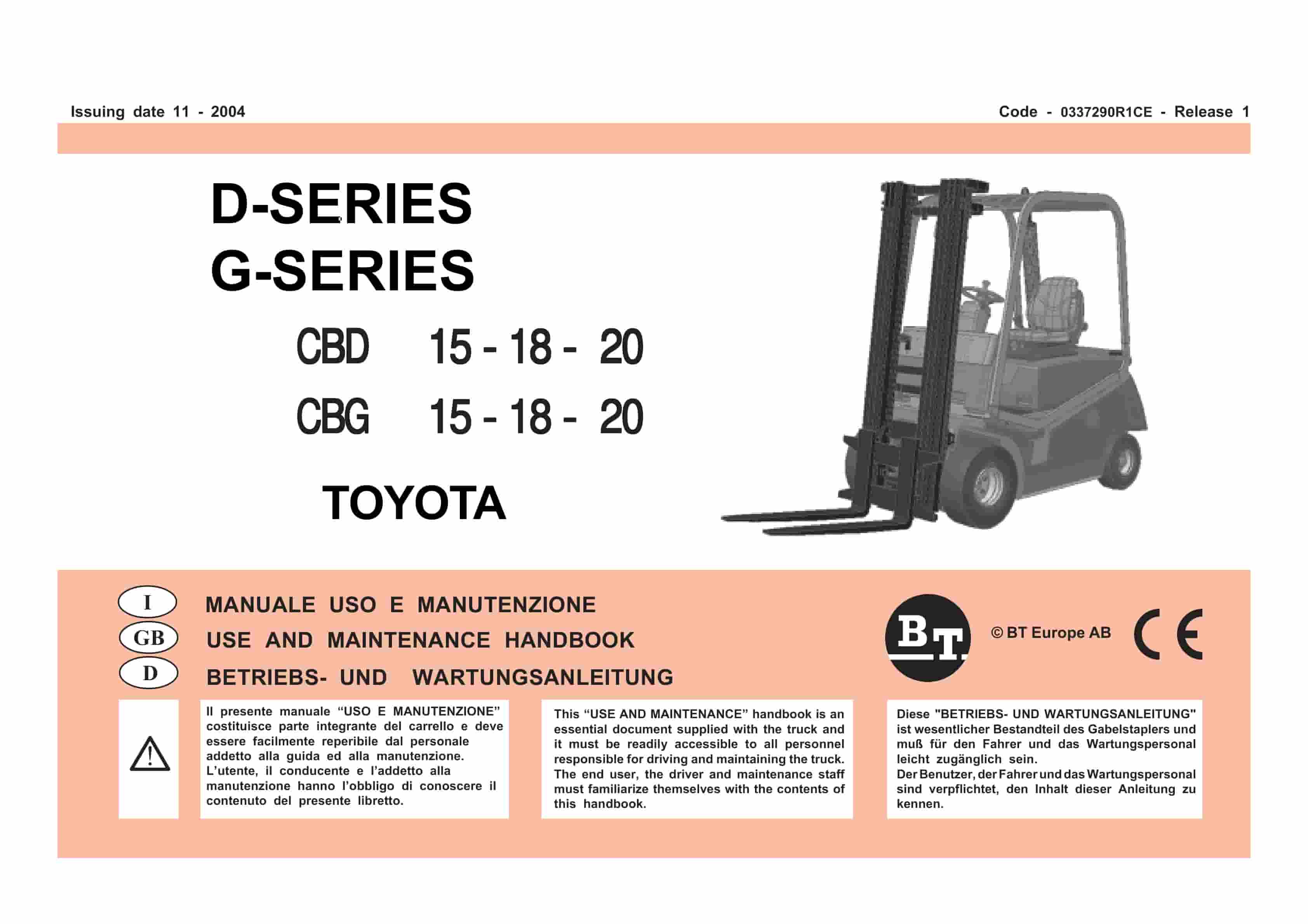
BT D-G-Series CBD15, CBD18, CBD20, CBG15, CBG18, CBG20 Use And Maintenance Handbook 0337290R1CE
$30.00 Add to cart -
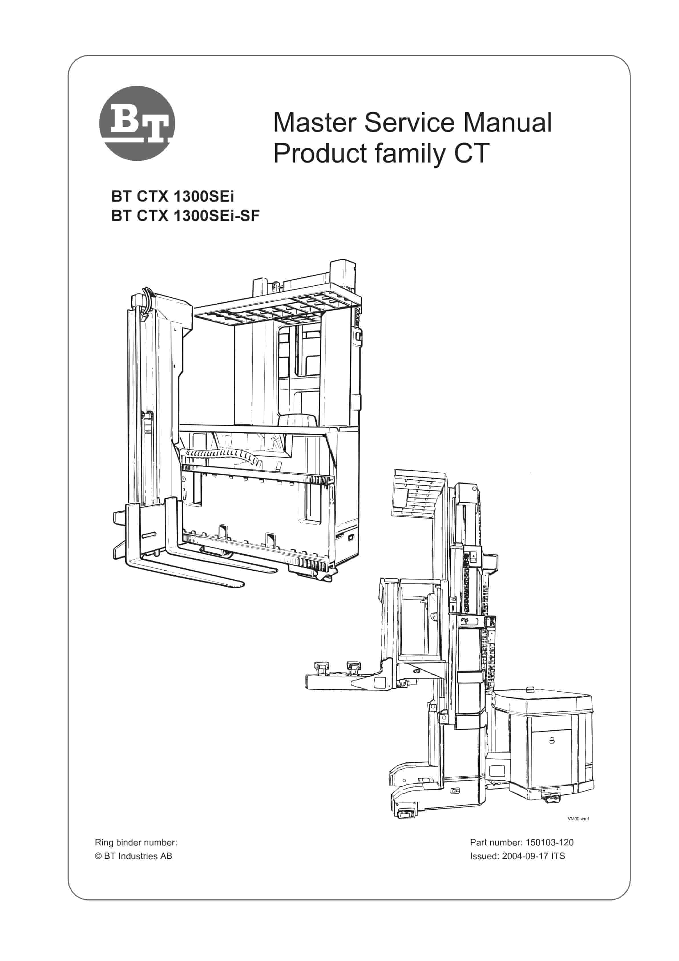
BT CTX 1300SEi, CTX 1300SEi SF Service Manual 150103-120
$30.00 Add to cart -
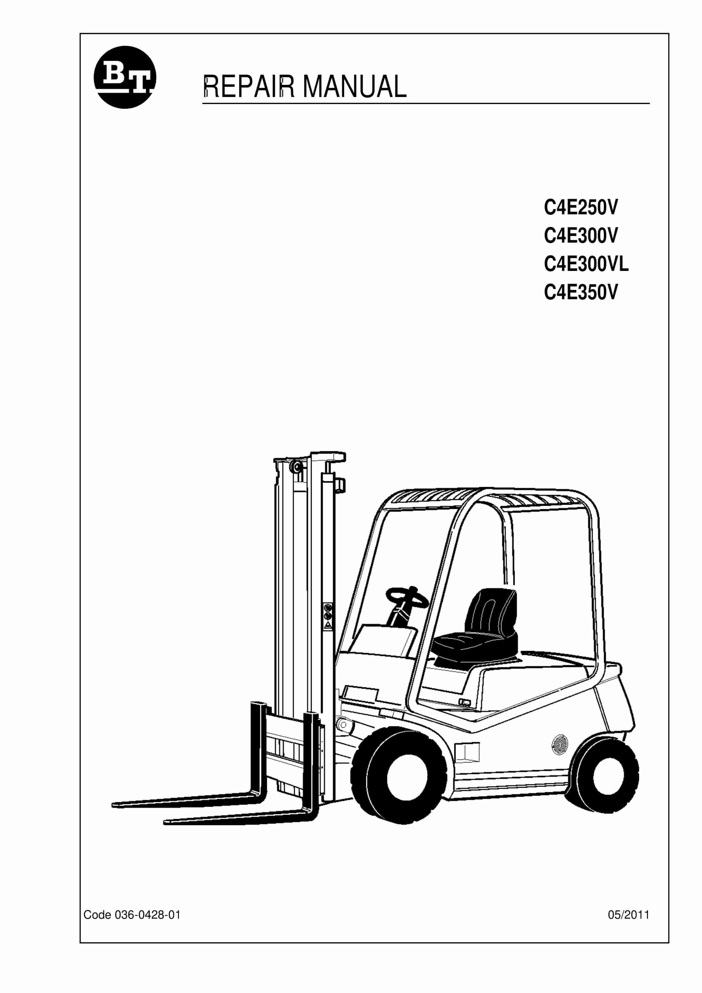
BT C4E250V, C4E300V, C4E300VL, C4E350V Repair Manual 036-0428-01
$30.00 Add to cart -
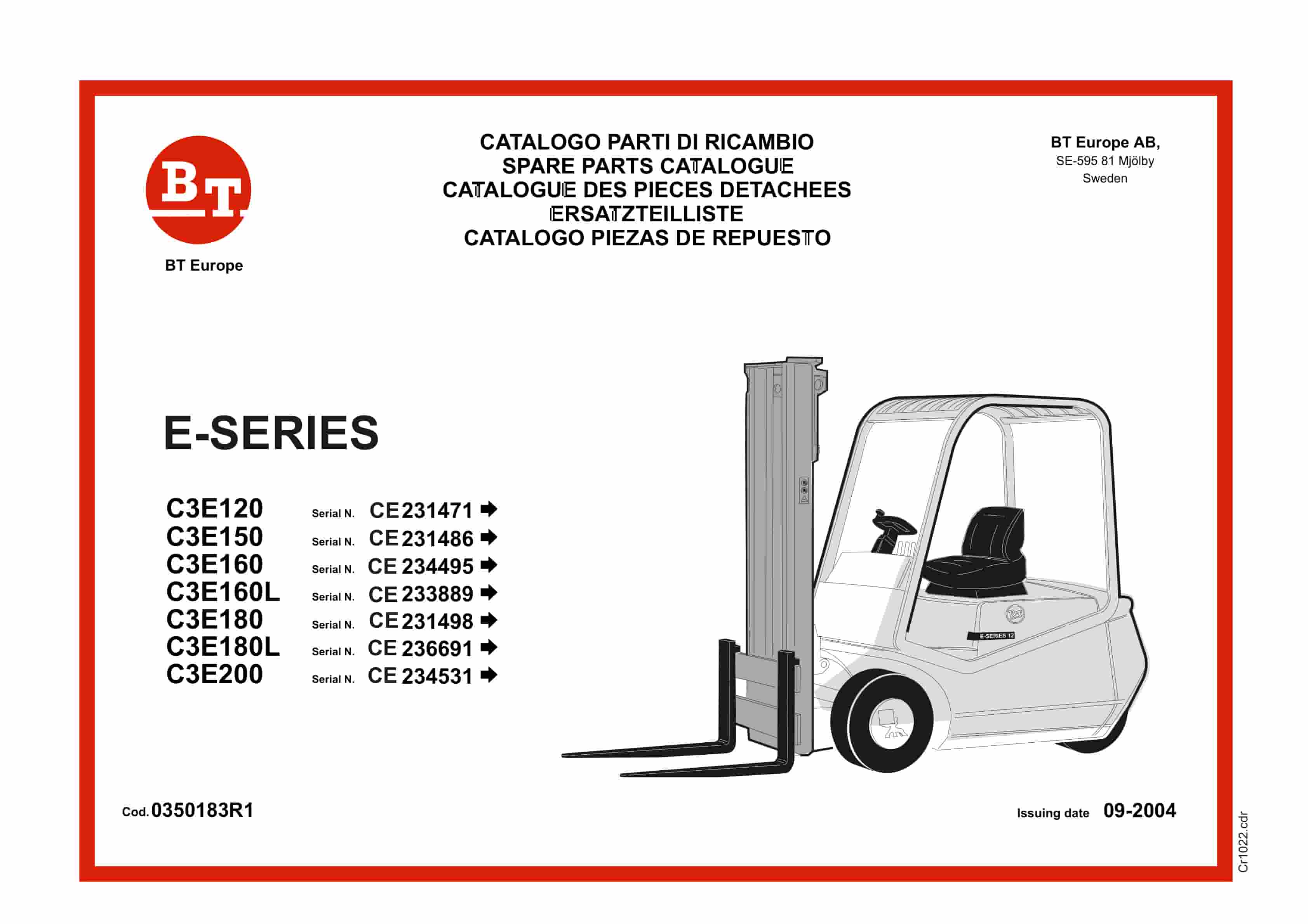
BT E-Series C3E120 to C3E200 Service Manual 0350183R1
$30.00 Add to cart -
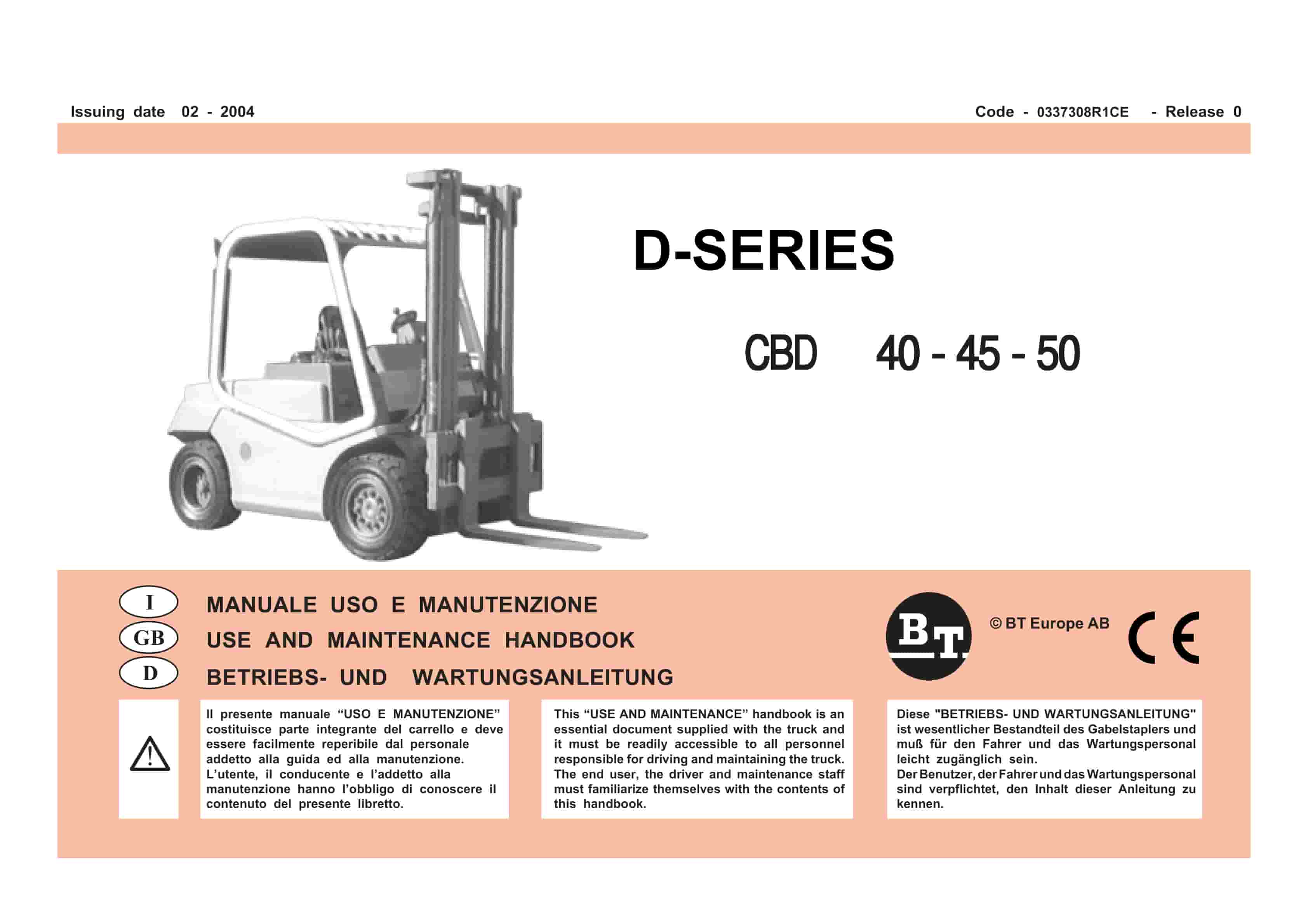
BT D-Series CBD40, CBD45, CBD50 Use And Maintenance Handbook 0337308R1CE
$30.00 Add to cart