


BT Vector C12.5 Service Manual 200422-040
$30.00
- Type Of Manual: Service Manual
- Manual ID: 200422-040
- : Service Manual PDF
- Number of Pages: 332
- Size: 7.7MB
- Format: PDF
Product details
-
Model List:
- Vector C12.5
- 1. Table of Contents
- 1.1. Chapt. Theme
- 1.2. Comissioning
- 1.3. Technical Description
- 1.4. Mechanics
- 1.5. Hydraulics
- 1.6. Electrial Equipment
- 1.7. Sensors
- 1.8. System Messages
- 1.9. Equipment Check
- 1.10. Inputs, Outputs, flags
- 1.11. Service Parameters
- 1.12. Operating Diagrams
- 1.13. Hydraulic Diagrams
- 1.14. Driving-/ Lifting-/ Steering Control
- 1.15. Abbrevations
- 2. Commissioning
- 2.1. Required measuring instruments and test equipment
- 2.2. Chapt. Theme Page
- 2.3. General 3
- 2.4. Loose parts 3
- 2.5. Basic truck 3
- 2.6. Hoist frame 4
- 2.7. Load-lifting device (LAM) 4
- 2.8. Battery equipment 5
- 2.9. Hydraulics 5
- 2.10. Supplied documentation 6
- 2.11. General
- 2.12. Loose parts
- 2.13. Basic truck
- 2.14. Hoist frame
- 2.15. Load-lifting device (LAM)
- 2.16. Battery equipment
- 2.17. Hydraulics
- 2.18. Supplied documentation
- 3. Technical Description
- 3.1. Chapt. Theme Page
- 3.2. Assembly arrangement 3
- 3.3. Components of the electrical
- 3.4. system 3
- 3.5. Components in the drive
- 3.6. compartment (rear view) 5
- 3.7. Components in the drive
- 3.8. compartment (right view 6
- 3.9. Technical data 7
- 3.10. Assembly arrangement
- 3.11. Components of the electrical system
- 3.12. Components in the drive compartment (rear view)
- 3.13. Components in the drive compartment (right view)
- 3.14. Technical data
- 4. Mechanics
- 4.1. Required measuring instruments and test equipment
- 4.2. Safety instructions 3
- 4.3. Gas pressure springs 5
- 4.4. Torque values for screwed connections 5
- 4.5. Hoist frame and cabin 5
- 4.6. Chassis 8
- 4.7. Load-bearing axles 9
- 4.8. Load wheel brake 11
- 4.9. Mechanically released spring pressure brake 13
- 4.10. Drive unit 15
- 4.11. Swivelling forks 16
- 5. Hydraulics
- 5.1. Chapt. Theme Page
- 5.2. Torques for hydraulic conus connections 3
- 5.3. Standard hydraulic diagrams 3
- 5.4. Safety instructions 4
- 5.5. Description of the hydraulic installation 4
- 5.6. Hydraulic installation on the chassis 6
- 5.7. Hydraulic installation in the rear of the truck 7
- 5.8. Tank 9
- 5.9. Fill- and ventilation filter 10
- 5.10. Return flow filter 11
- 5.11. Pump 12
- 5.12. Lifting module block 13
- 5.13. Lift cylinders (Main- and Auxiliary lift) 16
- 5.14. Hydraulic installation swivelling forks (SSG) 21
- 5.15. Torques for hydraulic conus connections
- 5.16. Standard hydraulic diagrams
- 5.17. Safety instructions
- 5.18. Description of the hydraulic installation
- 5.19. Hydraulic installation on the chassis
- 5.20. Hydraulic installation in the rear of the truck
- 5.21. Tank
- 5.22. Fill- and ventilation filter
- 5.23. Return flow filter
- 5.24. Pump
- 5.25. Lifting module block
- 5.26. Lift cylinders (Main- and Auxiliary lift)
- 5.27. Hydraulic installation swivelling forks (SSG)
- 6. Electrical equipment
- 6.1. Chapt. Theme Page
- 6.2. Block Diagram of the Control Concept 5
- 6.3. CAN-bus description 6
- 6.4. CAN-bus- features 6
- 6.5. Components of the control systems 7
- 6.6. Design of the Right Control Panel(UDR) 12
- 6.7. Design of the Left Control Panel (UDL) 15
- 6.8. Braking System 17
- 6.9. Driving 23
- 6.10. Steering 25
- 6.11. Triggering of the pump unit 27
- 6.12. Proportional controllers 28
- 6.13. Functional relations 31
- 6.14. Aisle recognition 35
- 6.15. The service menu 36
- 6.16. Release of Options via Code Numbers 36
- 6.17. End of aisle safety device (Option) 37
- 6.18. Function Description 37
- 6.19. Inductive guidance (WG) 38
- 6.20. Interface for the Connection of a Personnel Protection System (PSA) 50
- 6.21. Automatic swivelling / side shift synchronization 52
- 6.22. Battery discharge monitor 56
- 6.23. Hour meters 57
- 6.24. Cut-outs 57
- 6.25. Software administration 59
- 6.26. Block diagram of the control concept
- 6.27. CAN-bus description
- 6.28. Components of the control systems
- 6.29. Design of the Right Control Panel (UDR)
- 6.30. Design of the left control panel (UDL)
- 6.31. Braking System
- 6.32. Driving
- 6.33. Steering
- 6.34. Triggering of the pump unit
- 6.35. Proportional controllers
- 6.36. Functional relations
- 6.37. Aisle recognition
- 6.38. The service menu
- 6.39. Release of Options via Code Numbers
- 6.40. End of aisle safety device (GESI) (Option)
- 6.41. Function Description
- 6.42. Inductive guidance (WG)
- 6.43. Interface for the Connection of a Personnel Protection System (PSA)
- 6.44. Automatic swivelling / side shift synchronization
- 6.45. Battery discharge monitor
- 6.46. Hour meters
- 6.47. Cut-outs
- 6.48. Software administration
- 7. Sensors
- 7.1. Required measuring instruments and test equipment
- 7.2. Chapt. Theme Page
- 7.3. Sensor units main lift 3
- 7.4. Sensor units main lift
- 7.5. Potentiometer and incremental transmitter
- 7.6. Assembly
- 7.7. Checking the adjustment of the potentiometer
- 7.8. Calibration (Teach- In)
- 7.9. Checking the tension of the toothed belt
- 7.10. Reference switch 0,3 m
- 7.11. Assembly
- 7.12. Startup and check of the main lift sensor units
- 7.13. Checking the 0,3 m-switch
- 7.14. Sensor units actual value steering
- 7.15. Sensor elements
- 7.16. Demounting the incremental transmitter (9)
- 7.17. Mounting the incremental transmitter (9)
- 7.18. Assembly and mechanical adjustment of the potentiometer (10)
- 7.19. Checking the adjustment of the potentiometer
- 7.20. Electrical setting
- 7.21. correction value – (value written down)
- 7.22. Checking the adjustment of the steering sensor unit
- 7.23. Checking of the exact center position and fine-adjustment
- 7.24. Trucks with wire guidance
- 7.25. Check WG-steering functions
- 7.26. Sensor bearings drive and pump motor
- 7.27. Exchanging a sensor bearing
- 7.28. Temperature sensor drive and pump motor
- 7.29. Mounting of a new temperature sensor
- 7.30. Sensor unit auxiliary lift
- 7.31. Sensor element
- 7.32. Assembly and mechanical adjustment
- 7.33. Checking the potentiometer-adjustment
- 7.34. Calibration (Teach- In)
- 7.35. Checking the settings
- 7.36. Sensor unit side shift
- 7.37. Sensor element
- 7.38. Assembly and mechanical adjustment
- 7.39. Measure the potentiometer setting
- 7.40. Calibration (Teach- In)
- 7.41. Checking the settings
- 7.42. Sensor unit swivelling
- 7.43. Sensor element
- 7.44. Assembly and mechanical adjustment
- 7.45. Measuring of the potentiometer-setting
- 7.46. Calibration (Teach- In)
- 7.47. Checking the settings
- 7.48. Sensor unit for load detection
- 7.49. Sensor element
- 7.50. Assembly and mechanical adjustment
- 7.51. Disassembly of the spring (2)
- 7.52. Measuring the potentiometer setting
- 7.53. Calibration
- 7.54. Checking the setting
- 8. System messages
- 8.1. Required measuring instruments and test equipment
- 8.2. Chapt. Theme Page
- 8.3. Remarks for systematic error diagnosis 3
- 8.4. Startup message 9
- 8.5. Operation messages VZA 16
- 8.6. Remarks for systematic error diagnosis
- 8.7. Startup messages
- 8.8. Operation messages VZA
- 9. Equipment check
- 9.1. Required measuring instruments and test equipment
- 9.2. Chapt. Theme Page
- 9.3. Visual inspection of electronic assemblies 3
- 9.4. Interchanging electronic assemblies 5
- 9.5. CAN Check 14
- 9.6. RS232-Check 18
- 9.7. VZ-Check 21
- 9.8. Check of Control Panel 28
- 10. Inputs, outputs, tags
- 10.1. Chapt. Theme Page
- 10.2. Assignment of the operands to VZA and VZK 3
- 10.3. Inputs 5
- 10.4. Outputs 9
- 10.5. Tags 12
- 10.6. Control status VZK 22
- 10.7. Control system states of the VZK 32
- 10.8. Assignment of the operands to VZA and VZK
- 10.9. Inputs
- 10.10. Outputs
- 10.11. Tags
- 10.12. Status Tags VZA
- 10.13. Control system states of the VZK
- 11. Service parameters
- 11.1. Required measuring instruments and test equipment
- 11.2. Service display configuration
- 11.3. Service menu / setting parameters
- 12. Operating Diagrams
- 13. Hydraulic Diagram
- 14. Driving- / Lifting- /Steering control
- 14.1. LED flashing codes
- 14.2. Table of error numbers and LED flashing codes
- 14.3. LED flashing codes
- 15. Abbreviations
- 15.1. Abbr./term
- 15.2. Meaning
Related products
-
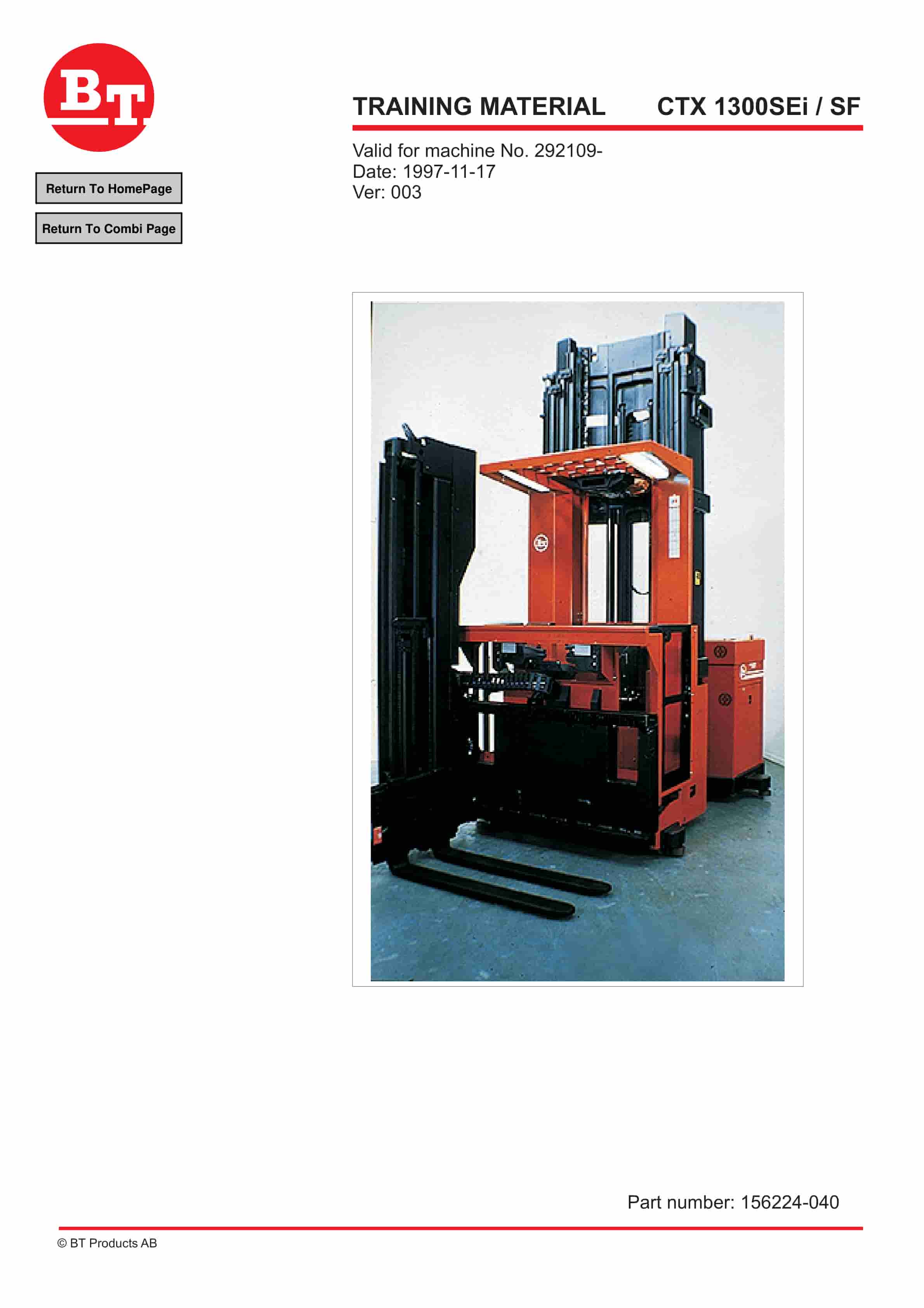
BT CTX 1300SEi, CTX 1300SEi SF Training Material 156224-040
$30.00 Add to cart -
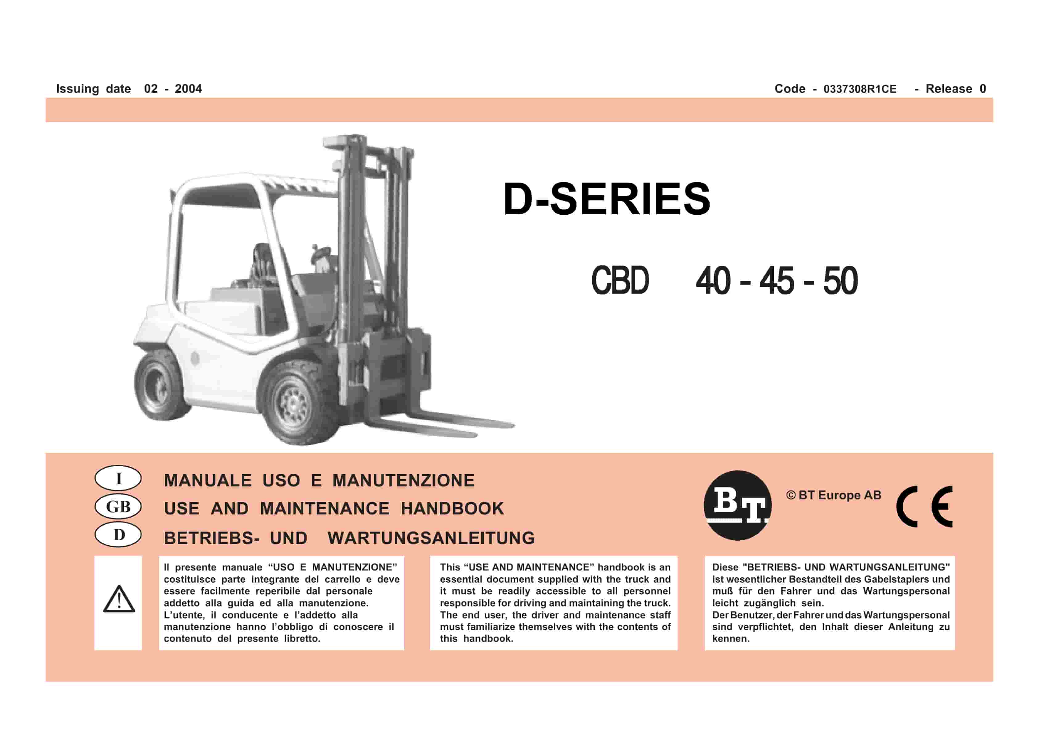
BT D-Series CBD40, CBD45, CBD50 Use And Maintenance Handbook 0337308R1CE
$30.00 Add to cart -
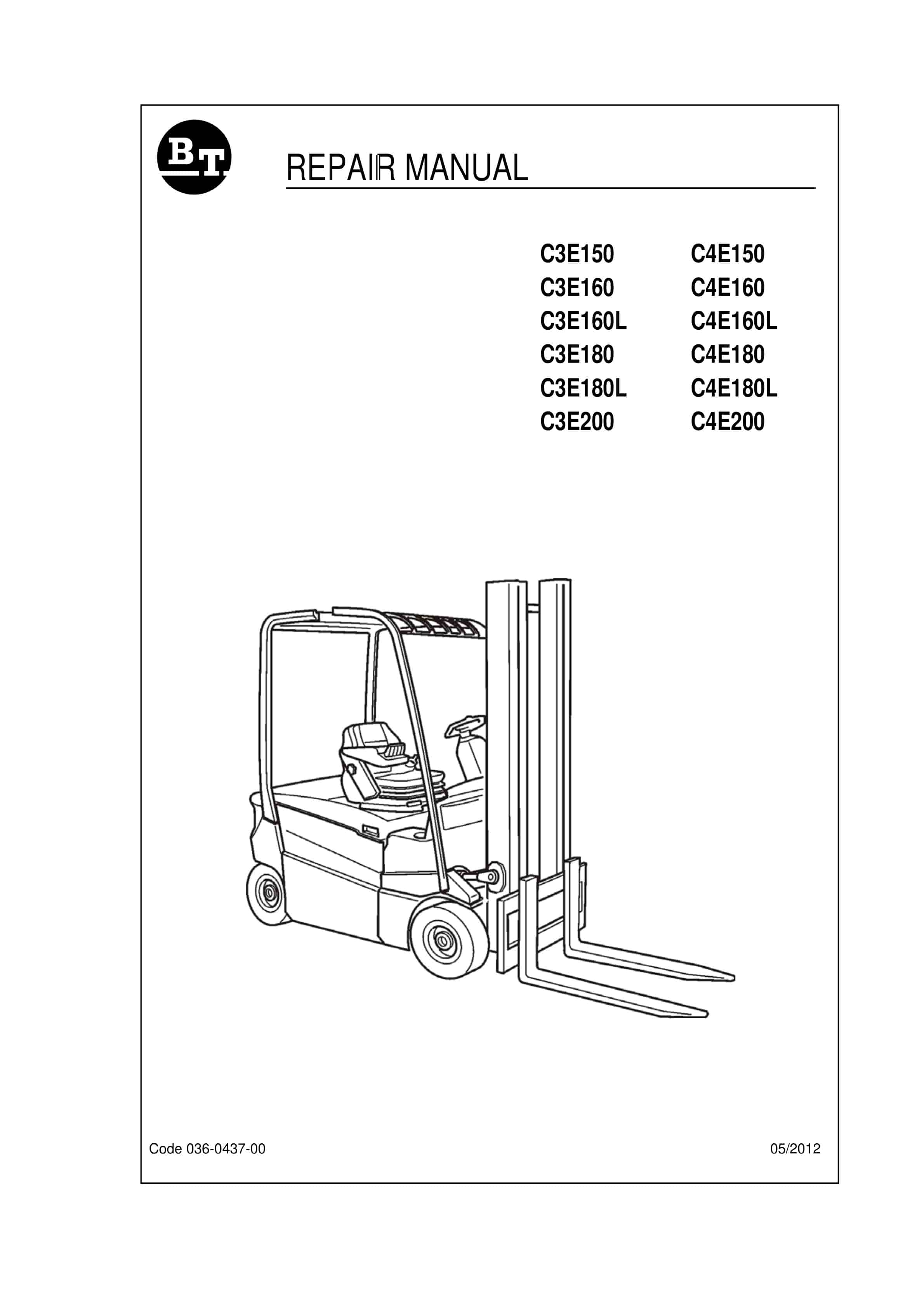
BT C3E150 to C4E200 Repair Manual 036-0437-00
$30.00 Add to cart -
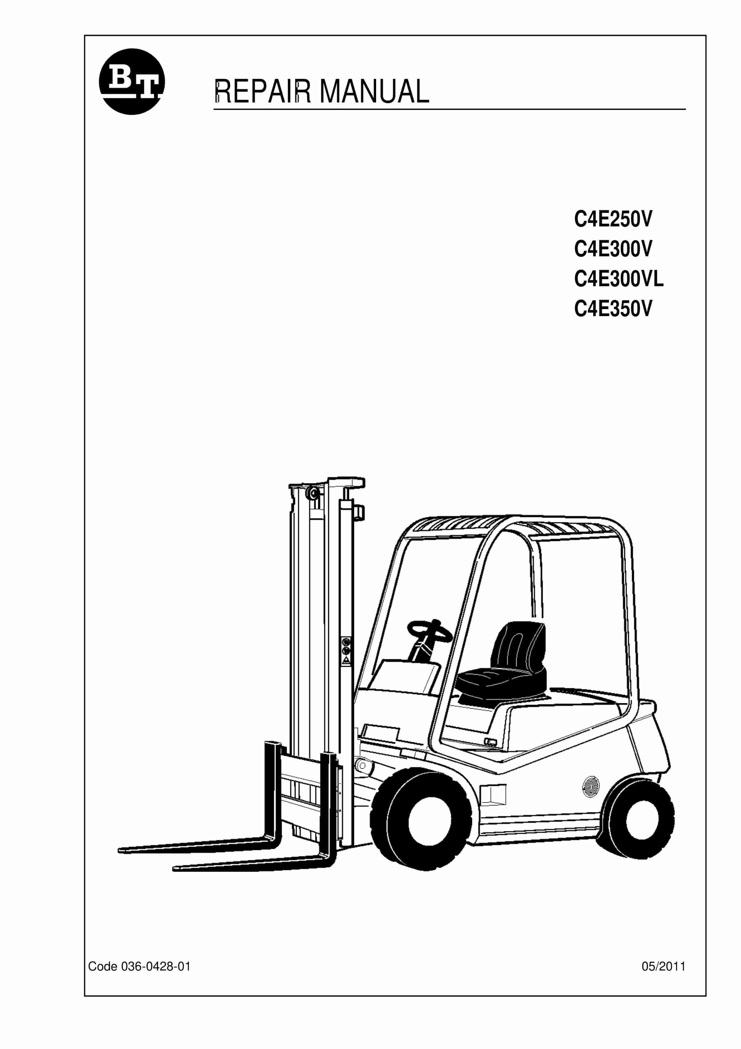
BT C4E250V, C4E300V, C4E300VL, C4E350V Repair Manual 036-0428-01
$30.00 Add to cart -
BT C3E120 to C4E200 Service Manual 036-0410-07
$30.00 Add to cart