


BT Veflex VR, VR SF, VRE150, VRE125SF Service Manual 244989-040
$30.00
- Type Of Manual: Service Manual
- Manual ID: 244989-040
- : Service Manual PDF
- Number of Pages: 682
- Size: 21.8MB
- Format: PDF
Product details
-
Model List:
- Veflex VR, VR SF, VRE150, VRE125SF
- 1. Table of contents
- 2. Technical data
- 3. Maintenance
- 3.1. Introduction and safety, maintenance
- 3.2. Safety regulations during maintenance work
- 3.2.1. Tilting the cab up on a cold store truck
- 3.2.2. Tilting the cab down on a cold store truck
- 3.3. Cleaning and washing
- 3.3.1. External cleaning
- 3.3.2. Cleaning the motor compartment
- 3.3.3. Electrical components
- 3.4. Safe lifting
- 3.5. Maintenance chart
- 3.5.1. VRE150, VRE125SF
- 3.5.2. VR SF/VRE125SF
- 3.5.3. VR/VRE150
- 3.5.4. VR SF/VR
- 3.5.5. VRE150/VRE125SF
- 3.5.6. VR SF/VRE125SF
- 3.5.7. VR/VRE150
- 3.5.8. VR/VRE150
- 3.6. Oil and grease specifications
- 4. Tools
- 4.1. Electrical contacts
- 4.1.1. Super Seal contacts
- 4.1.2. AMP contacts
- 4.2. Miscellaneous tools
- 5. Chassis – 0000
- 5.1. General
- 5.2. List of tools
- 5.3. Transporting the truck
- 5.4. Assembling the mast
- 5.5. Installation in narrow aisles
- 5.5.1. General
- 5.5.2. Track-guided truck
- 5.5.3. Wire guided truck
- 5.5.4. General adjustment
- 6. Frame, mounted components – 0400
- 6.1. General tightening torque
- 6.1.1. Galvanised, non oiled bolts
- 6.1.2. Untreated, oiled bolts
- 7. Driver Protection – 0840
- 7.1. General
- 7.2. Tilt Stops
- 7.2.1. Inspection and Adjustment
- 8. Electric Pump Motor – 1710
- 8.1. General
- 8.2. Dismantling the Pump Motor
- 8.3. Removing and Replacing the Pump Motor
- 8.3.1. Dismantling
- 8.3.2. Assembling
- 8.4. Bearing Replacement
- 8.4.1. Dismantling
- 8.4.2. Re-Assembly
- 8.5. Installation Instructions for External Temperature Sensor
- 9. Electric Steering Motor – 1730
- 9.1. General
- 9.2. Replacing the Steering Motor
- 9.2.1. Dismantling
- 9.2.2. Re-Assembly
- 9.3. Removing and Replacing the Carbon Brushes
- 10. Electric Drive Motor – 1760
- 10.1. General
- 10.2. Dismantling the Drive Motor
- 10.3. Dismantling and Assembling the Drive Motor
- 10.3.1. Dismantling the Drive Motor
- 10.3.2. Assembling the Drive Motor
- 10.4. Bearing Replacement
- 10.4.1. Dismantling
- 10.4.2. Assembling
- 10.5. Installation Instructions for External Temperature Sensor
- 11. Mechanical Drive Gear Unit – 2550
- 11.1. General
- 11.2. Drive/Transmission Assemblys Main Components and Technical Data
- 11.2.1. Position of Components
- 11.2.2. Technical data
- 11.2.3. Dismantling the Transmission
- 11.3. Replacing the Drive Motor/Drive Transmission
- 11.3.1. Dismantling the Drive Motor
- 11.3.2. Removal of the Drive Transmission
- 11.3.3. Assembling the Drive Transmission
- 11.3.4. Installing the Drive Motor
- 11.4. Checking/Replacing the Oil
- 11.4.1. Checking/Refilling the Oil
- 11.4.2. Changing the Oil
- 11.5. Repairs
- 11.5.1. Replacing the Drive Shaft Gasket
- 11.5.2. Leakage from the Upper Cover
- 11.5.3. Leakage from the Lower Cover
- 11.5.4. Replacing Wheel Bolts
- 12. Travel brake system – 3100
- 12.1. Brake system
- 12.1.1. General
- 12.2. Description of function
- 12.2.1. Releasing the accelerator
- 12.2.2. Changing travel direction
- 12.2.3. Pressing the brake pedal (without support arm brake)
- 12.2.4. Pressing the brake pedal (with support arm brakes)
- 12.2.5. Parking brake
- 12.2.6. Emergency braking
- 12.3. Electromechanical disc brake, drive motor
- 12.4. Disassembly
- 12.5. Inspection
- 12.6. Assembly
- 12.7. Maintenance
- 12.7.1. Adjusting the play
- 12.7.2. Wear
- 12.7.3. Checking the braking force
- 12.8. Multiple disc brake, support arm
- 12.8.1. Assembly
- 12.8.2. Dismantling
- 12.8.3. Maintenance
- 13. Drive wheel – 3530
- 13.1. General
- 13.2. Dismantling the drive wheel
- 13.3. Assembling the drive wheel
- 14. Fork/support arm wheel – 3550
- 14.1. General
- 14.2. Dismantling the wheel
- 14.3. Assembling the wheel
- 14.4. Dismantling/assembling the wheel bearings
- 14.4.1. Dismantling the bearing
- 14.4.2. Assembling the bearing
- 15. Electric steering wheel/lever – 4310
- 15.1. General
- 15.2. Replacement of the steering generator
- 15.2.1. Dismantling
- 15.2.2. Assembly
- 16. Steering angle sensor – 4350
- 16.1. General
- 16.2. Procedure
- 16.2.1. Adjustment of directional sensor
- 16.2.2. Adjustment of the steering angle sensor
- 17. Automatic steering system – 4500
- 17.1. General
- 17.2. Generator
- 17.2.1. Technical data
- 17.3. Wire guidance system overview
- 17.4. Wire guidance components
- 17.4.1. Antennae, W1, W2
- 17.4.2. Control unit, A3
- 17.4.3. Home position sensor, S85
- 17.4.4. Steering angle sensor, U15
- 17.4.5. Diverse
- 17.5. Operating description
- 17.5.1. Run mode
- 17.5.2. Service mode
- 17.5.3. Parameter 36
- 17.5.4. Parameter 71
- 17.5.5. Parameter 72
- 17.5.6. Parameter 73
- 17.5.7. Parameter 74
- 17.5.8. Parameter 75
- 17.6. Error Codes
- 17.6.1. Error codes detected by electronic card A5
- 17.6.2. Error code detected by electronic card A3, WG-control unit
- 18. Electrical System – 5000.1
- 18.1. General
- 18.2. Electronics Card, traction controller A1 and lift controller A2
- 18.2.1. General
- 18.2.2. Terminal Connections and Pole Bolts
- 18.2.3. Technical Data
- 18.2.4. Installation of New Controller on Truck
- 18.2.5. Programming
- 18.3. Electronics Card, Fork Apparatus, A4
- 18.3.1. General
- 18.3.2. Terminal Connections
- 18.3.3. Installation of New Card on Truck
- 18.3.4. Programming
- 18.4. Electronics Card, Main Card, A5
- 18.4.1. General
- 18.4.2. Terminal Connections and Voltages on A5
- 18.4.3. Installation of New Card on Truck
- 18.4.4. Programming
- 18.5. Electrical System, Overview
- 18.6. Symbol List and Wiring Diagrams
- 18.6.1. Symbol List
- 18.6.2. Wiring diagrams VR SF
- 18.6.3. Wiring diagrams VR
- 18.6.4. Component List, standard truck
- 18.6.5. Component identification
- 18.7. Functional Description
- 18.7.1. Key in Position 0
- 18.7.2. Key in Position I, Driver Seated
- 18.7.3. Direction of Travel Selection
- 18.7.4. Driving
- 18.7.5. Travel speeds
- 18.7.6. Steering
- 18.7.7. Braking
- 18.7.8. Aisle-End Slowdown
- 18.7.9. Fork Lifting
- 18.7.10. Height Indication
- 18.7.11. Lift height limit
- 18.7.12. Height Pre-Set
- 18.7.13. Fork Lowering
- 18.7.14. Lateral Movement/Traversing of Forks (VR SF)
- 18.7.15. Lateral Movement/Traversing of Forks (VR)
- 18.7.16. Rotating the Forks (VR)
- 18.7.17. Simultaneous Traversing and Rotation Movement (VR)
- 18.7.18. Extra Hydraulic Functions (VR)
- 18.7.19. Weighing
- 18.7.20. Driver Identification
- 18.8. Parameter
- 18.8.1. Parameter Settings
- 18.8.2. Parameter 1
- 18.8.3. Parameter 2
- 18.8.4. Parameter 3
- 18.8.5. Parameter 4
- 18.8.6. Parameter 5
- 18.8.7. Parameter 6
- 18.8.8. Parameter 7
- 18.8.9. Parameter 8
- 18.8.10. Parameter 10
- 18.8.11. Parameter 11
- 18.8.12. Parameter 12
- 18.8.13. Parameter 13
- 18.8.14. Parameter 14
- 18.8.15. Parameter 15
- 18.8.16. Parameter 16
- 18.8.17. Parameters 17 and 18
- 18.8.18. Parameter 19
- 18.8.19. Parameter 20
- 18.8.20. Parameter 21
- 18.8.21. Parameter 22
- 18.8.22. Parameter 23
- 18.8.23. Parameter 24
- 18.8.24. Parameter 25
- 18.8.25. Parameter 26
- 18.8.26. Parameter 27
- 18.8.27. Parameter 28
- 18.8.28. Parameter 29
- 18.8.29. Parameter 35
- 18.8.30. Parameter 36
- 18.8.31. Parameter 37
- 18.8.32. Parameter 38
- 18.8.33. Parameter 39
- 18.8.34. Parameters 40 to 42
- 18.8.35. Parameter 43
- 18.8.36. Parameter 44
- 18.8.37. Parameter 45
- 18.8.38. Parameter 46
- 18.8.39. Parameter 47 (VR)
- 18.8.40. Parameter 48 (VR)
- 18.8.41. Parameter 49 (VR SF)
- 18.8.42. Parameter 50
- 18.8.43. Parameter 51 (VR)
- 18.8.44. Parameter 53 (VR)
- 18.8.45. Parameter 54
- 18.8.46. Parameter 55
- 18.8.47. Parameter 56 (VR)
- 18.8.48. Parameter 57
- 18.8.49. Parameter 58 (VR)
- 18.8.50. Parameter 59 (VR)
- 18.8.51. Parameter 60 (VR)
- 18.8.52. Parameter 61 (VR)
- 18.8.53. Parameter 62 (VR)
- 18.8.54. Parameter 63 (VR)
- 18.8.55. Parameter 64 (VR)
- 18.8.56. Parameter 65 (VR)
- 18.8.57. Parameter 66 (VR)
- 18.8.58. Parameter 67
- 18.9. Instrument Panel and Display
- 18.9.1. Show
- 18.9.2. Operating Time
- 18.9.3. Programming
- 18.10. Codes
- 18.10.1. Warning Codes
- 18.10.2. Error mode
- 18.10.3. Safety Logic
- 18.10.4. Warning Codes without Registration
- 18.10.5. Warning Codes with Registration
- 18.10.6. Error Codes
- 18.10.7. Error Codes with Registration
- 19. Electrical systems – 5000.2
- 19.1. General
- 19.1.1. VRE125SF
- 19.2. Logic card, drive controller A1 and lift controller A2
- 19.2.1. General
- 19.2.2. Connection terminal and terminal pillars
- 19.2.3. Technical data
- 19.2.4. Installing a new logic card in the truck
- 19.2.5. Programming
- 19.3. Logic card, fork unit, A4
- 19.3.1. General
- 19.3.2. Connector plug
- 19.4. Logic card, main card, A5
- 19.4.1. General
- 19.4.2. Connection terminals and voltages on A5
- 19.5. Electric system, overview
- 19.5.1. VRE125SF
- 19.6. Symbol list and electric wiring diagram
- 19.6.1. Symbol list
- 19.6.2. Electric wiring diagrams VRE125SF
- 19.6.3. Electric wiring diagrams VRE150
- 19.6.4. Electric wiring diagrams, cold store cabins VRE150
- 19.6.5. Component list, standard truck
- 19.6.6. Component placement
- 19.7. Functional description
- 19.7.1. Truck not switched on
- 19.7.2. Truck switched on
- 19.7.3. Travel direction selection
- 19.7.4. Driving
- 19.7.5. Travel speeds
- 19.7.6. Steering
- 19.7.7. Braking
- 19.7.8. Aisle-end braking
- 19.7.9. Fork lifting
- 19.7.10. Height indication
- 19.7.11. Lift height limit supervision
- 19.7.12. Height preselection
- 19.7.13. Fork lowering
- 19.7.14. Sideshift/traversing of forks (VRE125SF)
- 19.7.15. Sideshift/traversing of forks (VRE150)
- 19.7.16. Fork rotation (VRE150)
- 19.7.17. Simultaneous traversing and rotation movement (VRE150)
- 19.7.18. Extra hydraulic function (VRE150)
- 19.7.19. Weight calculation
- 19.8. Display and programming
- 19.8.1. Keypad
- 19.9. Parameter setting of all parameters
- 19.9.1. Parameters
- 19.9.2. Parameter 19
- 19.9.3. Parameter 21
- 19.9.4. Parameter 38
- 19.10. Warning codes
- 19.11. Error codes
- 19.11.1. Error type
- 19.11.2. Safety logics
- 19.11.3. Warning code without recording
- 19.11.4. Warning codes with logging
- 19.11.5. Error codes with logging
- 19.12. Truck log system, code lock
- 19.12.1. General
- 19.12.2. SD 16
- 19.12.3. Components
- 19.13. I/O module
- 20. Hydraulic system – 6000
- 20.1. General
- 20.2. Hydraulic schematics
- 20.2.1. Symbols
- 20.2.2. Hydraulic schematics (VR SF)
- 20.2.3. Component description (VR SF)
- 20.2.4. Hydraulic schematics (VR)
- 20.2.5. Component description (VR)
- 20.3. Hydraulic components, positioning
- 20.3.1. Overview
- 20.3.2. Hydraulic unit
- 20.3.3. Hydraulic components in the fork unit (VR SF)
- 20.3.4. Hydraulic components in the fork unit (VR)
- 20.3.5. Cab tilt function (cold store cab)
- 21. Hydraulic pump – 6140
- 21.1. General
- 21.2. Replacing the hydraulic pump
- 21.2.1. Dismantling
- 21.2.2. Assembling
- 22. Hydraulic connections – 6230
- 22.1. General
- 22.2. Tightening torque for hydraulic connections
- 22.2.1. Conical connection with O-ring
- 22.2.2. Tredo seal
- 22.2.3. Pipe couplings
- 22.2.4. Connections screwed into aluminium
- 22.2.5. Connections screwed into steel
- 22.3. Quick connection
- 22.3.1. Assembling
- 22.3.2. Dismantling
- 23. Main lift chain system – 7120
- 23.1. General
- 23.2. Checking the chain setting
- 23.3. Chain inspection
- 23.3.1. Noise
- 23.3.2. Surface rust
- 23.3.3. Rusty links
- 23.3.4. Stiff links
- 23.3.5. Bolt rotation
- 23.3.6. Loose bolts
- 23.3.7. Outline wear
- 23.3.8. Stretching
- 23.3.9. Damage
- 23.3.10. Damaged discs
- 23.3.11. Damaged bolts
- 23.3.12. Dirty chain
- 23.4. Cleaning
- 23.5. Lubrication
- 24. Turret Head Fork Apparatus – 7700 (VR, VRE150)
- 24.1. General description
- 24.1.1. Main Components
- 24.1.2. Fork turning
- 24.1.3. Side-shift movement
- 24.2. Inspection and maintenance
- 24.2.1. External inspection
- 24.2.2. Inspection
- 24.2.3. Maintenance
- 24.3. Adjustment of turret head fork apparatus
- 24.3.1. Fork carriage, end position rotation
- 24.3.2. Setting tooth flank play
- 24.3.3. Adjusting the apparatus lateral play on the mast guide
- 24.3.4. Potentiometer for the turning movement
- 24.3.5. Inductive sensor for the home position, side-shift
- 24.4. Replacing components
- 24.4.1. Turning chain
- 24.4.2. Turning bearing
- 25. Shuttle fork unit – 7800 (VR SF, VRE125SF)
- 25.1. Maintenance
Related products
-
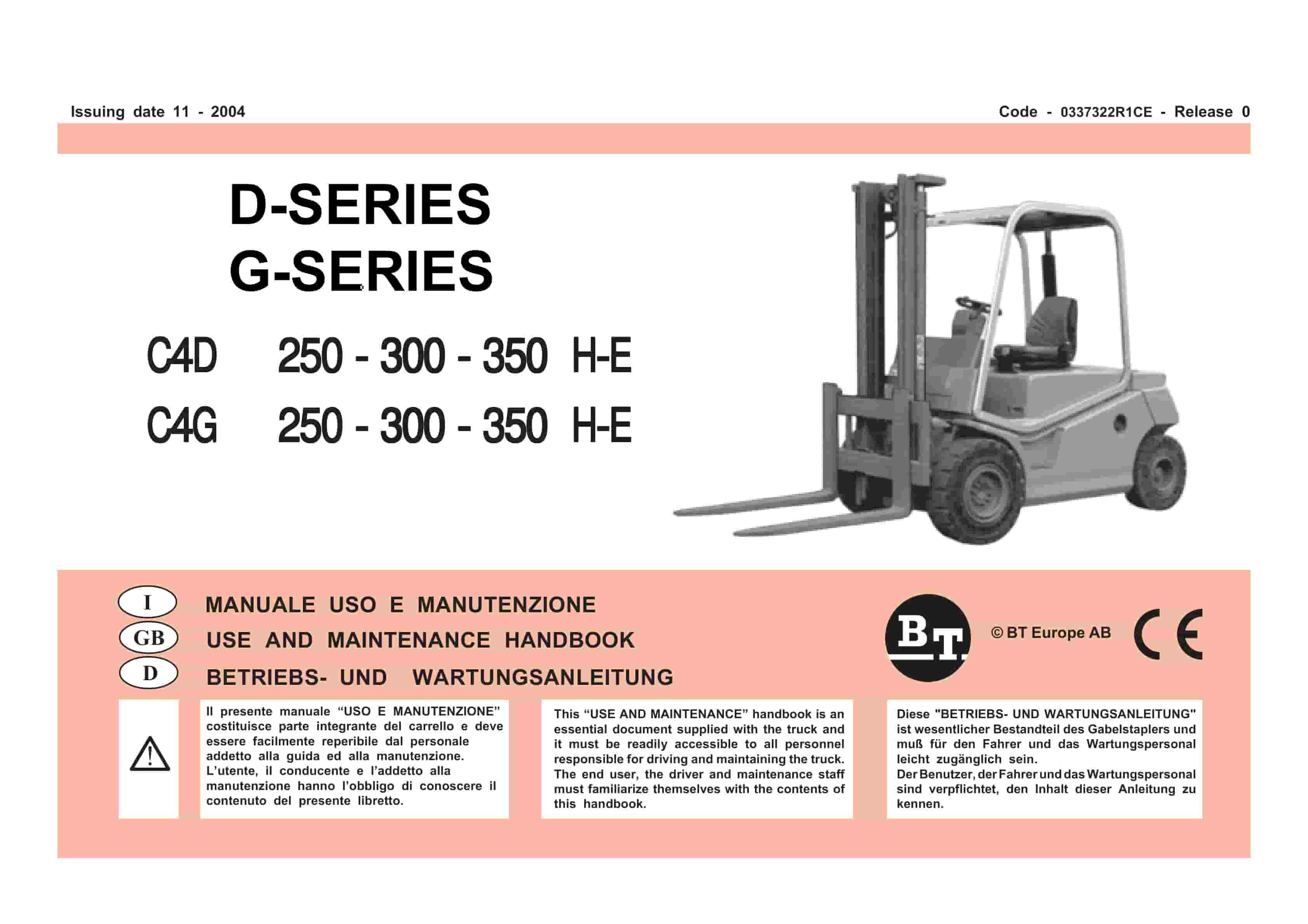
BT D-G-Series C4D250H-E, C4D300H-E, C4D350H-E, C4G250H-E, C4G300H-E, C4G350H-E Use And Maintenance Handbook 0337322R1CE
$30.00 Add to cart -
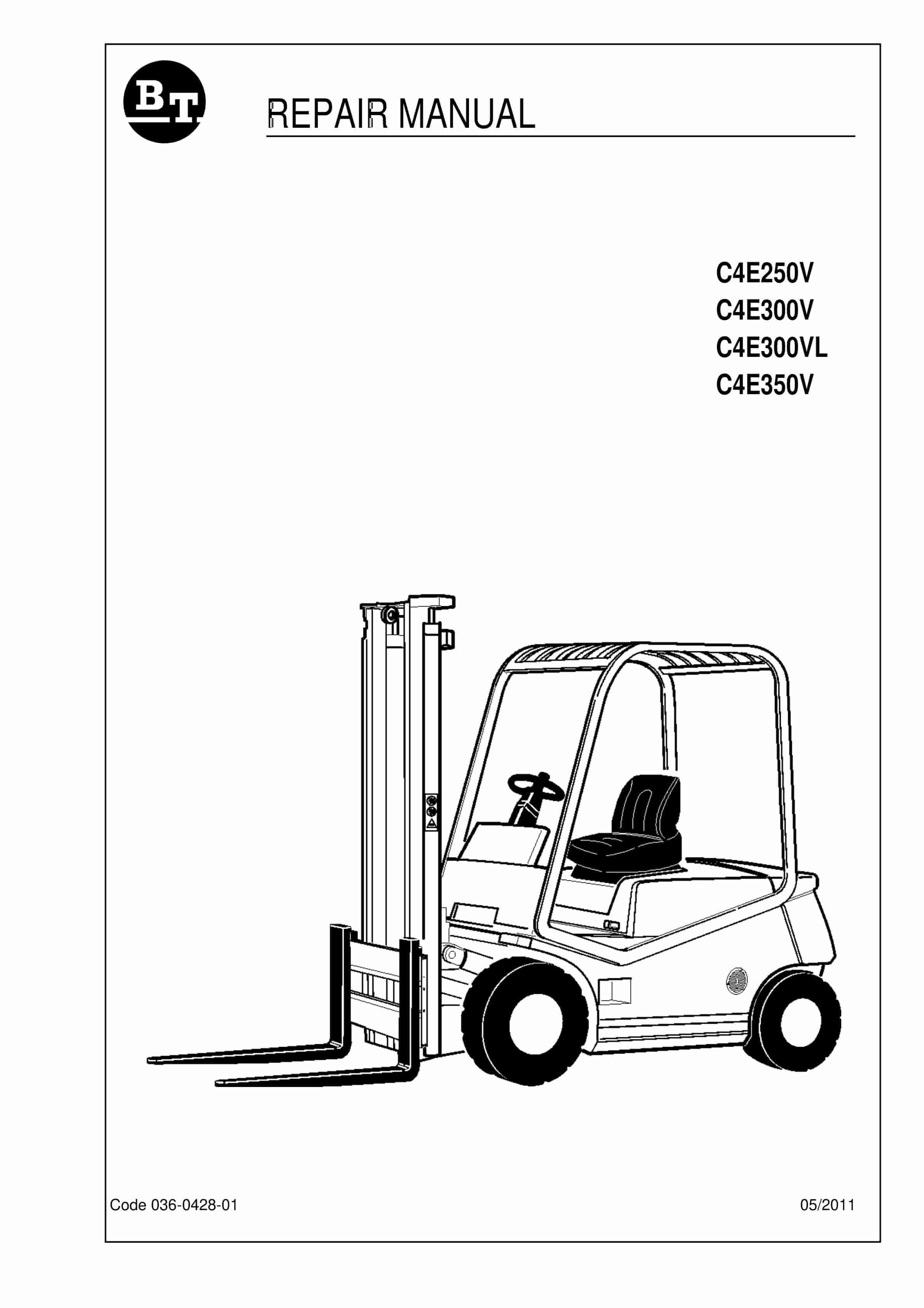
BT C4E250V, C4E300V, C4E300VL, C4E350V Repair Manual 036-0428-01
$30.00 Add to cart -
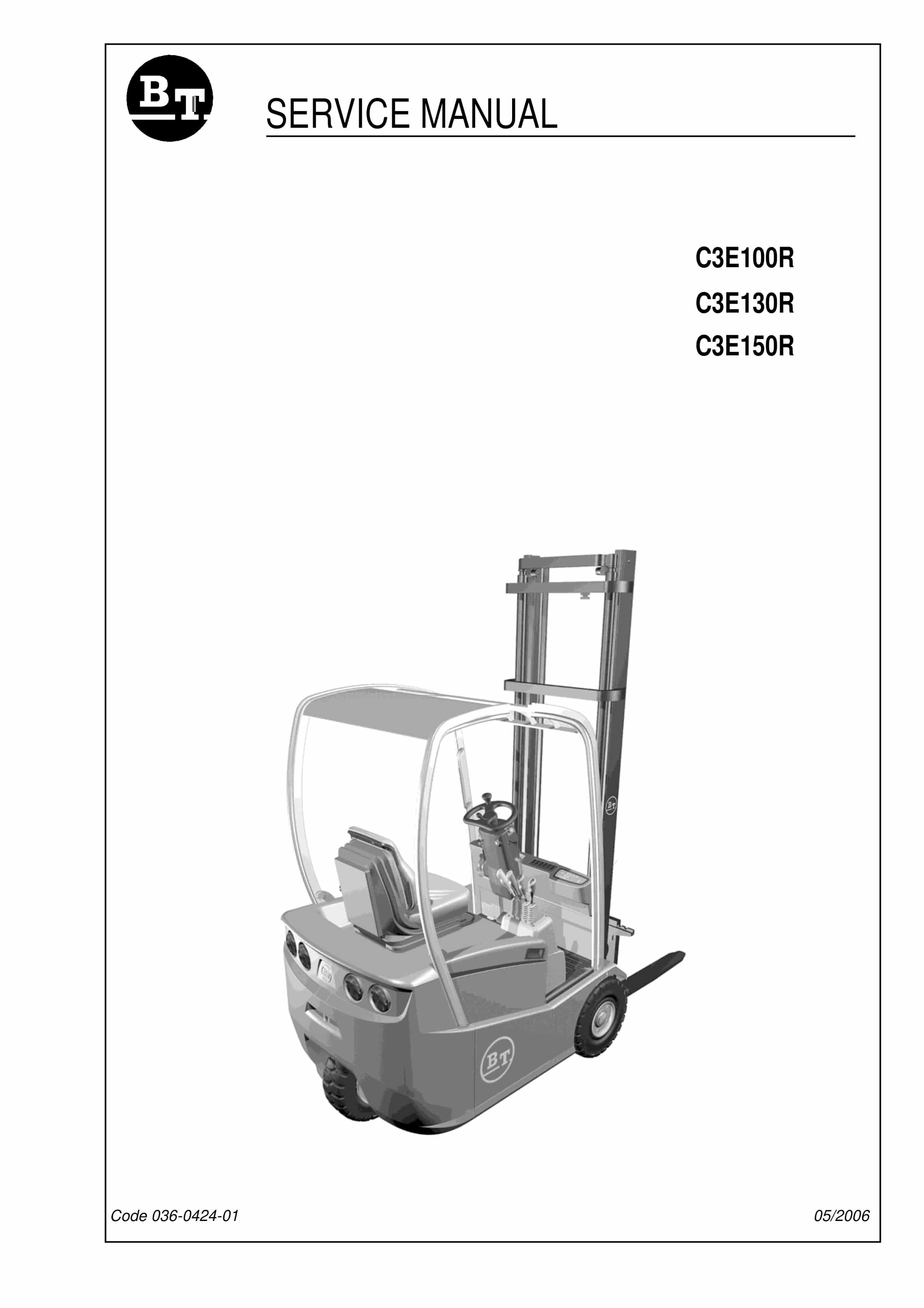
BT C3E130R, C3E150R, C3E100R Service Manual 036-0424-01
$30.00 Add to cart -
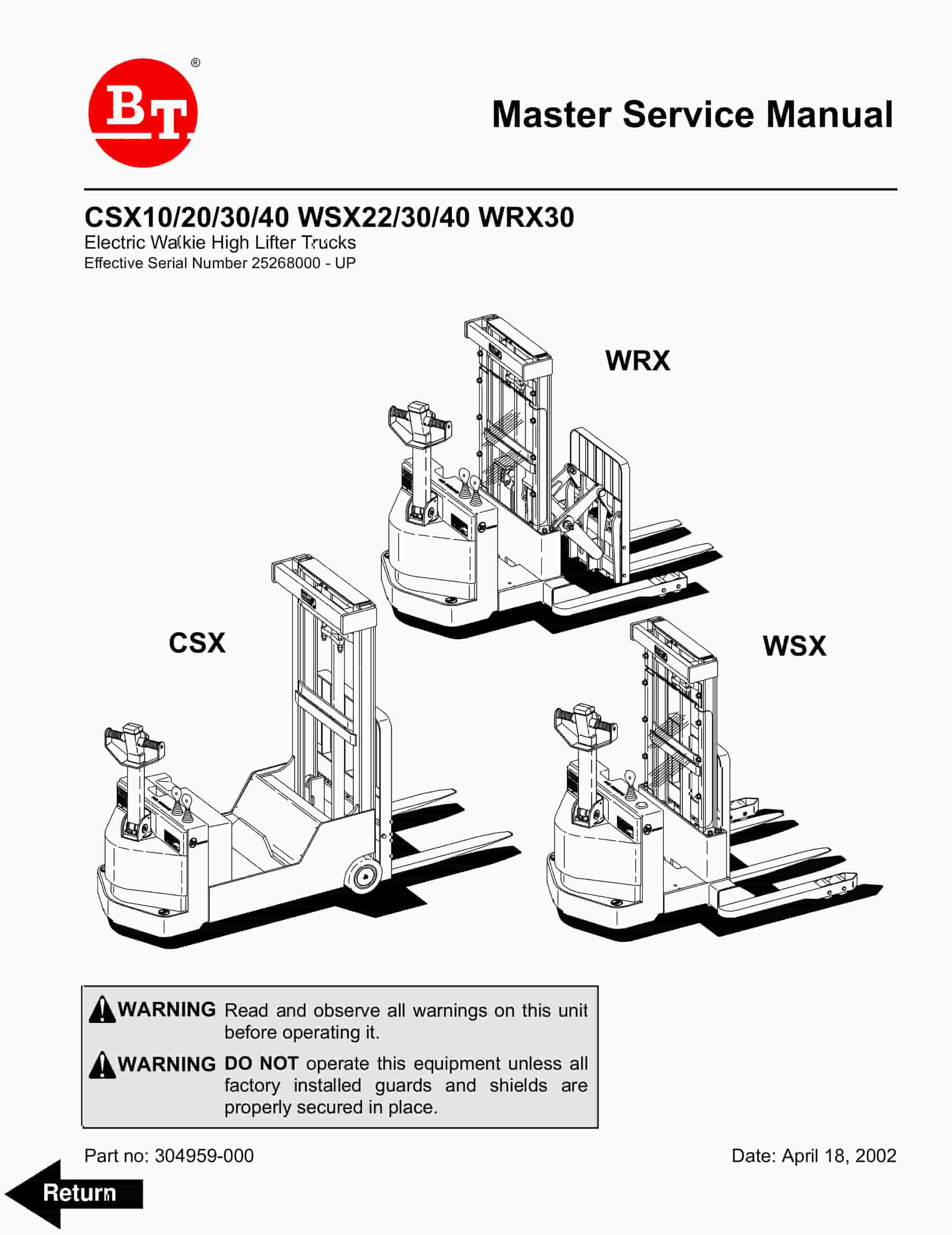
BT CSX10, CSX20, CSX30, CSX40, WSX22, WSX30, WSX40, WRX30 Electric Walkie High Lifter Truck Service Manual 304959-000
$30.00 Add to cart -
BT CBE 12T to CBE 20F Service Manual 036-0410-06
$30.00 Add to cart