No products in the cart.
Return to shop
$39.00
Linkbelt
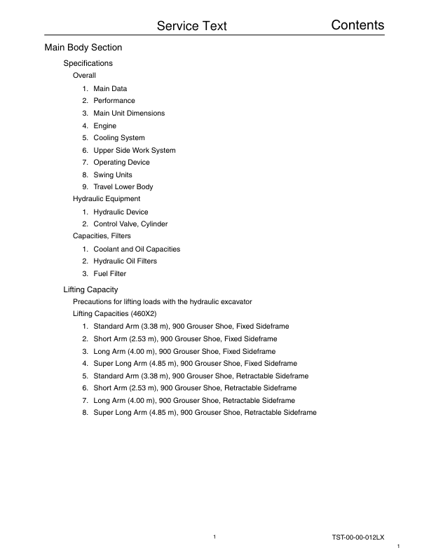
Linkbelt 460X2 Excavator Service Repair Manual
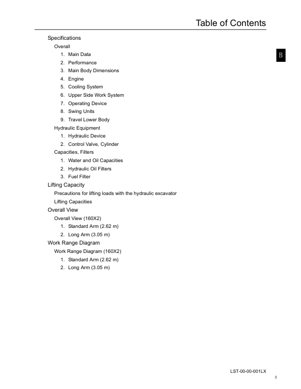
Linkbelt 160X2 Excavator Service Repair Manual
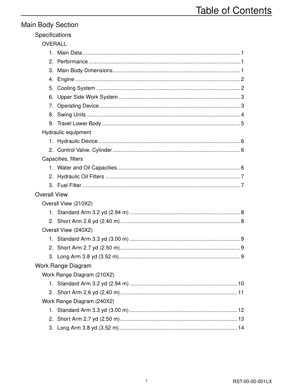
Linkbelt 210X2 Excavator Service Repair Manual
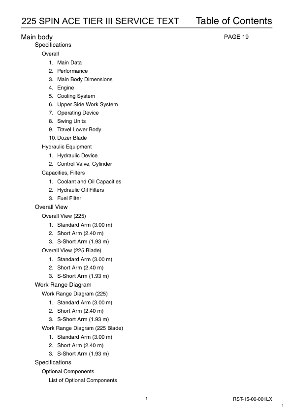
Linkbelt 225 Tier 3 Spin Ace Excavator Service Repair Manual
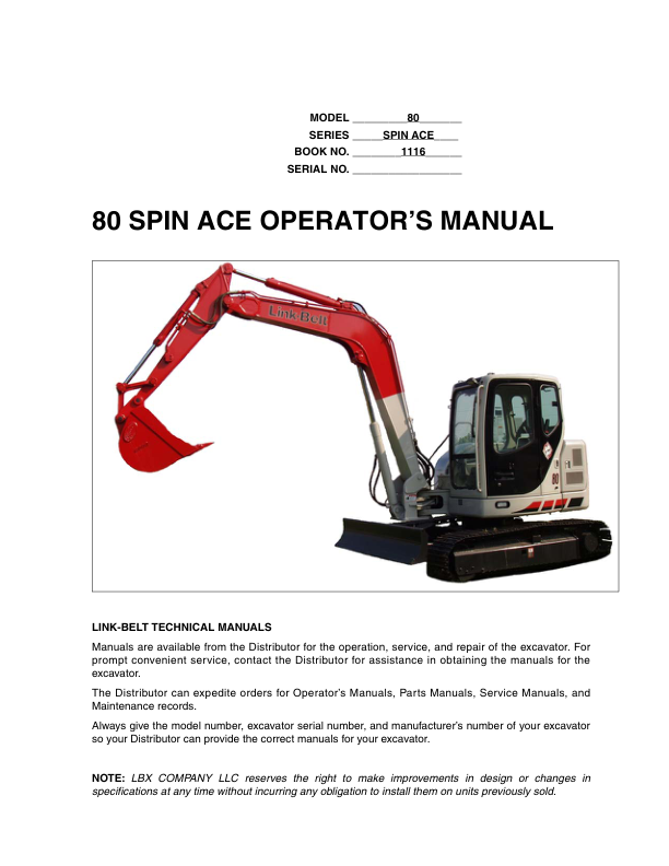
Linkbelt 80 Spin Ace Excavator Service Repair Manual
Linkbelt 700X2 Excavator Service Repair Manual
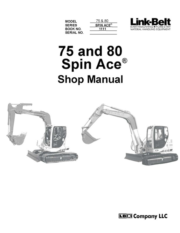
Linkbelt 75 Spin Ace Excavator Service Repair Manual
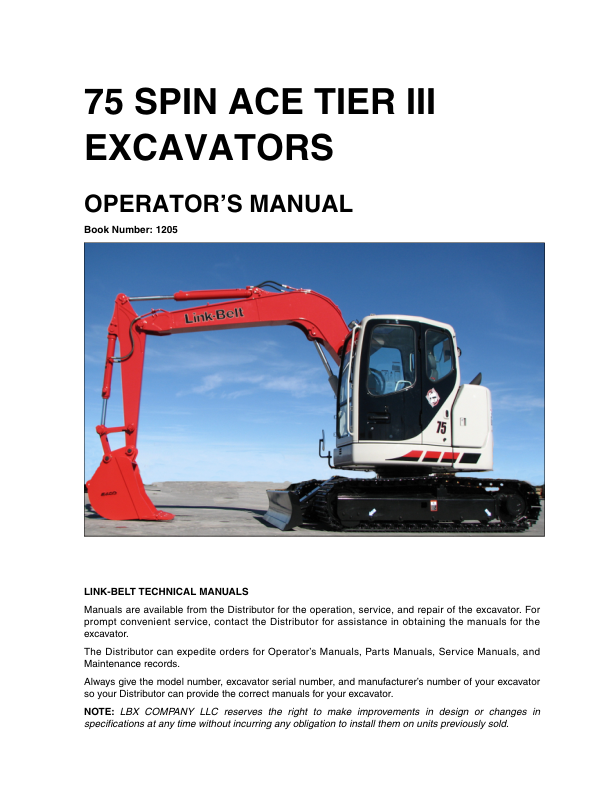
Linkbelt 75 Tier 3 Spin Ace Excavator Service Repair Manual
Linkbelt 240X2 Excavator Service Repair Manual
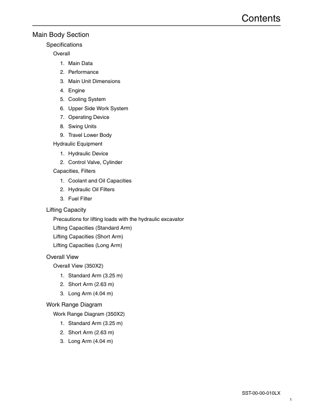
Linkbelt 350X2 Excavator Service Repair Manual


