


Caterpillar Service Manual PDF
Caterpillar 1204E Diesel Engine Service Manual SCEEA-AT15E-200
Caterpillar Service Manual PDF
Caterpillar 1204F Diesel Engine Disassembly and Assembly Service Manual 99799-67102
Caterpillar Service Manual PDF
Caterpillar 1204E Diesel Engine Specifications Service Manual 99799-64101

Caterpillar Service Manual PDF
Caterpillar 2EC15 to 2EC30 MicroCommand II Control Service Manual SENB8609
Caterpillar Service Manual PDF
Caterpillar 5V15D to 5V35D Mast Supplement Service Manual 99739-351S0
Caterpillar Service Manual PDF
Caterpillar 5M15D to 5M35D Mast Supplement Service Manual 99739-351T0
Caterpillar Service Manual PDF
Caterpillar 2EC15-30 Chassis and Mast Service Manual 99759-80100
Caterpillar Service Manual PDF
Caterpillar 4G63, 4G64 Fuel System Supplement Service Manual 99729-85110
Caterpillar Service Manual PDF
Caterpillar 4G63, 4G64 Gasoline Engine Service Manual 99729-84120
%20Gasoline%20Engine%20Service%20Manual%20SENB8525&url=https://ownersmanualpdf.net/docs/caterpillar-1-4-liter-4g33-gasoline-engine-service-manual-senb8525/&media=https://ownersmanualpdf.net/wp-content/uploads/2025/10/caterpillar-14-liter-4g33-gasoline-engine-service-manual-senb8525-1.jpg)
Caterpillar Service Manual PDF
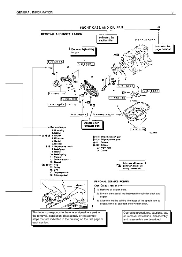
Caterpillar 1.4 Liter (4G33) Gasoline Engine Service Manual SENB8525