


Mitsubishi FG15N-35CN, FD20N-35N Chassis and Mast Service Manual 99719-M9140 Vol 1
$50.00
- Type Of Manual: Service Manual
- Manual ID: 99719-M9140 Vol 1
- Number of Pages: 631
- Size: 36.7MB
- Format: PDF
Category: Mitsubishi Service Manual PDF
-
Model List:
- FG15N, FG18N, FG20CN, FG20N, FG25N, FG28N, FG30N, FG33N, FG35CN, FD20N, FD25N, FD28N, FD30N, FD33N, FD35N
- 1. M9140_VOL1_FG15N_SERVICE_2014-07E1_MIT_50949
- 2. M9140_VOL2_FG15N_SERVICE_2014-07E1_MIT_50950
- 3. M9140_VOL3_FG15N_SERVICE_2014-07E1_MIT_50951
- 3.1. FOREWORD
- 3.1.1. Safety
- 3.1.2. Symbols and Abbreviations
- 3.1.3. Units
- 3.2. TABLE OF CONTENTS
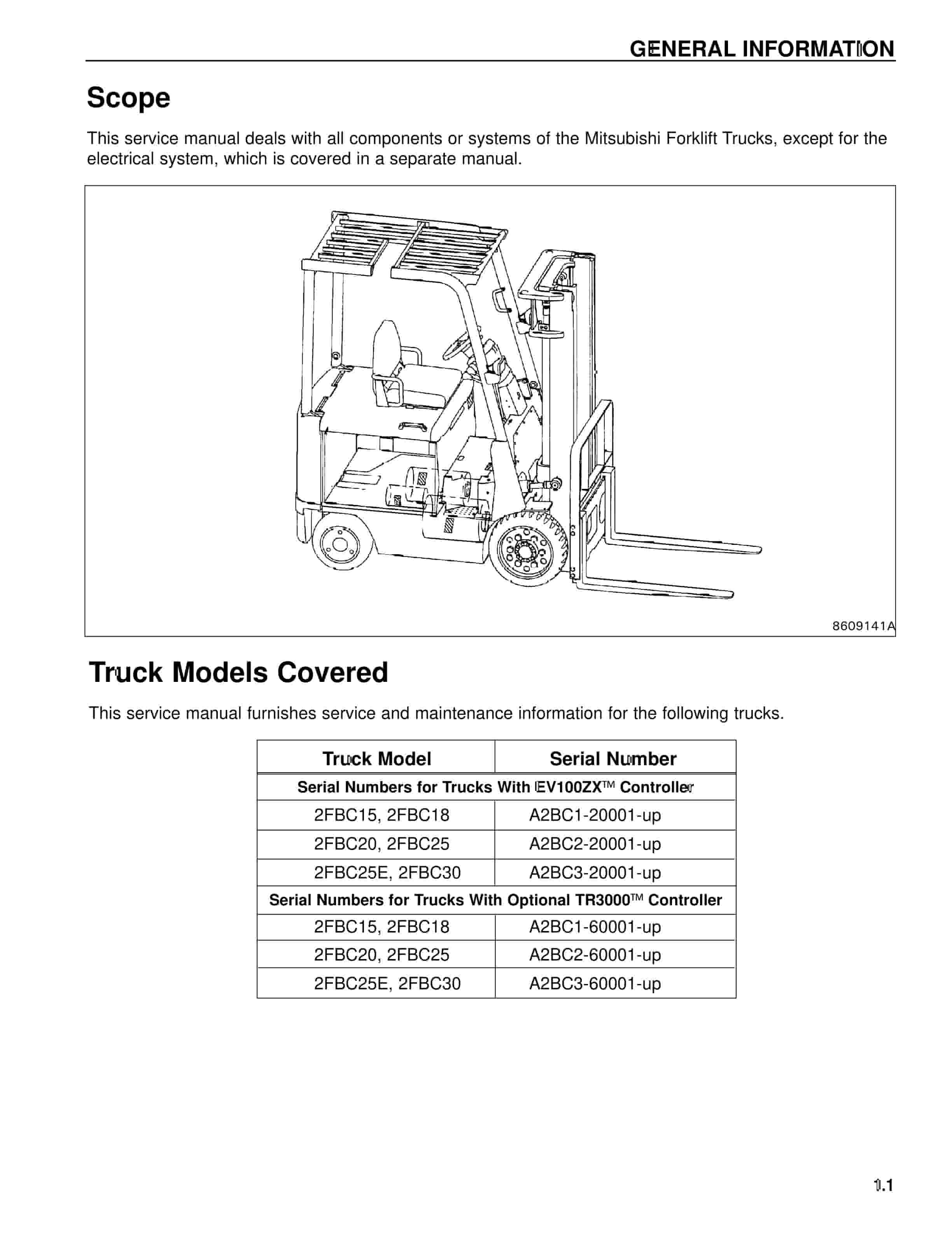
- 3.3. Chapter 1 GENERAL INFORMATION
- 3.3.1. Model View
- 3.3.2. Truck Models Covered
- 3.3.3. Serial Number Locations
- 3.3.4. Dimensions
- 3.3.5. Technical Data
- 3.4. Chapter 2 COOLING SYSTEM
- 3.4.1. Specification
- 3.4.2. Structure
- 3.4.3. Removing Fan Belt
- 3.4.3.1. Preparation
- 3.4.3.2. Removal Sequence
- 3.4.3.3. Suggestions for Removal
- 3.4.4. Installing Fan Belt
- 3.4.5. Inspecting and Adjusting Cooling System
- 3.4.5.1. Inspecting Fan Belt
- 3.4.5.2. Adjusting Fan Belt Tension
- 3.4.5.3. Connecting Radiator Hoses
- 3.4.5.4. Coolant
- 3.4.5.5. Radiator Cap
- 3.5. Chapter 3 ELECTRICAL SYSTEM
- 3.5.1. Electrical Components and Wiring Outline
- 3.5.1.1. Locations of Electrical Components
- 3.5.2. Console Box
- 3.5.2.1. Console Box Outline
- 3.5.2.2. Disassembling Console Box
- 3.5.2.3. Assembling Console Box
- 3.5.3. Meter Panel
- 3.5.3.1. Disassembling Meter Panel
- 3.5.3.2. Assembling Meter Panel
- 3.5.3.3. Bulb Replacement
- 3.5.4. Main Electrical Components
- 3.5.4.1. Meter Panel
- 3.5.4.2. Key Switch
- 3.5.4.3. Key Switch (Anti-Restart Switch)
- 3.5.4.4. Light Switch and Turn Signal Switch
- 3.5.4.5. Direction (FNR) Switch
- 3.5.4.6. Select Switch
- 3.5.4.7. Horn
- 3.5.4.8. Tank Unit
- 3.5.4.9. Brake Oil Sensor
- 3.5.4.10. Stop Light Switch
- 3.5.4.11. Thermoswitch (Engine Coolant Temperature)
- 3.5.4.12. Thermoswitch (T/C Oil)
- 3.5.4.13. Speed Sensor (Pulse Generator)
- 3.5.4.14. Parking Brake Switch
- 3.5.4.15. Relay Box
- 3.5.4.16. Fuse Box
- 3.5.4.17. QGS Controller (Diesel Model)
- 3.5.4.18. Rear Combination Light
- 3.5.4.19. Rear Combination Harness
- 3.5.4.20. List of Lights
- 3.5.5. Battery and Maintenance
- 3.5.5.1. State of Charge and Electrolyte Specific Gravity (S.G.) Adjustment
- 3.5.5.2. Specific Gravity Reading and State of Charge
- 3.5.5.3. Precautions for Battery Charging
- 3.5.6. Wire Color
- 3.5.6.1. List of Wire Color Codes
- 3.5.7. Troubleshooting
- 3.5.7.1. Starter System
- 3.5.7.2. Gauges
- 3.5.7.3. Lighting System
- 3.5.7.4. Alarm Unit
- 3.5.7.5. Battery
- 3.5.7.6. Horn Testing Procedures
- 3.5.8. Fuel Pressure Sensor Harness
- 3.5.8.1. Wire Harness
- 3.5.8.2. Converting the Year 2005/2006 Chassis Harness to 2004 Chassis Harness
- 3.5.8.3. Year 2005/2006 RELATIVE Fuel Pressure Sensor
- 3.5.8.4. Terminal Positions
- 3.5.8.5. Change the Wire Positions
- 3.5.8.6. Fuel Pressure Sensor Connector Kit P/N 91A04-06960
- 3.5.8.7. Change Pins
- 3.5.9. Wiring Harness Service Parts
- 3.5.9.1. Pick Tool Part
- 3.5.9.2. ETC Connector Assembly Part No. SE000218
- 3.5.9.3. ETC Pin Terminal W/ 6 Lead Part No. SE000219
- 3.5.9.4. Ignition Coil Connector Part No. 91A04-06590
- 3.5.9.5. Water Temp Sensor Connector Part No. 91A04-06410
- 3.5.9.6. Alternator Connector Part No. 91A04-06420
- 3.5.9.7. Air Flow Meter Connector Part No. 91A04-06580
- 3.5.9.8. LP Injector Driver Connector Part No. 05110-81230
- 3.5.9.9. Fuel Pressure Jumper Harness Part No. 91820-03200
- 3.5.9.10. Gasoline Injector Connector Part No. 91820-01840
- 3.5.9.11. Fuel Pressure Connector Part No. 91820-01850
- 3.5.9.12. Fuel Pressure Connector Part No. 91A04-06960
- 3.5.9.13. GSE Connector
- 3.5.9.14. Throttle Position Sensor
- 3.5.9.15. Soldering Procedure
- 3.5.9.16. Pin Removal Procedure
- 3.5.9.17. Pin Removal Procedure
- 3.5.10. Electrical Wiring Diagram
- 3.6. Chapter 4 CONTROLLER
- 3.6.1. Outline
- 3.6.2. Main Functions of Controllers
- 3.6.2.1. Meter Panel
- 3.6.2.2. VCM (Vehicle Control Module)
- 3.6.2.3. ECM (Engine Control Module)
- 3.6.2.4. GSE Connector
- 3.6.3. Service Tool
- 3.6.3.1. Service Tool Menus
- 3.6.3.2. Toolbox
- 3.6.3.3. Mot File Download Process
- 3.6.3.4. Check Main C Relay Circuit with Diagnostics Program
- 3.6.3.5. Programming Travel Speed
- 3.6.4. Mast Interlock System
- 3.6.4.1. Mast Interlock Function
- 3.6.4.2. Checking Procedure of Mast Interlock System
- 3.6.4.3. Active Test Inspection Procedure
- 3.6.5. Driving Interlock System
- 3.6.5.1. Controller Function
- 3.6.5.2. Checking the Operation of Driving Interlock Function
- 3.6.5.3. Active Test Inspection Procedure
- 3.6.6. Seat Belt Warning Light
- 3.6.6.1. Operation of Seat Belt Warning Light
- 3.6.6.2. Checking the Operation of Seat Belt Warning Light
- 3.6.7. Parking Brake Warning Buzzer and Light
- 3.6.7.1. Operation of Parking Brake Warning Buzzer and Light
- 3.6.7.2. Parking Brake Warning Buzzer
- 3.6.7.3. Checking the Operation of Parking Brake Warning Buzzer/Light with Key in OFF Position
- 3.6.8. Harness Codes
- 3.6.9. Controller Output Details
- 3.6.9.1. VCM (Vehicle Control Module)
- 3.6.9.2. Seat Switch
- 3.6.9.3. Parking Brake Switch
- 3.6.9.4. Direction Lever Switch
- 3.6.9.5. Vehicle Speed Sensor
- 3.6.9.6. T/M Solenoid
- 3.6.9.7. Unload Solenoid
- 3.6.9.8. Lift Lock Solenoid
- 3.6.9.9. Warning Buzzer
- 3.6.9.10. Warning Buzzer Relay
- 3.6.9.11. Warning Buzzer Circuit
- 3.6.9.12. Meter Panel
- 3.6.10. Truck Status Display and Troubleshooting
- 3.6.10.1. Truck Status Display
- 3.6.10.2. Diagnosis Table (F Code)
- 3.6.10.3. LED Blink Pattern
- 3.6.10.4. Diagnostic Codes and Troubleshooting
- 3.6.11. Common Diagnostic Codes
- 3.6.11.1. F85(T/M Forward Travel Solenoid Warning) and F87 (T/M Backward Travel Solenoid Warning) Displayed
- 3.6.11.2. E-23 (Throttle Sensor Warning)
- 3.6.11.3. E-24 (Accelerator Sensor Warning)
- 3.6.11.4. E-27 (POS Sensor Warning)
- 3.6.11.5. E-30 (ECCS C/U System Warning)
- 3.6.11.6. E-31 (Throttle Control Warning)
- 3.6.11.7. E-35 (LPG Fuel Injection Disconnection Warning)
- 3.6.11.8. E-38 (LPG Vaporizer Diagnostic Result Warning)
- 3.6.11.9. E-42 (Gas Air-Fuel Ratio Malfunction) and E-43 (LPG Air-Fuel Ratio MalFunction)
- 3.7. Chapter 5 POWER TRAIN
- 3.7.1. Removing and Installing Engine and Transmission Assembly (For Gasoline engine Trucks)
- 3.7.1.1. Removal Sequence of Overhead Guard, Covers, and Air Cleaner
- 3.7.1.2. Suggestions for Removal of Overhead Guard, Cover, and Air Cleaner
- 3.7.1.3. Removal Sequence of Controls
- 3.7.1.4. Suggestion for Removal of Controls
- 3.7.1.5. Installation Sequence of Overhead Guard, Covers, Air Cleaner, and Controls
- 3.7.1.6. Preparation for Removal of LPG System (Dual Fuel Gasoline and LPG Model)
- 3.7.1.7. Removal Sequence of LPG System (Dual Fuel Gasoline and LPG Model)
- 3.7.1.8. Installation Sequence of LPG System (Dual Fuel Gasoline and LPG Model)
- 3.7.1.9. Preparation for Removal of Radiator and Pipes
- 3.7.1.10. Removal Sequence of Radiator and Pipes
- 3.7.1.11. Suggestion for Removal of Radiator and Pipes
- 3.7.1.12. Installation Sequence of Radiator and Pipes
- 3.7.1.13. Preparation for Removal of Engine and Transmission Assembly
- 3.7.1.14. Removal Sequence of Engine and Transmission Assembly
- 3.7.1.15. Suggestions for Removal of Engine and Transmission Assembly
- 3.7.1.16. Installation Sequence of Engine and Transmission Assembly
- 3.7.1.17. Suggestions for Installation of Engine and Transmission Assembly
- 3.7.1.18. Removing and Installing of Engine and Transmission Assembly (For Diesel Engine Trucks)
- 3.7.1.19. Removal Sequence of Overhead Guard, Covers, and Air Cleaner
- 3.7.1.20. Suggestions for Removal of Overhead Guard, Covers, and Air Cleaner
- 3.7.1.21. Removal Sequence of Controls
- 3.7.1.22. Suggestions for Removal and Installation
- 3.7.1.23. Preparation for Removal of Radiator and Pipes
- 3.7.1.24. Removal Sequence of Radiator and Pipes
- 3.7.1.25. Suggestion for Removal of Radiator and Pipes
- 3.7.1.26. Installation Sequence of Radiator and Pipes
- 3.7.1.27. Preparation for Removal of Engine and Transmission Assembly
- 3.7.1.28. Removal Sequence of Engine and Transmission Assembly
- 3.7.1.29. Suggestions for Removal of Engine and Transmission Assembly
- 3.7.1.30. Installation of Engine and Transmission Assembly
- 3.7.1.31. Suggestion for Installation of Engine and Transmission Assembly (Those Not Shared with Gasoline Engine Trucks)
- 3.8. Chapter 6 POWERSHIFT TRANSMISSION
- 3.8.1. Structure
- 3.8.1.1. External View of Torque Converter Transmission
- 3.8.1.2. External View of Control Valve
- 3.8.1.3. Transmission Components
- 3.8.1.4. Torque Converter Components
- 3.8.1.5. Torque Converter Drive Control Components
- 3.8.1.6. Schematic Diagram of Powershift Transmission Hydraulic System
- 3.8.2. Removing Transmission
- 3.8.2.1. Suggestions for Removal
- 3.8.3. Installing Transmission
- 3.8.3.1. Suggestions for Installation
- 3.8.4. Disassembling Torque Converter Transmission
- 3.8.4.1. Preparation
- 3.8.4.2. Removing Transmission Accessories
- 3.8.4.3. Removing Oil Pump
- 3.8.4.4. Removing Transmission Housing
- 3.8.4.5. Removing Input Shaft, Idler Shaft and Output Gear
- 3.8.4.6. Disassembling Transmission Housing
- 3.8.4.7. Disassembling Torque Converter Housing
- 3.8.4.8. Disassembling Idler Shaft
- 3.8.4.9. Disassembling Output Gear
- 3.8.4.10. Disassembling Forward Side Input Shaft Gear Assembly
- 3.8.4.11. Disassembling Reverse Side Input Shaft Gear
- 3.8.4.12. Disassembling Oil Pump
- 3.8.5. Assembling Torque Converter Transmission
- 3.8.5.1. Assembling Transmission Housing
- 3.8.5.2. Assembling Idler Shaft Assembly
- 3.8.5.3. Assembling Output Gear Assembly
- 3.8.5.4. Inspecting Input Shaft Gear Assembly
- 3.8.5.5. Assembling Forward Side Input Shaft Gear Assembly
- 3.8.5.6. Assembling Reverse Side Input Shaft Gear Assembly
- 3.8.5.7. Assembling and Installing Oil Pump Assembly
- 3.8.5.8. Assembling Torque Converter Housing
- 3.8.5.9. Installing Transmission Housing
- 3.8.5.10. Installing Servo Case Assembly
- 3.8.5.11. Installing Transmission Accessories
- 3.8.6. Disassembling Control Valve
- 3.8.6.1. Removing Control Valve Accessories
- 3.8.6.2. Removing Valve Body Plate
- 3.8.6.3. Removing Plugs
- 3.8.6.4. Removing Strainer
- 3.8.6.5. Disassembling Regulator Valve Section
- 3.8.6.6. Disassembling Accumulator Valve Section
- 3.8.6.7. Disassembling Inching Valve Section
- 3.8.6.8. Removing Oil Seal and Plug
- 3.8.7. Assembling Control Valve
- 3.8.7.1. Assembly Sequence of Control Valve
- 3.8.7.2. Suggestions for Assembly
- 3.8.7.3. Washing and Inspecting
- 3.8.7.4. Installing Valve Plug and Oil Seal
- 3.8.7.5. Assembling Inching Valve Section
- 3.8.7.6. Assembling Accumulator Valve Section
- 3.8.7.7. Assembling Regulator Valve Section
- 3.8.7.8. Installing Strainer
- 3.8.7.9. Installing Plug
- 3.8.7.10. Installing Valve Body Plate and Breather Cover
- 3.8.7.11. Assembling Control Valve Accessories
- 3.8.8. Inspection and Adjustment
- 3.8.8.1. Oil Pressure Measurement
- 3.8.8.2. Adjusting Brake (Inching) Pedal
- 3.8.8.3. Adjusting Inching Cable
- 3.8.8.4. Increasing the Inching Pedal Return Spring Tension
- 3.8.9. Troubleshooting
- 3.8.10. Service Data
- 3.8.10.1. Pump Boss
- 3.8.10.2. Pilot Boss
- 3.8.10.3. Oil Pump
- 3.8.10.4. Flexible Plate
- 3.8.10.5. Clutches
- 3.8.10.6. Input Shaft
- 3.9. Chapter 7 FRONT AXLE AND REDUCTION DIFFERENTIAL
- 3.9.1. Structure
- 3.9.1.1. Ton Class
- 3.9.1.2. Ton Class
- 3.9.1.3. Ton Class
- 3.9.2. Removing Front Wheels
- 3.9.2.1. Preparation
- 3.9.2.2. Removal
- 3.9.2.3. Suggestion for Removal
- 3.9.3. Installing Front Wheels
- 3.9.4. Removing Front Axle and Reduction Differential
- 3.9.4.1. Preparation
- 3.9.4.2. Removal Sequence
- 3.9.4.3. Suggestions for Removal
- 3.9.5. Installing Front Axle
- 3.9.6. Disassembling Front Axle
- 3.9.6.1. Disassembly Sequence
- 3.9.6.2. Suggestions for Disassembly
- 3.9.7. Inspection and Repair After Disassembling Front Axle
- 3.9.8. Assembling Front Axle
- 3.9.9. Disassembling Reduction Differential
- 3.9.9.1. Disassembly Sequence
- 3.9.9.2. Suggestions for Disassembly
- 3.9.10. Inspection and Repair After Disassembling Reduction Differential
- 3.9.11. Assembling Reduction Differential
- 3.9.11.1. Assembly Sequence
- 3.9.11.2. Suggestions for Assembly
- 3.9.11.3. Adjustment
- 3.9.12. Troubleshooting
- 3.9.13. Service Data
- 3.9.13.1. Hub and Wheels
- 3.9.13.2. Reduction Differential
- 3.10. Chapter 8 REAR AXLE
- 3.10.1. Structure
- 3.10.1.1. Main Components of Rear Axle
- 3.10.1.2. Specifications for Wheel Alignment and Steering Angle
- 3.10.1.3. Main Components of Wheel Hub
- 3.10.1.4. Main Components of King Pin
- 3.10.1.5. Main Components of Tie Rod
- 3.10.1.6. Main Components of Steering Cylinder
- 3.10.2. Removing Rear Wheels
- 3.10.3. Installing Rear Wheels
- 3.10.4. Removing Rear Wheels and Rear Axle Assembly
- 3.10.4.1. Removal Sequence
- 3.10.4.2. Suggestions for Removal
- 3.10.5. Installing Rear Wheels
- 3.10.6. Disassembling Wheel Hub
- 3.10.6.1. Disassembly Sequence
- 3.10.6.2. Suggestions for Disassembly
- 3.10.7. Inspection and Repair After Disassembly
Rate this product
You may also like
Mitsubishi Service Manual PDF
$50.00
Mitsubishi Service Manual PDF
Mitsubishi 5V15D, 5V20D, 5V25D, 5V30D, 5V35D Mast Supplement Service Manual 99739-151S0
$50.00
Mitsubishi Service Manual PDF
Mitsubishi 1204E Diesel Engine Systems Operation Testing and Adjusting Service Manual 99799-56103
$50.00
Mitsubishi Service Manual PDF
Mitsubishi 4G63, 4G64 Fuel System Supplement Service Manual 99729-75110
$50.00
Mitsubishi Service Manual PDF
$50.00
Mitsubishi Service Manual PDF
$50.00
Mitsubishi Service Manual PDF
$50.00
Mitsubishi Service Manual PDF
Mitsubishi 4G63, 4G64 Gasoline Engine Service Manual 99729-14110
$50.00
Mitsubishi Service Manual PDF
$50.00