

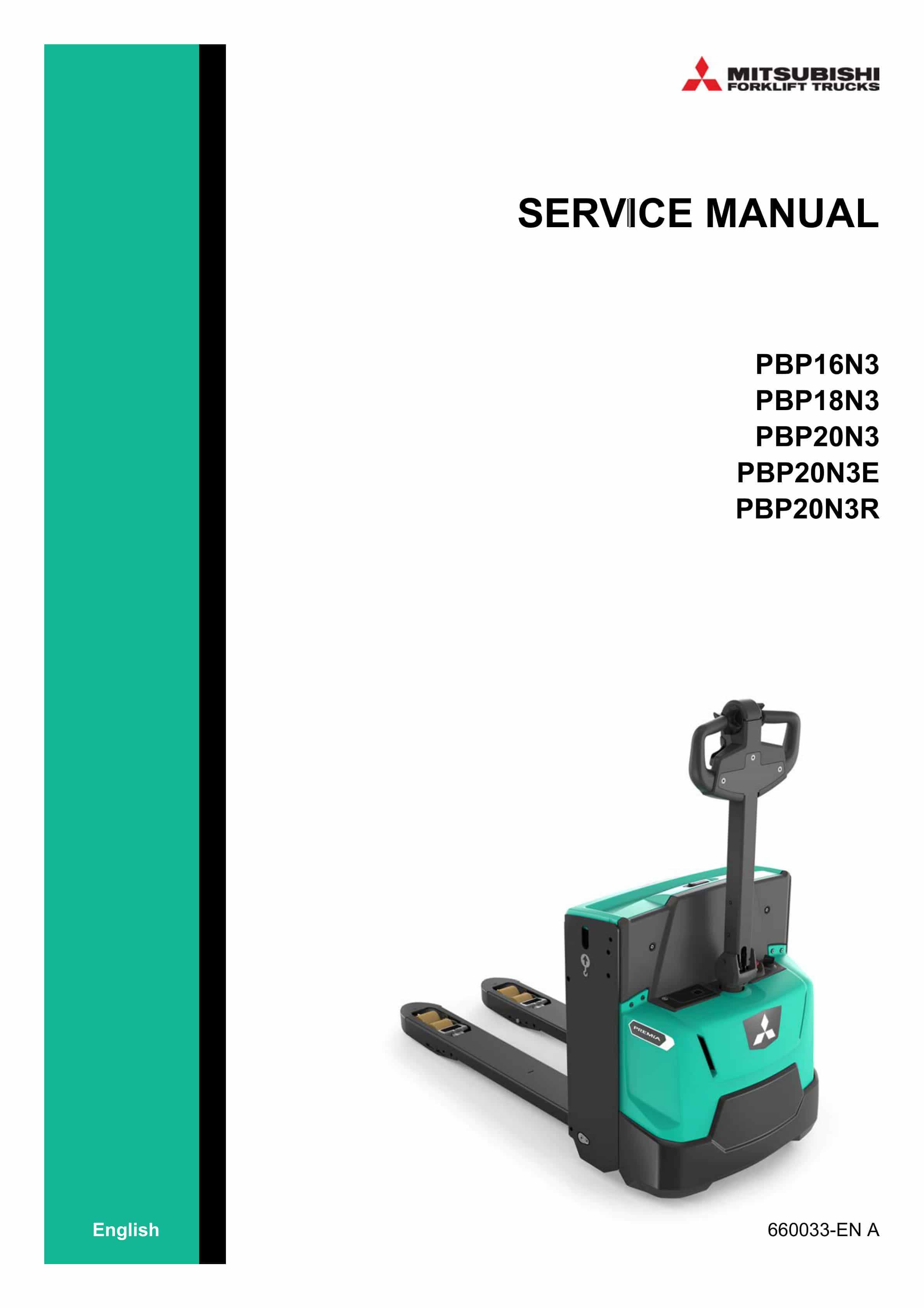
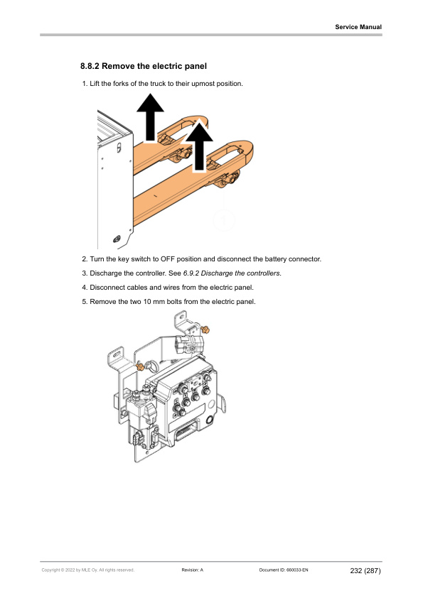
Mitsubishi PBP16N3, PBP18N3, PBP20N3, PBP20N3E, PBP20N3R Service Manual 660033 EN-A
$50.00
- Type Of Manual: Service Manual
- Manual ID: 660033
- Language: EN-A
- Number of Pages: 289
- Size: 10.7MB
- Format: PDF
Product details
-
Model List:
- PBP16N3, PBP18N3, PBP20N3, PBP20N3E, PBP20N3R
- 1. Table of contents
- 2. Foreword
- 3. How to read this manual
- 3.1. Safety-related signs
- 3.2. Safety symbols
- 3.3. Units
- 3.4. Interactive links
- 4. Safety instructions
- 4.1. General safety instructions
- 4.2. Safety requirements for industrial trucks
- 4.3. Repairs and structural modifications
- 4.4. Instructions for site supervision
- 4.5. Service area safety
- 4.6. Occupational safety
- 4.7. Personal safety
- 4.8. Work safety
- 4.9. Operating temperature
- 5. General information
- 5.1. Truck models covered by this manual
- 5.2. Transportation
- 5.2.1. Lifting the truck
- 5.2.1.1. Jack points
- 5.2.1.2. Hoist points
- 5.2.2. Towing the truck
- 5.2.3. Brake release
- 5.3. Operating position
- 5.4. Operating direction
- 5.5. Special tools
- 5.6. Assembly and commissioning
- 5.7. Order spare parts
- 6. Main components
- 6.1. Identification plates and stickers
- 6.2. Operating devices
- 6.3. Tiller arm
- 6.3.1. Tiller arm controls
- 6.3.2. Tiller arm positions
- 6.4. Truck covers
- 6.5. Battery compartment
- 6.6. Control panel
- 6.6.1. Emergency stop button
- 6.6.2. Key switch
- 6.6.3. Multi-functional display
- 6.7. Foldable operator platform
- 6.8. Load handling
- 6.8.1. Hydraulic cylinders
- 6.9. Electric system
- 6.9.1. Electrical operation
- 6.9.1.1. Overview
- 6.9.1.2. How to use the schematic diagram
- 6.9.1.3. Power source
- 6.9.1.4. Safety circuit (emergency stop button)
- 6.9.1.5. Key switch
- 6.9.1.6. Traction
- 6.9.1.7. AC motor operation
- 6.9.2. Traction and pump controller
- 6.9.2.1. Traction and pump controller connectors
- 6.9.2.2. CNA external connector
- 6.9.2.3. Description of the power connections
- 6.9.3. Horn
- 6.9.4. Sensors
- 6.9.5. Fuses
- 6.9.6. Relays and contactors
- 6.9.7. Display connector
- 6.10. Hydraulic operation
- 6.10.1. Hydraulic aggregate
- 6.10.1.1. Pump motor
- 6.10.2. Hydraulic symbols
- 6.10.3. Hydraulic operation overview
- 6.10.4. Hydraulic operation lifting/lowering
- 6.10.5. Additional hydraulic functions with lifting forks
- 6.11. Drive unit
- 6.11.1. Traction motor
- 6.11.2. Magnetic brake
- 6.11.2.1. Service brake
- 6.11.2.2. Parking brake
- 6.11.2.3. Emergency braking
- 6.12. Wheels
- 6.13. Truck suspension
- 7. Maintenance
- 7.1. Safety instructions for maintenance
- 7.2. Maintenance intervals
- 7.3. Opening the covers
- 7.3.1. Remove the front cover
- 7.3.2. Remove the control panel
- 7.3.3. Remove the top cover
- 7.3.4. Open the battery cover
- 7.4. Drive unit
- 7.4.1. Transmission gear
- 7.4.1.1. Fastening of the transmission gear
- 7.4.1.2. Leakage check of the transmission gear
- 7.4.2. Slewing bearing
- 7.4.3. Magnetic brake
- 7.4.3.1. Measure the thickness of the brake disc
- 7.4.3.2. Measure the coil resistance
- 7.4.4. Drive unit suspension
- 7.4.4.1. Inspect the drive unit suspension
- 7.4.4.2. Lubricate the drive unit suspension
- 7.5. Hydraulics
- 7.5.1. Hydraulic system maintenance
- 7.5.2. Hydraulic filters
- 7.5.3. Solenoid valve functionality check
- 7.5.4. Leakage check of the hydraulic system
- 7.5.5. Hoses and cylinders
- 7.5.6. Hydraulic oil tank
- 7.5.6.1. Hydraulic oil change
- 7.5.6.2. Oil level
- 7.5.6.3. Clean the oil tank
- 7.6. Lifting system
- 7.6.1. Check the cylinders and piston rods
- 7.6.2. Lifting test
- 7.6.3. Fork inspection
- 7.6.4. Examine the load backrest for cracks
- 7.7. Lifting forks
- 7.7.1. Examine the welding in lifting carriage for cracks
- 7.7.2. Examine the rollers, pins and welds for cracking and damage
- 7.7.3. Lifting chains
- 7.7.3.1. Chain tension
- 7.7.3.2. Chain lubrication
- 7.7.3.3. Chain wear measurement
- 7.7.3.4. Check the chain anchors and locking pins
- 7.8. Wheels
- 7.8.1. Before you replace the wheels
- 7.8.2. Traction wheel
- 7.8.2.1. Remove the traction wheel
- 7.8.2.2. Replace the wheel shaft bolts
- 7.8.2.3. Install the traction wheel
- 7.8.3. Castor wheel
- 7.8.3.1. Replace the castor wheel
- 7.8.3.2. Adjust the castor wheel
- 7.8.3.3. Inspect the castor wheel suspension
- 7.8.4. Load wheels
- 7.8.4.1. Replace the load wheels
- 7.9. Electrics
- 7.9.1. Electrical connections tightening torques
- 7.9.2. Discharge the controllers
- 7.9.3. Contactor functionality check
- 7.9.4. Test the functionality of sensors
- 7.9.4.1. Traction motor sensors
- 7.9.4.2. Tiller arm sensor
- 7.9.4.3. Operator platform sensors
- 7.9.4.4. Battery cover sensor
- 7.9.4.5. Lifting fork limit sensor
- 7.9.4.6. Lifting forks down sensor
- 7.9.5. Test the functionality of switches and buttons
- 7.9.5.1. Emergency stop button
- 7.9.5.2. Key switch functionality check
- 7.9.5.3. Tiller arm control buttons
- 7.9.6. Test the functionality of the horn
- 7.9.6.1. Horn
- 7.9.6.2. Horn diode
- 7.9.7. Wiring harnesses and cables
- 7.9.8. Examine and clear the alarm history
- 7.9.9. Insulation resistance test
- 7.9.9.1. Test voltage
- 7.9.9.2. Check the insulation tester
- 7.9.9.3. Measure the insulation resistance
- 7.10. General
- 7.10.1. How to clean the truck
- 7.10.2. Lubrication
- 7.10.3. Examine the welding in the truck frame for cracking
- 7.10.4. Examine the truck frame and the lifting carriage
- 7.10.5. Examine the gas springs
- 7.10.6. Examine the condition and position of the identification plates
- 7.10.7. Examine the covers
- 7.10.8. Safety functions
- 8. Battery maintenance
- 8.1. Lead-acid batteries
- 8.1.1. Safety with lead-acid batteries
- 8.1.2. General information
- 8.1.3. Requirements for battery charging areas
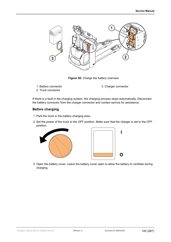
- 8.1.4. Charge the battery with the external charger
- 8.1.5. Charge the battery with the internal charger
- 8.1.6. Battery maintenance
- 8.1.6.1. General maintenance
- 8.1.6.2. How to clean the battery
- 8.1.6.3. Daily maintenance
- 8.1.6.4. Weekly maintenance
- 8.1.6.5. Monthly maintenance
- 8.1.6.6. Annual maintenance
- 8.1.7. Malfunctions
- 8.1.8. Acquire a new battery
- 8.1.9. Storage
- 8.2. Lithium-ion batteries
- 8.2.1. General information
- 8.2.2. Safety signs
- 8.2.3. Requirements for battery charging areas
- 8.2.4. Charge the battery
- 8.2.4.1. Recharging a lithium-ion battery
- 8.2.4.2. Charge the battery with the external charger
- 8.2.4.3. Charge the battery with the internal charger
- 8.2.4.4. Opportunity charging
- 8.2.4.5. Battery balancing
- 8.2.5. Battery maintenance
- 8.2.5.1. Examine the battery
- 8.2.5.2. How to clean the battery
- 8.2.5.3. Malfunctions
- 8.2.5.4. Service and repair
- 8.2.6. Acquire a new battery
- 8.2.7. Storage
- 8.3. Replace the battery
- 8.3.1. General safety instructions
- 8.3.2. Replace the battery with a lifting device
- 8.3.3. Replace the battery with a battery change device
- 8.4. Battery cover maintenance
- 8.4.1. Remove the rubber absorbers of the battery cover
- 8.4.2. Remove the battery cover lock
- 9. Repair
- 9.1. Repair drive unit
- 9.1.1. Remove the drive unit
- 9.1.2. Disassemble the drive unit
- 9.1.3. Measuring the run-out of the connecting face of the motor
- 9.1.4. Assemble the drive unit
- 9.2. Repair foldable operator platform
- 9.2.1. Remove the foldable operator platform
- 9.2.2. Replace the rubber absorbers of the foldable operator platform
- 9.2.3. Replace the gas springs of the platform
- 9.2.4. Replace the slide bearing of the platform
- 9.3. Repair tiller arm
- 9.3.1. Remove the steering assembly
- 9.3.2. Remove the tiller arm
- 9.3.3. Replace the gas spring of the tiller arm
- 9.3.4. Remove the tiller head
- 9.3.4.1. Replace the acceleration controllers
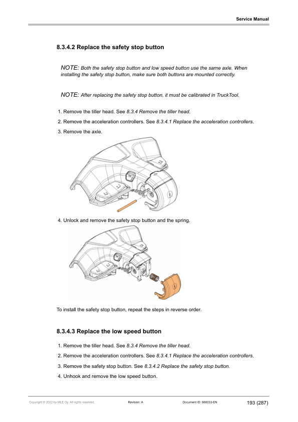
- 9.3.4.2. Replace the safety stop button
- 9.3.4.3. Replace the low speed button
- 9.3.4.4. Replace the tiller sensor box
- 9.3.4.5. Replace the lifting/lowering buttons
- 9.3.4.6. Replace the horn buttons
- 9.4. Repair hydraulic system
- 9.4.1. Disassemble the hydraulic aggregate
- 9.4.2. Set the lifting pressure
- 9.4.3. Disassemble the lifting fork valve
- 9.5. Repair lifting system
- 9.5.1. Disassemble the linkage mechanism
- 9.5.2. Remove the hydraulic cylinder
- 9.5.3. Replace the sealing housing of the hydraulic cylinder
- 9.5.4. Replace the slide bearings of the hydraulic cylinder
- 9.6. Repair lifting forks assembly
- 9.6.1. Disassemble the lifting fork carriage
- 9.6.2. Main rollers of the lifting fork carriage
- 9.6.2.1. Adjust the main rollers of the lifting fork carriage
- 9.6.2.2. Disassemble the main rollers of the lifting fork carriage
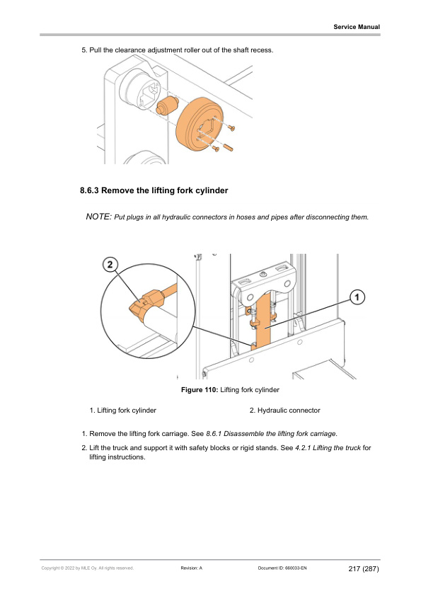
- 9.6.3. Remove the lifting fork cylinder
- 9.6.4. Replace the sealing housing of the lifting fork cylinder
- 9.6.5. Adjust the lifting chains
- 9.6.6. Replace the lifting chains
- 9.7. Repair truck suspension
- 9.7.1. Disassemble the castor wheel suspension
- 9.7.2. Disassemble the drive unit suspension
- 9.8. Repair electric system
- 9.8.1. Replace the fuses
- 9.8.2. Remove the electric panel
- 9.8.3. Replace the contactor
- 9.8.4. Replace the traction and pump controller
- 9.8.5. Replace the truck connector
- 9.8.6. Install the traction motor cables
- 9.8.7. Replace the horn
- 9.9. Repair sensors and switches
- 9.9.1. Replace the rotation sensor
- 9.9.2. Replace the tiller arm sensor
- 9.9.3. Replace the operator platform sensors
- 9.9.4. Replace the battery cover sensor
- 9.9.5. Replace the lifting fork limit sensor
- 9.9.6. Replace the lifting forks down sensor
- 10. TruckTool Diagnostics
- 10.1. Overview
- 10.2. Location of the service socket
- 10.3. Parameter descriptions
- 11. Service data
- 11.1. Special tightening torques
- 11.2. Tightening torques for standard bolts and nuts
- 11.3. Oils and lubricants
- 11.3.1. Channels of the lifting structure
- 11.3.2. Lifting chain
- 11.4. Troubleshooting
- 12. Options
- 12.1. Options overview
- 12.2. Load backrest
- 12.2.1. Install the load backrest
- 12.3. Pallet entry and exit rollers
- 12.3.1. Remove the pallet entry and exit rollers
- 12.4. Accessory rack
- 12.4.1. Install the accessory rack
- 12.4.2. Install the list bracket
- 12.4.3. Install the computer holder
- 12.4.4. Install the working light
- 12.5. Battery connector and cable
- 12.5.1. Replace battery connector and cable
- 12.6. Battery change device
- 12.7. Charger connector
- 12.7.1. Replace the charger connector
- 12.8. Internal charger and internal charger connector
- 12.8.1. Install the internal charger and charger connector
- 12.9. Voltage converter
- 12.9.1. Install the voltage converter
- 12.10. PIN code unit keyboard
- 12.10.1. Install the PIN code unit
- 12.10.2. Activate the truck with a PIN code
- 13. Technical specifications
- 13.1. Dimensions
- 13.2. Technical data
- 14. Declaration of Conformity
- 15. Stickers
- 16. Maintenance check list
- 17. Notes
Related products
-
Mitsubishi 4DQ7, S4S Diesel Engine Service Manual
$50.00 Add to cart -
Mitsubishi 4DQ5, S4E, S4E2 Diesel Engine Service Manual
$50.00 Add to cart -
Mitsubishi 4G63, 4G64 Gasoline Engine Service Manual 99729-74120
$50.00 Add to cart -
Mitsubishi 1204E Diesel Engine Disassembly and Assembly Service Manual 99799-56102
$50.00 Add to cart -
Mitsubishi GM 4.3L (G6) Fuel System Supplement Service Manual 99789-74111
$50.00 Add to cart


%20Fuel%20System%20Supplement%20Service%20Manual%2099789-74111&url=https://ownersmanualpdf.net/docs/mitsubishi-gm-4-3l-g6-fuel-system-supplement-service-manual-99789-74111/&media=https://ownersmanualpdf.net/wp-content/uploads/2025/10/mitsubishi-gm-43l-g6-fuel-system-supplement-service-manual-99789-74111-1.jpg)