No products in the cart.
Return to shop
$30.00
Caterpillar Parts Manual PDF
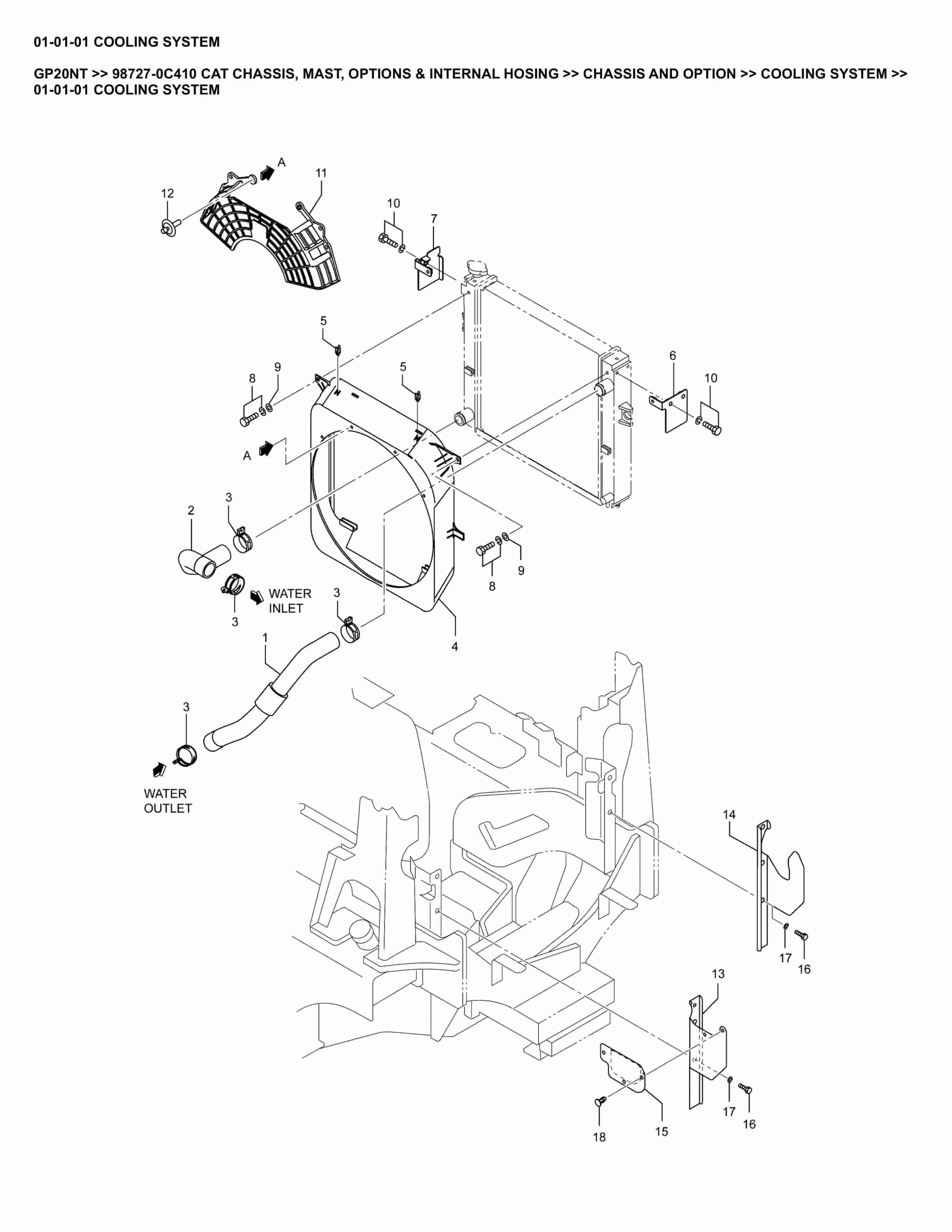
Caterpillar GP20NT Parts Manual 98727-0C410
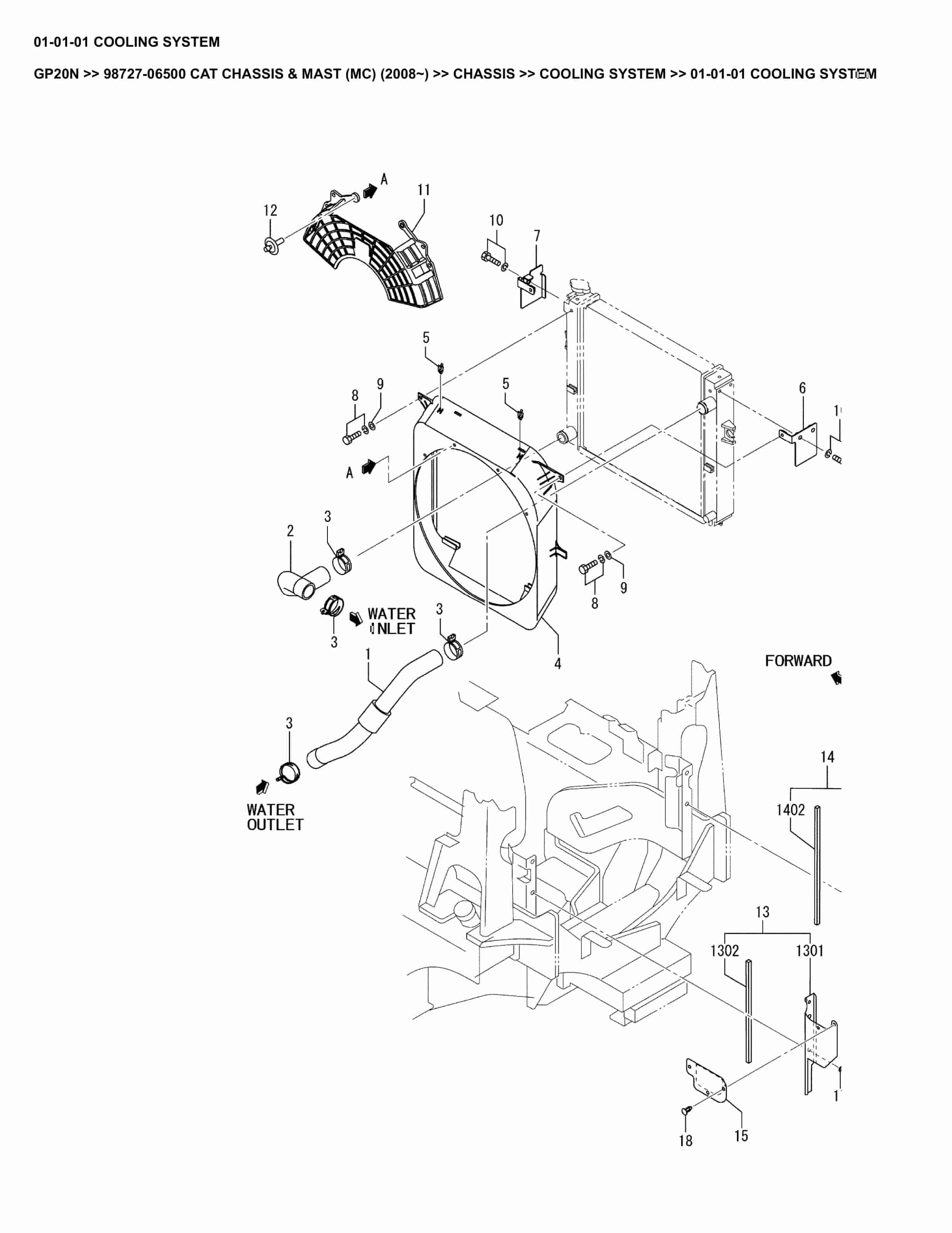
Caterpillar GP20N Parts Manual 98727-06500
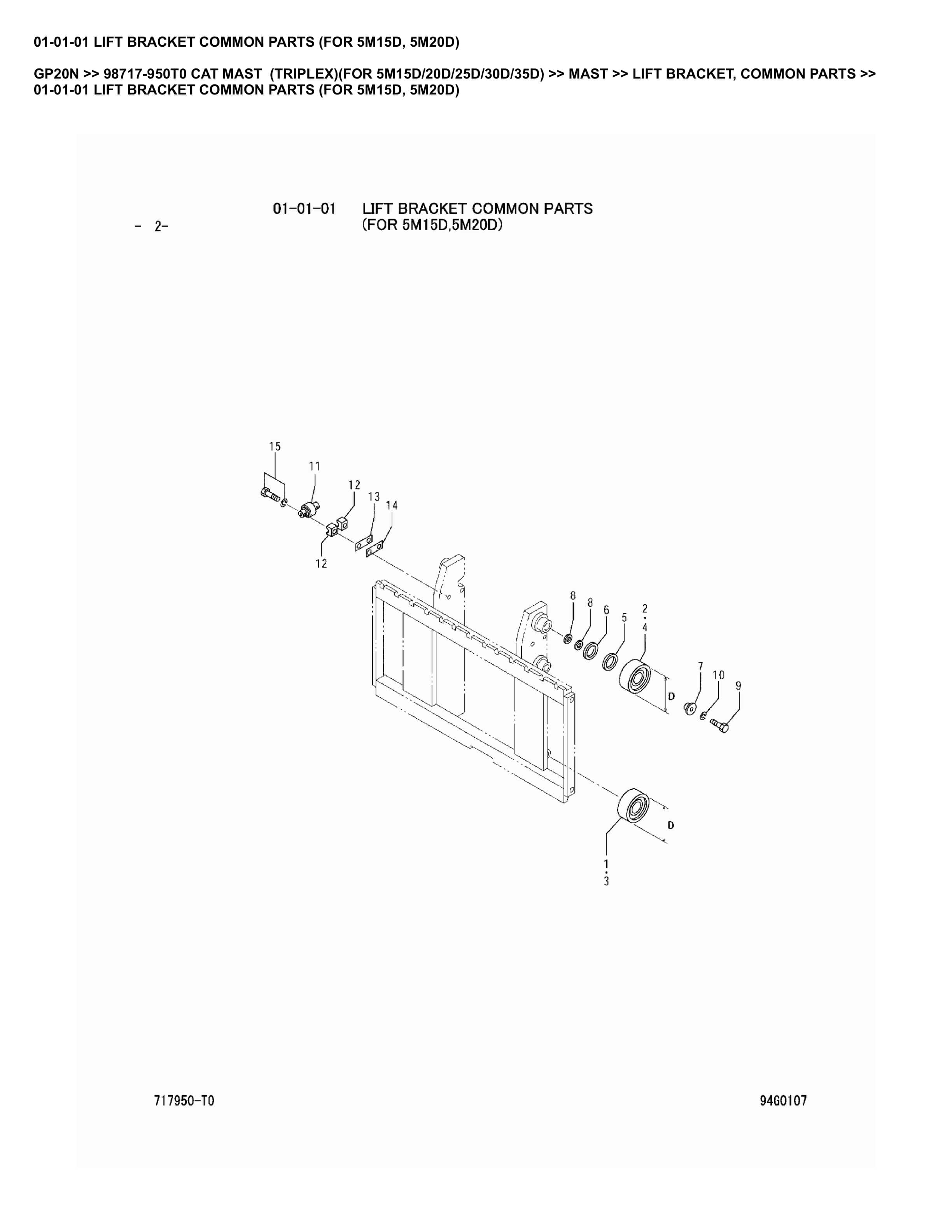
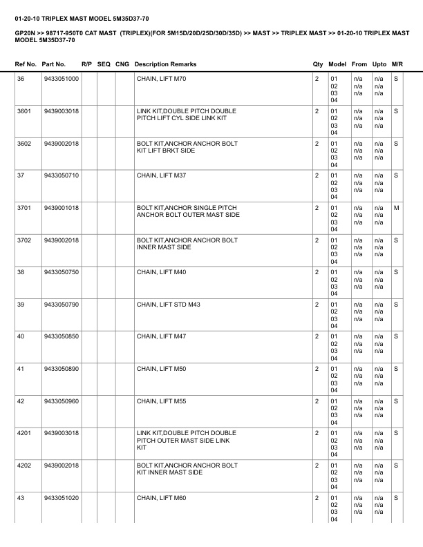
Caterpillar GP20N Parts Manual 98717-950T0
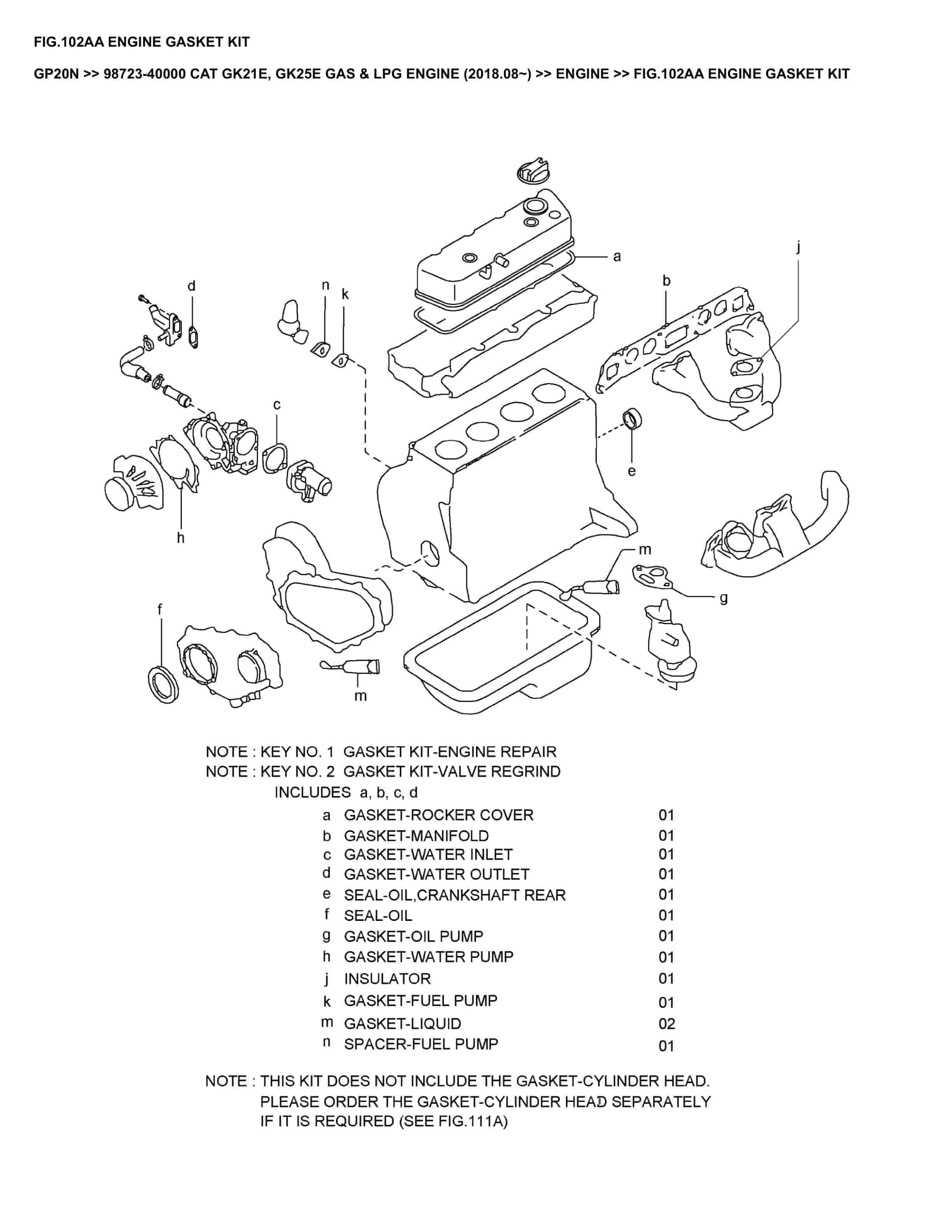
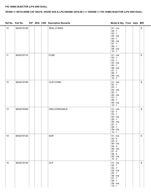
Caterpillar GP20N Parts Manual 98723-40000
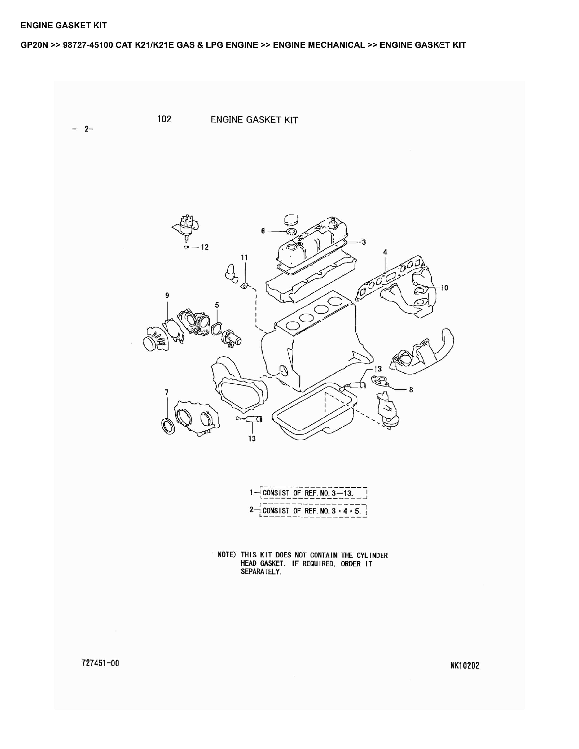
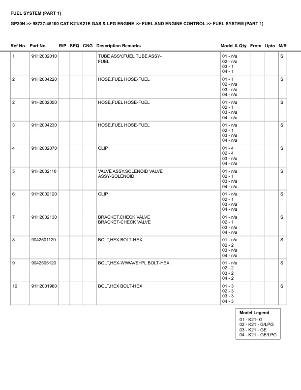
Caterpillar GP20N Parts Manual 98727-45100
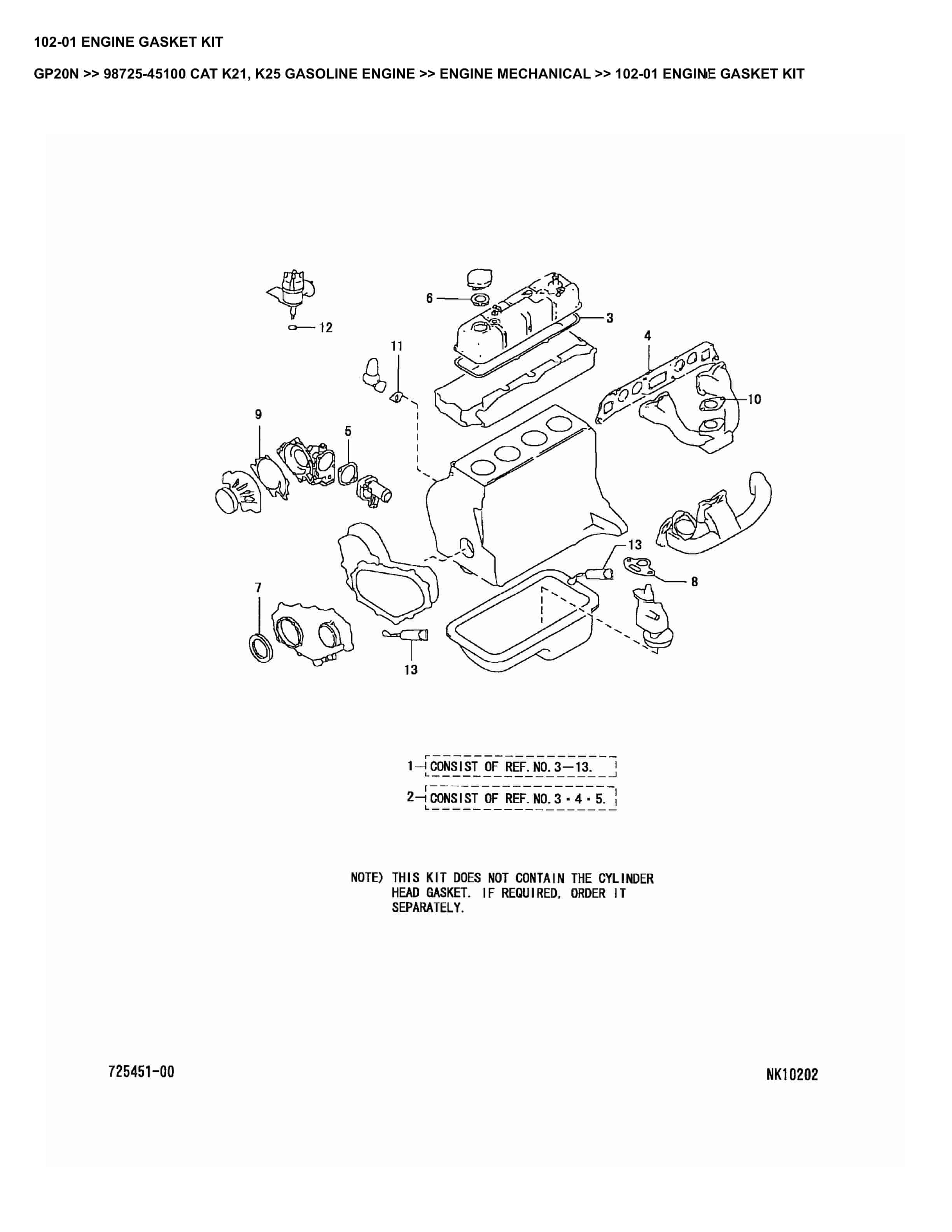
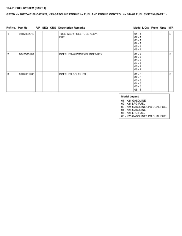
Caterpillar GP20N Parts Manual 98725-45100
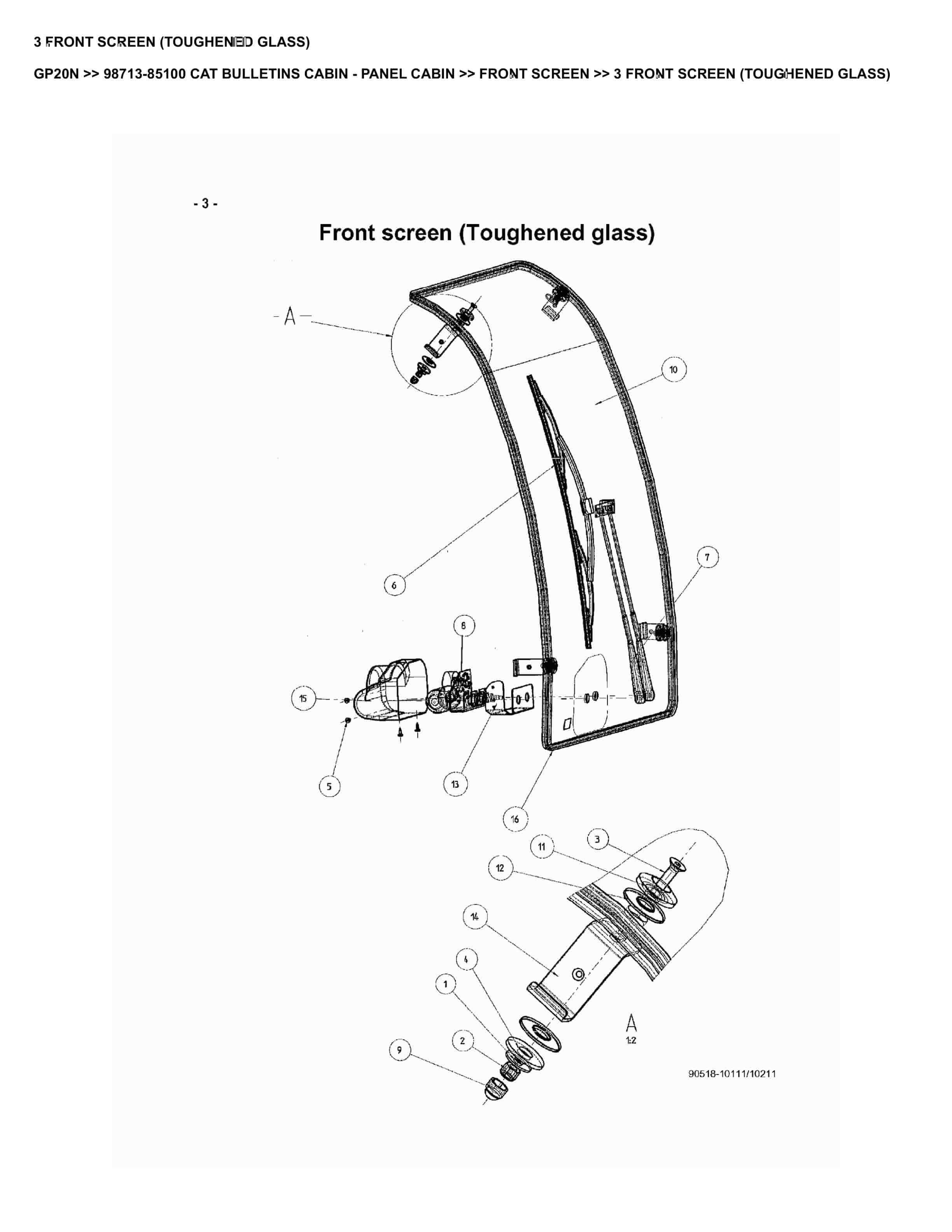
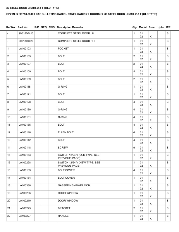
Caterpillar GP20N Parts Manual 98713-85100
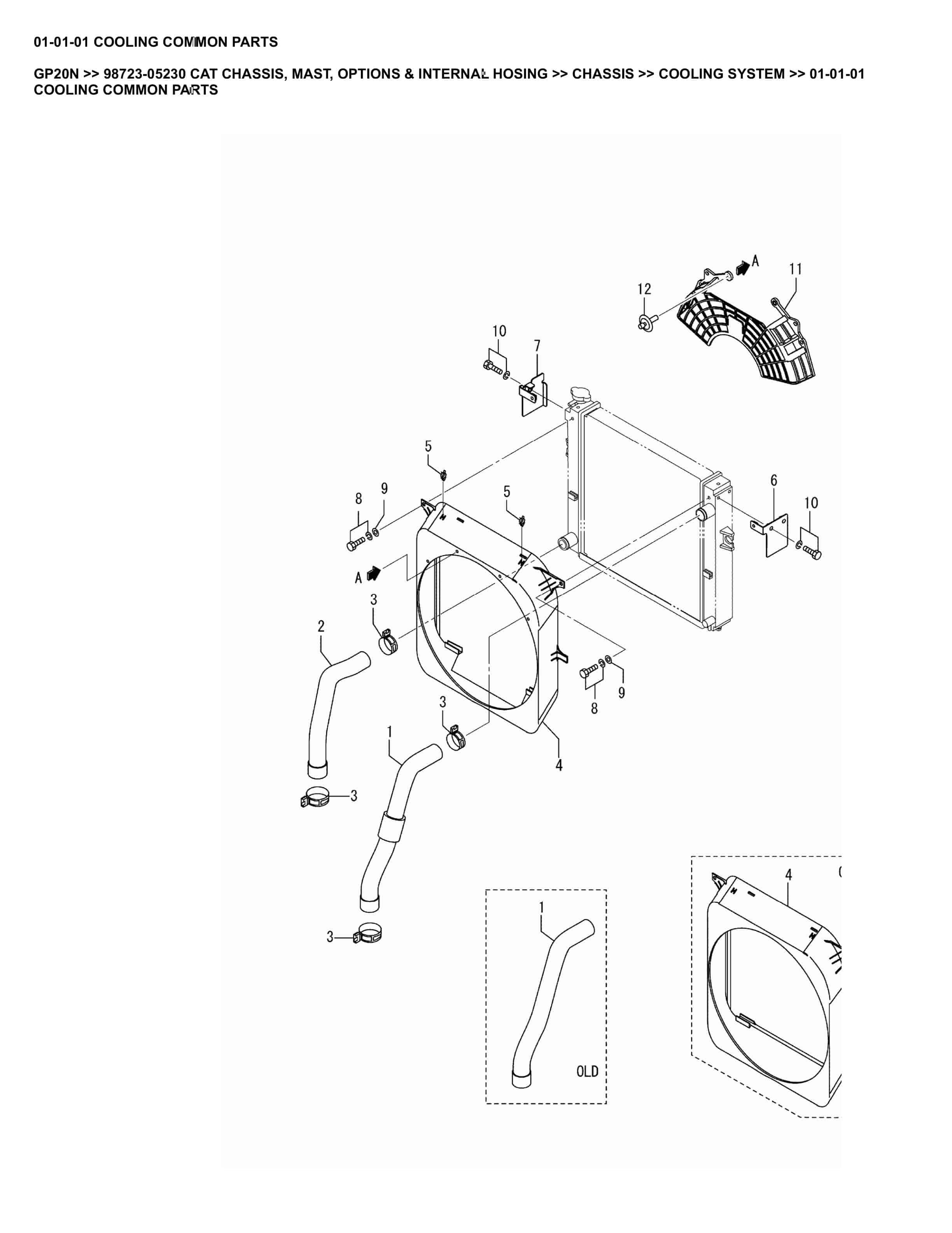
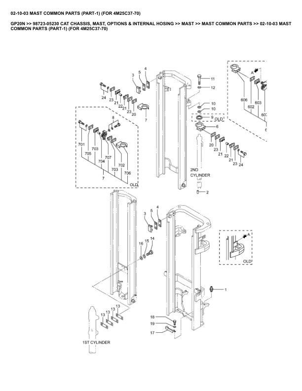
Caterpillar GP20N Parts Manual 98723-05230
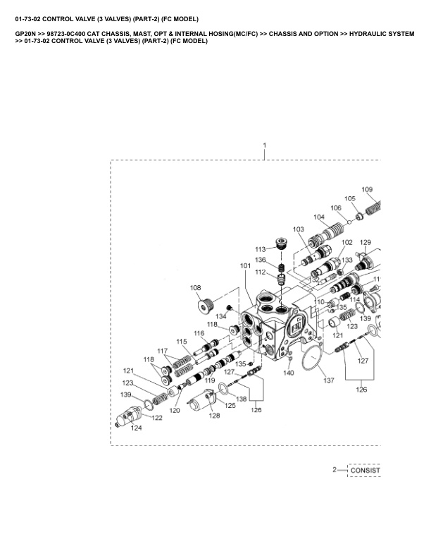
Caterpillar GP20N Parts Manual 98723-0C400
Caterpillar GP20NT Parts Manual 98723-0C400


