No products in the cart.
Return to shop
$30.00
BT Parts Manual PDF
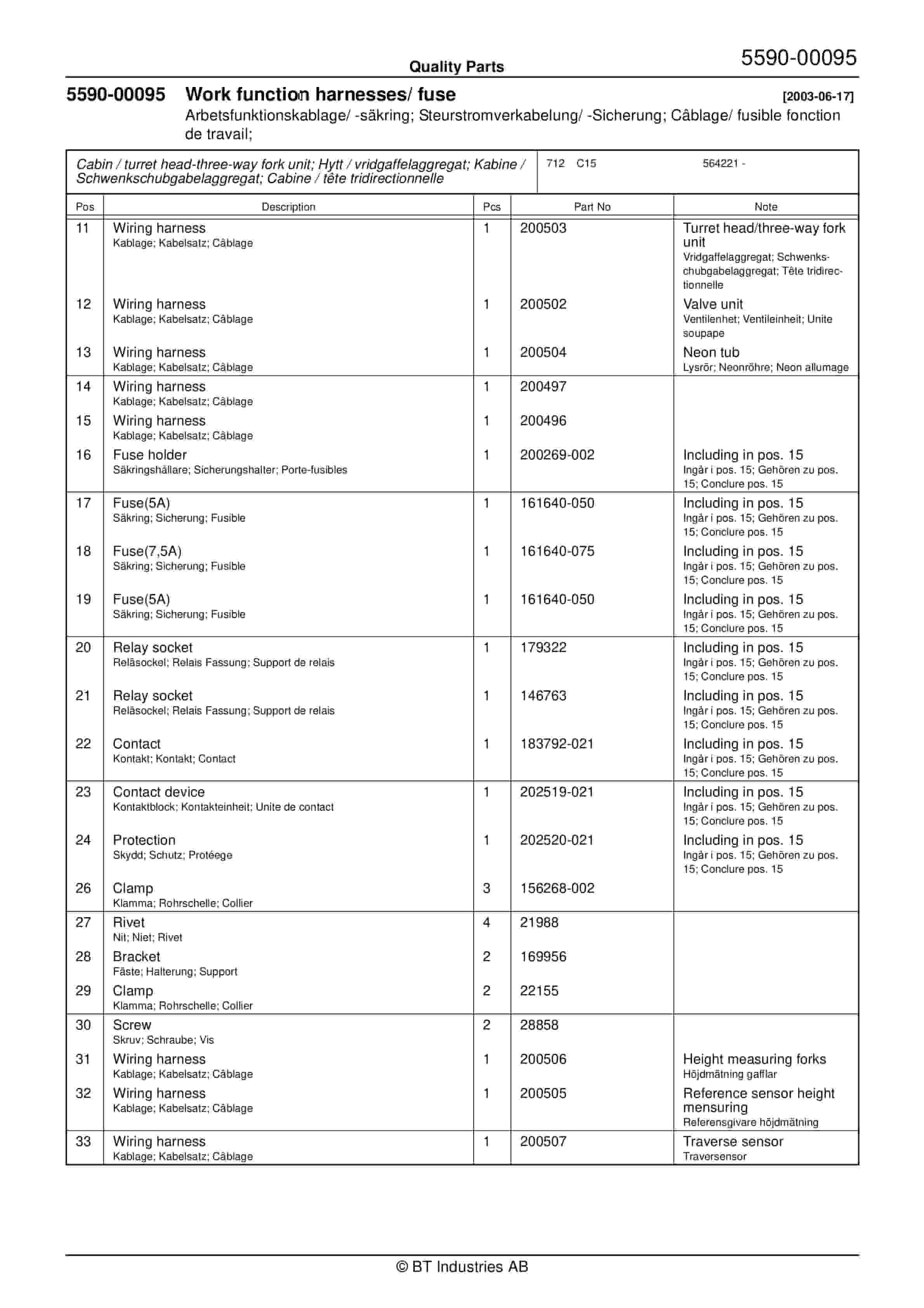
BT C15 564221AA Quality Parts 211455
BT C4E 200NL Spare Parts Catalog 0350175R1-0
BT Appendix II For Lift Pump And Motor Assembly
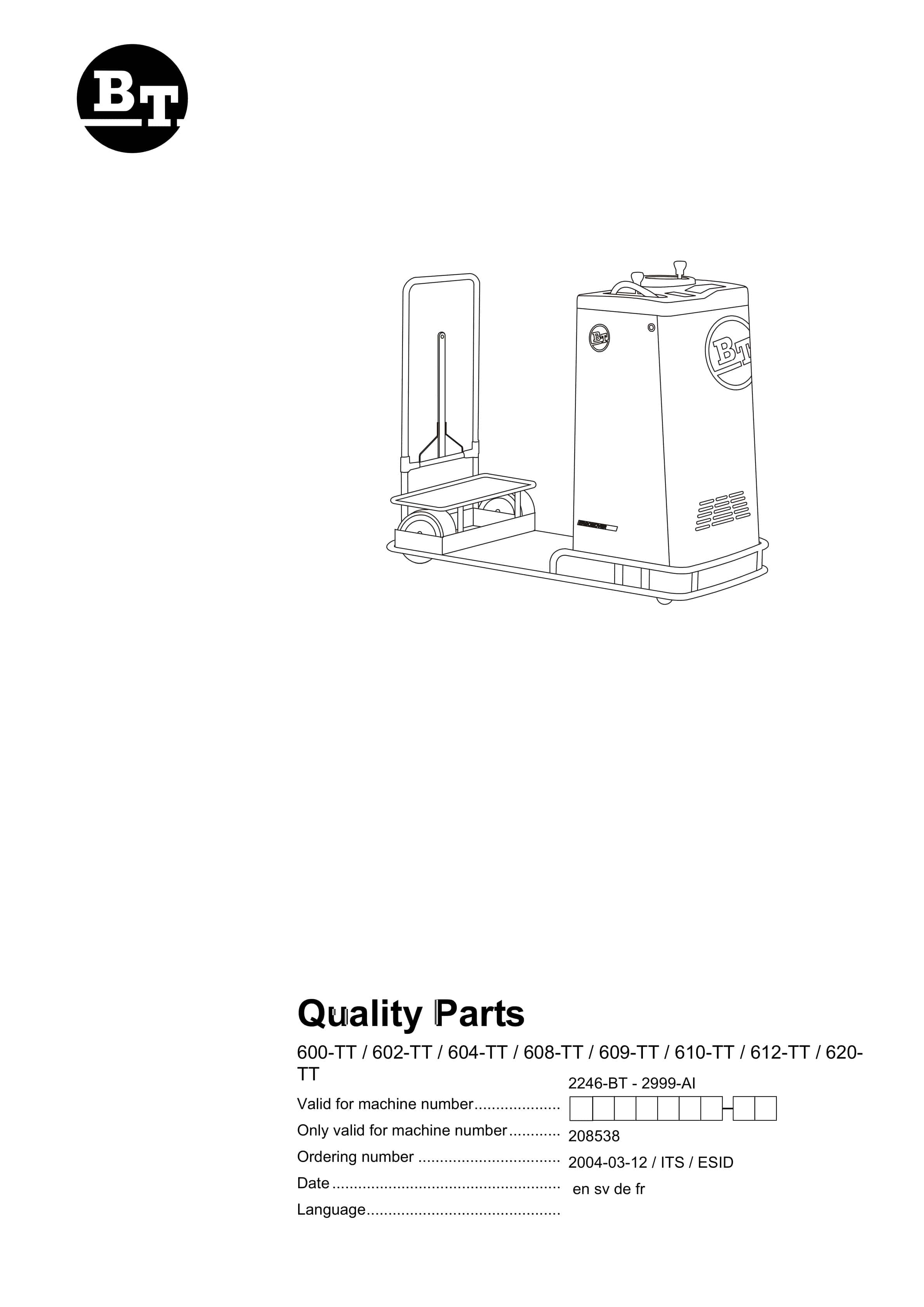
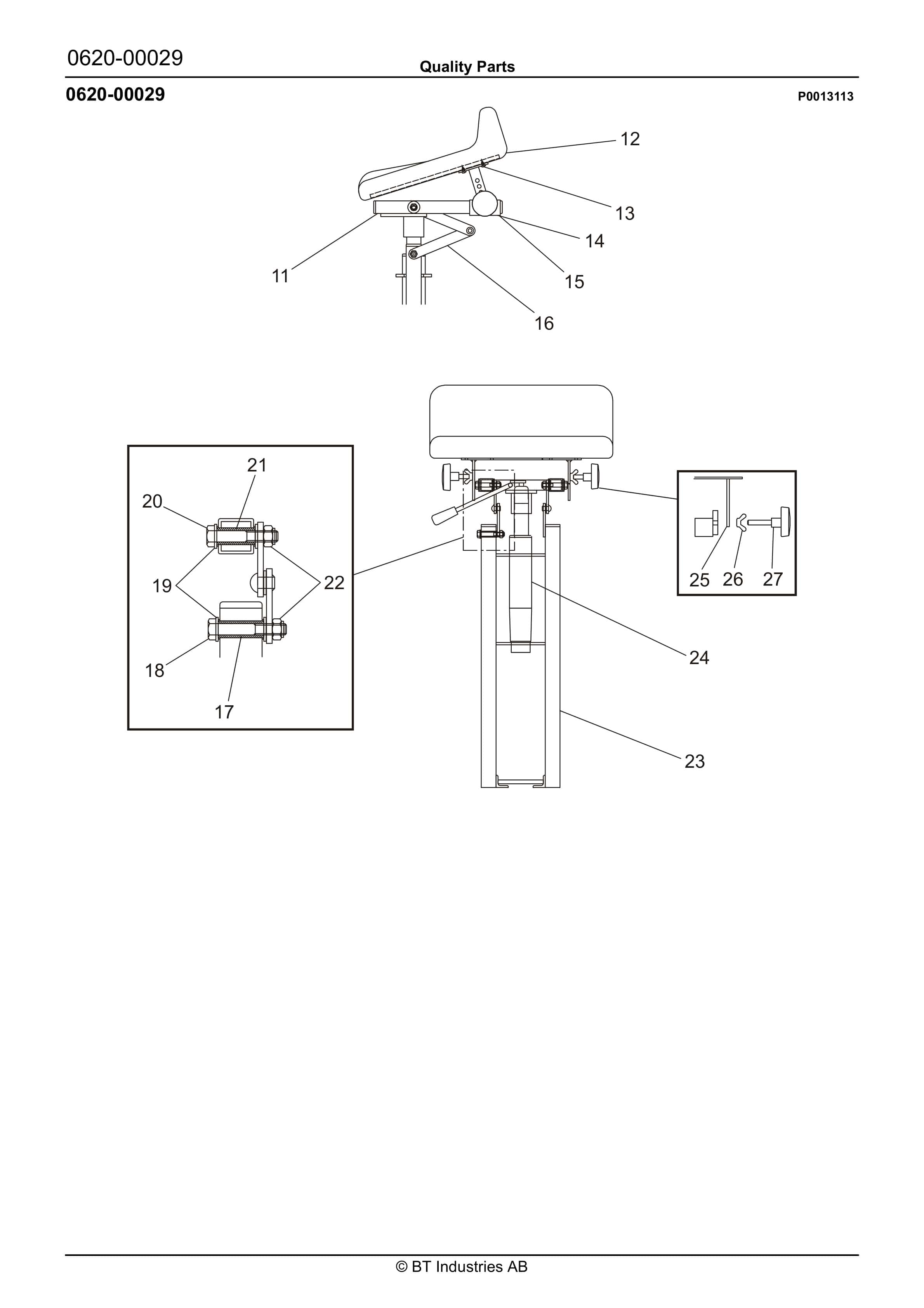
BT 600-TT, 602-TT, 604-TT, 608-TT, 609-TT, 610-TT, 612-TT, 620-TT Quality Parts 208538
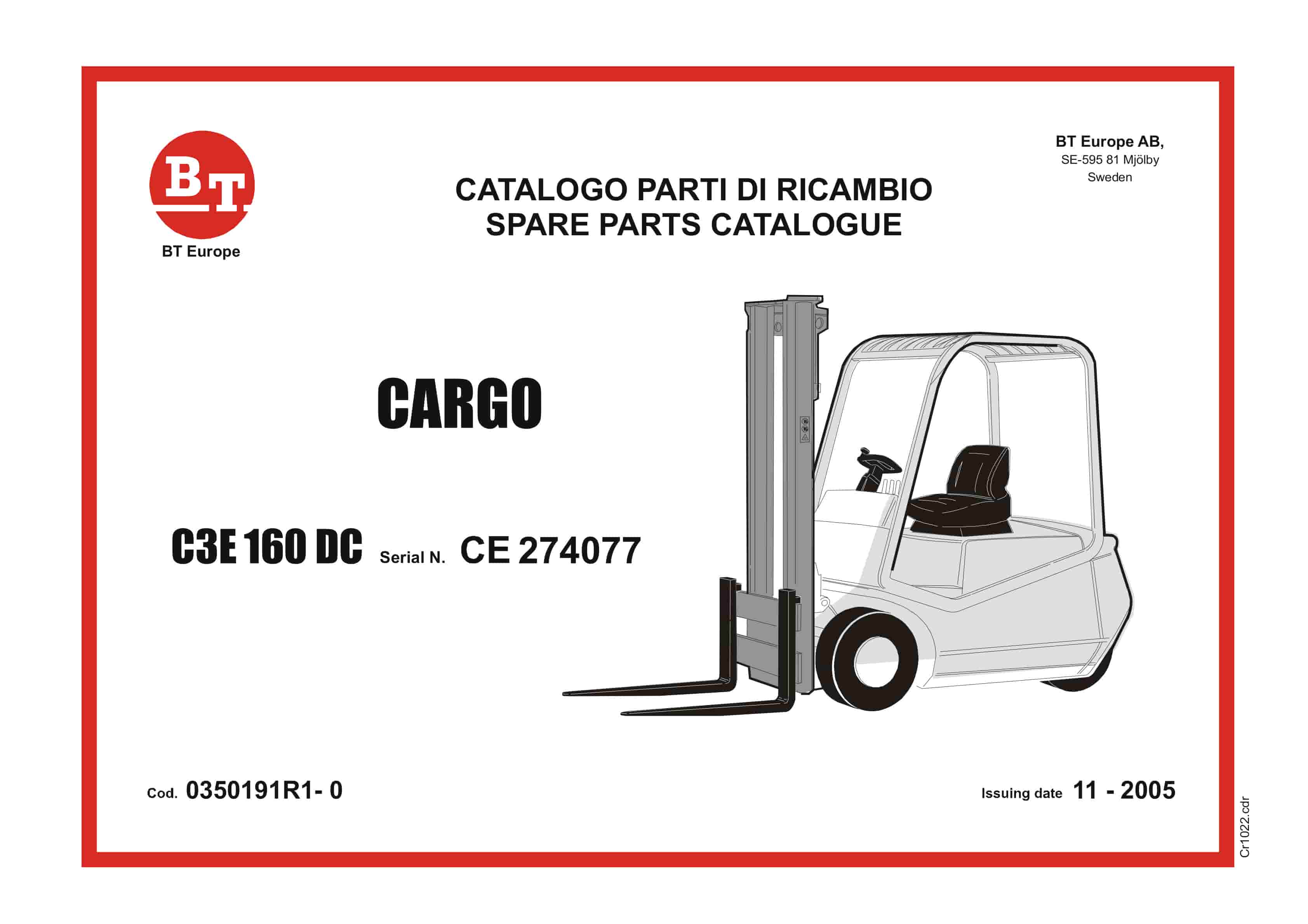
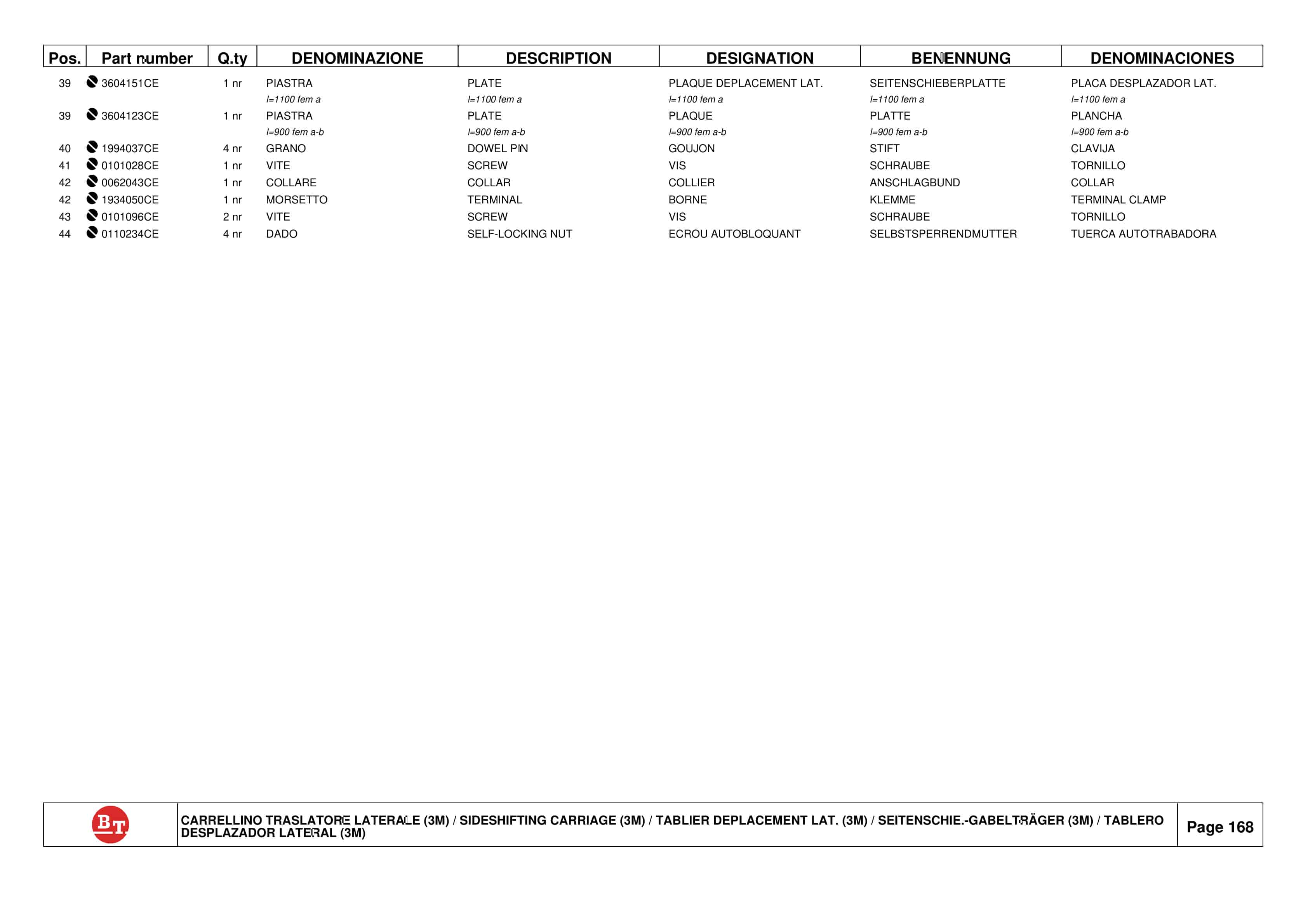
BT CARGO C3E 160 DC Spare Parts Catalog 0350191R1-0
BT C4E 300NV Spare Parts Catalog 0350178R1-0
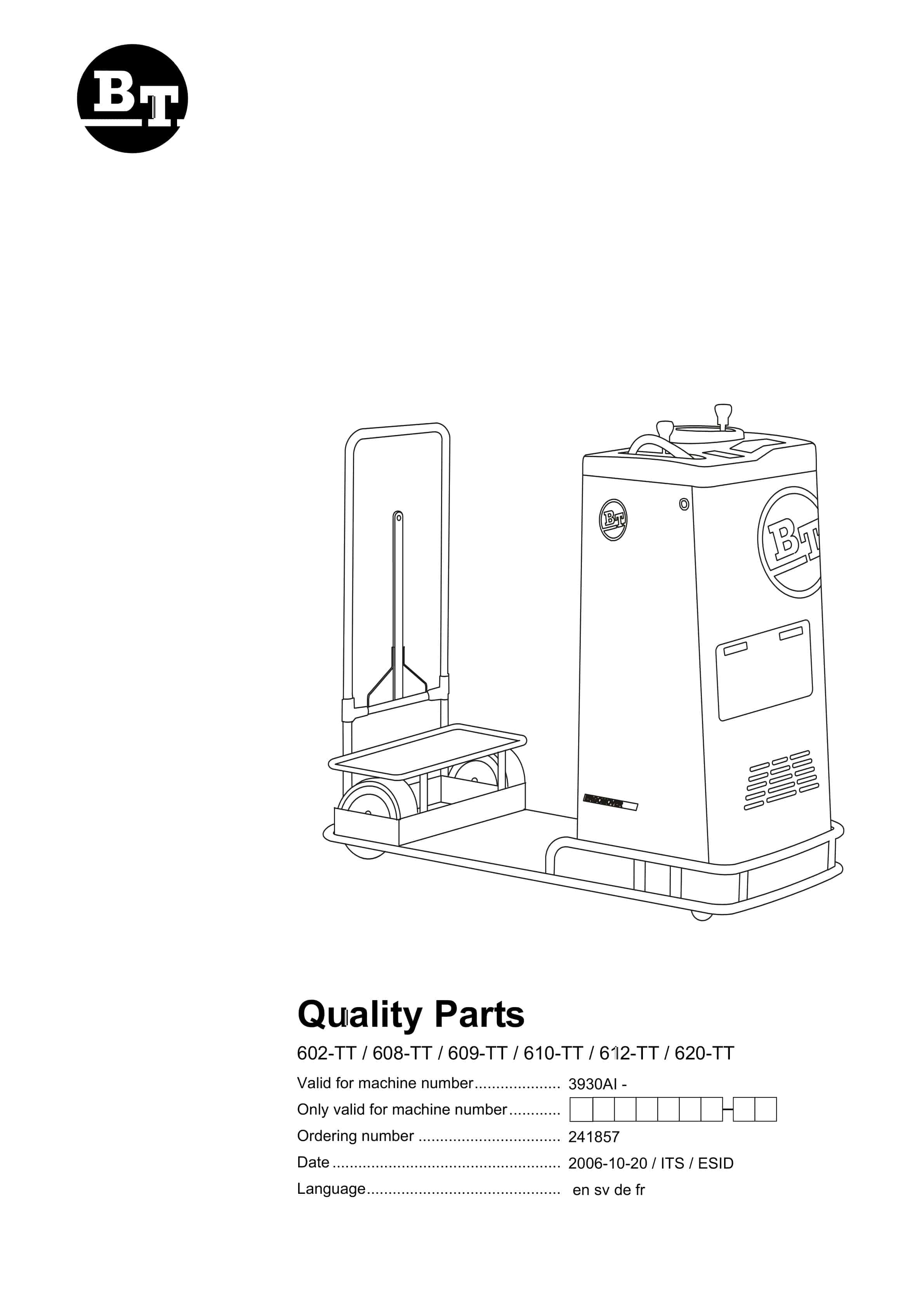
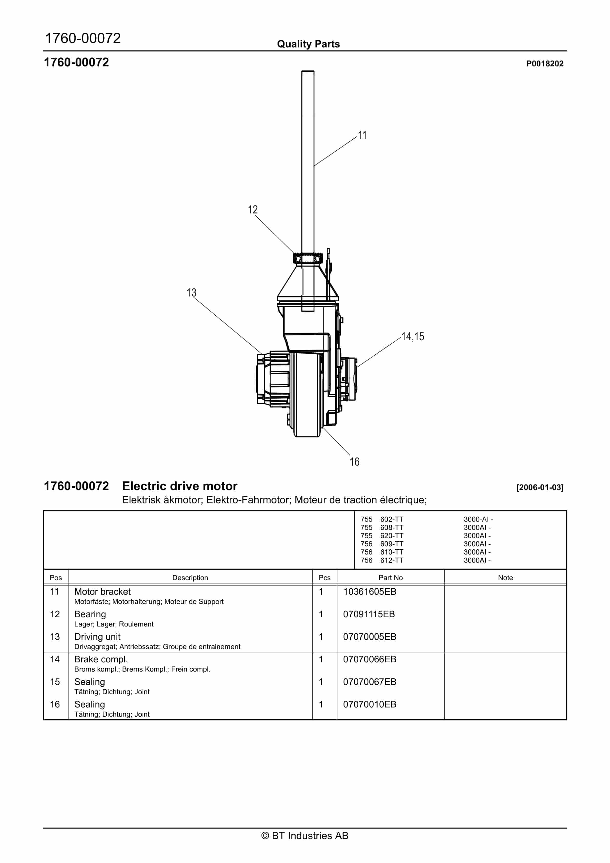
BT 602-TT, 608-TT, 609-TT, 610-TT, 612-TT, 620-TT Quality Parts 241857
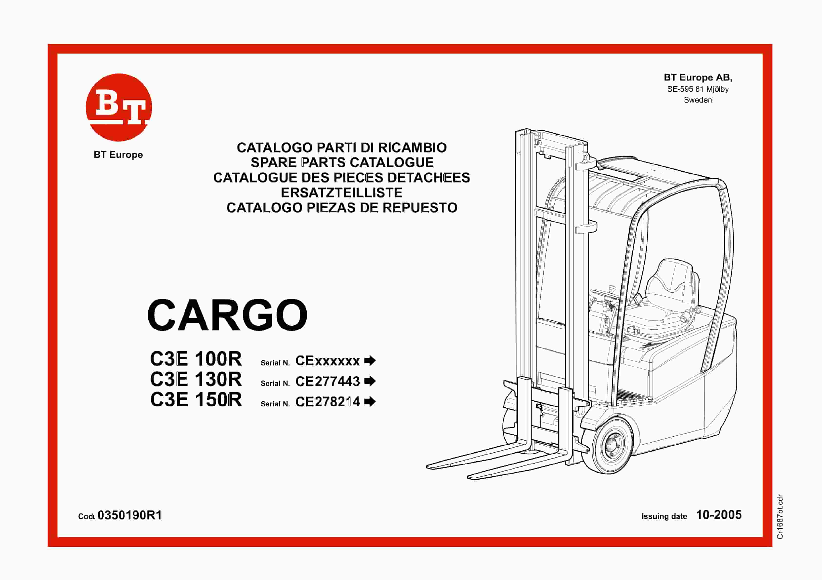
BT CARGO C3E 100R, C3E 130R, C3E 150R Spare Parts Catalog 0350190R1
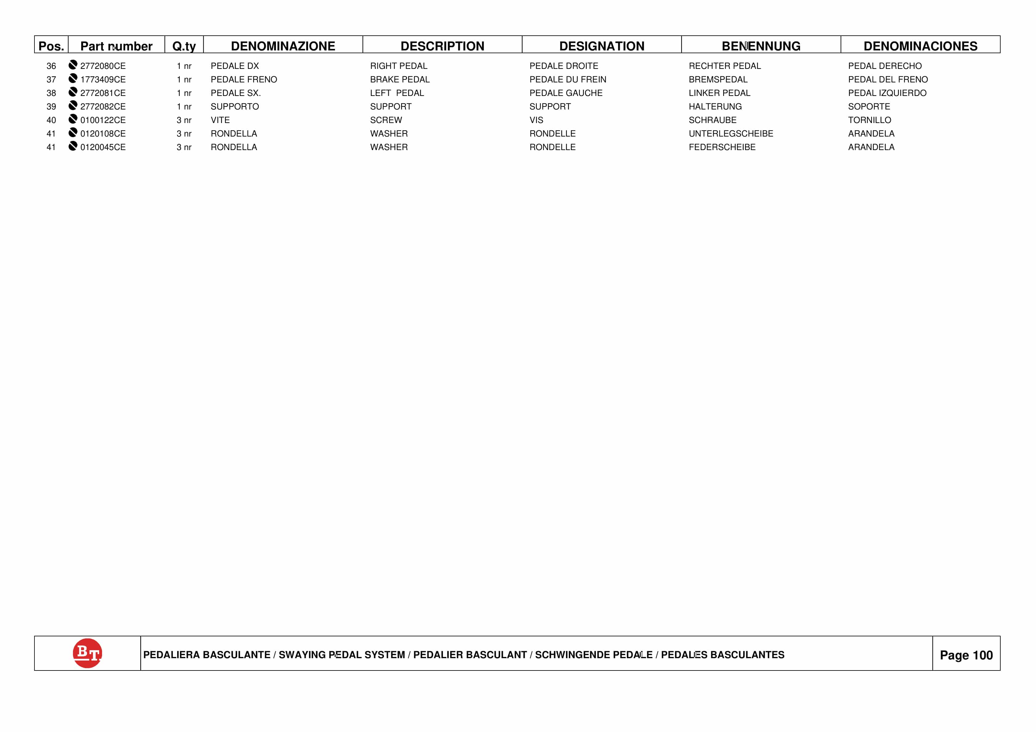
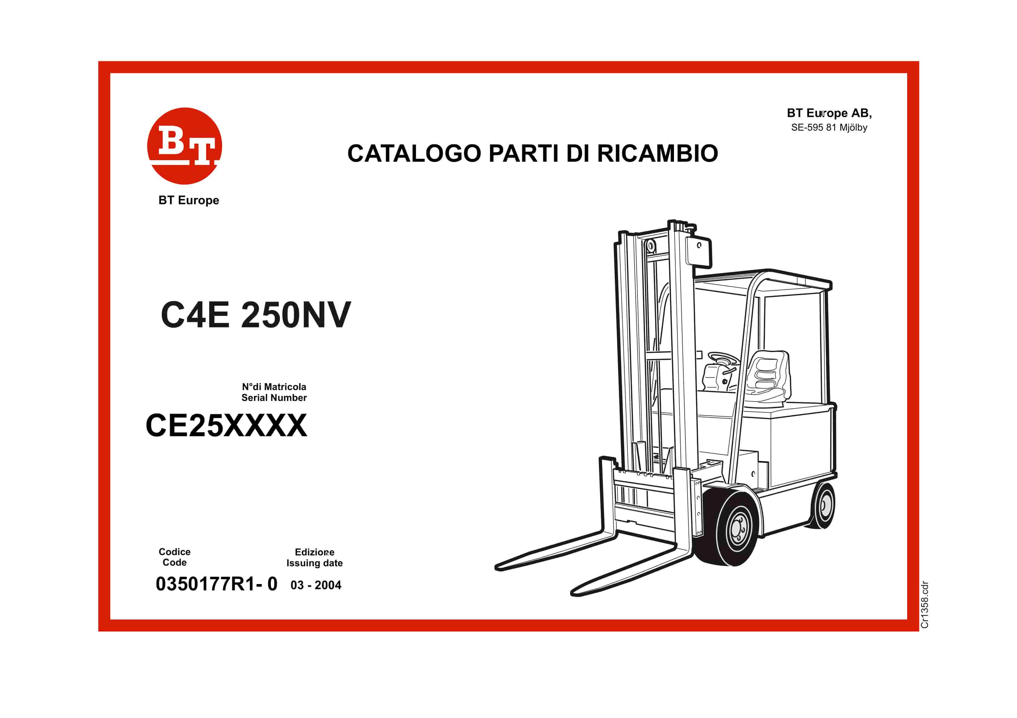
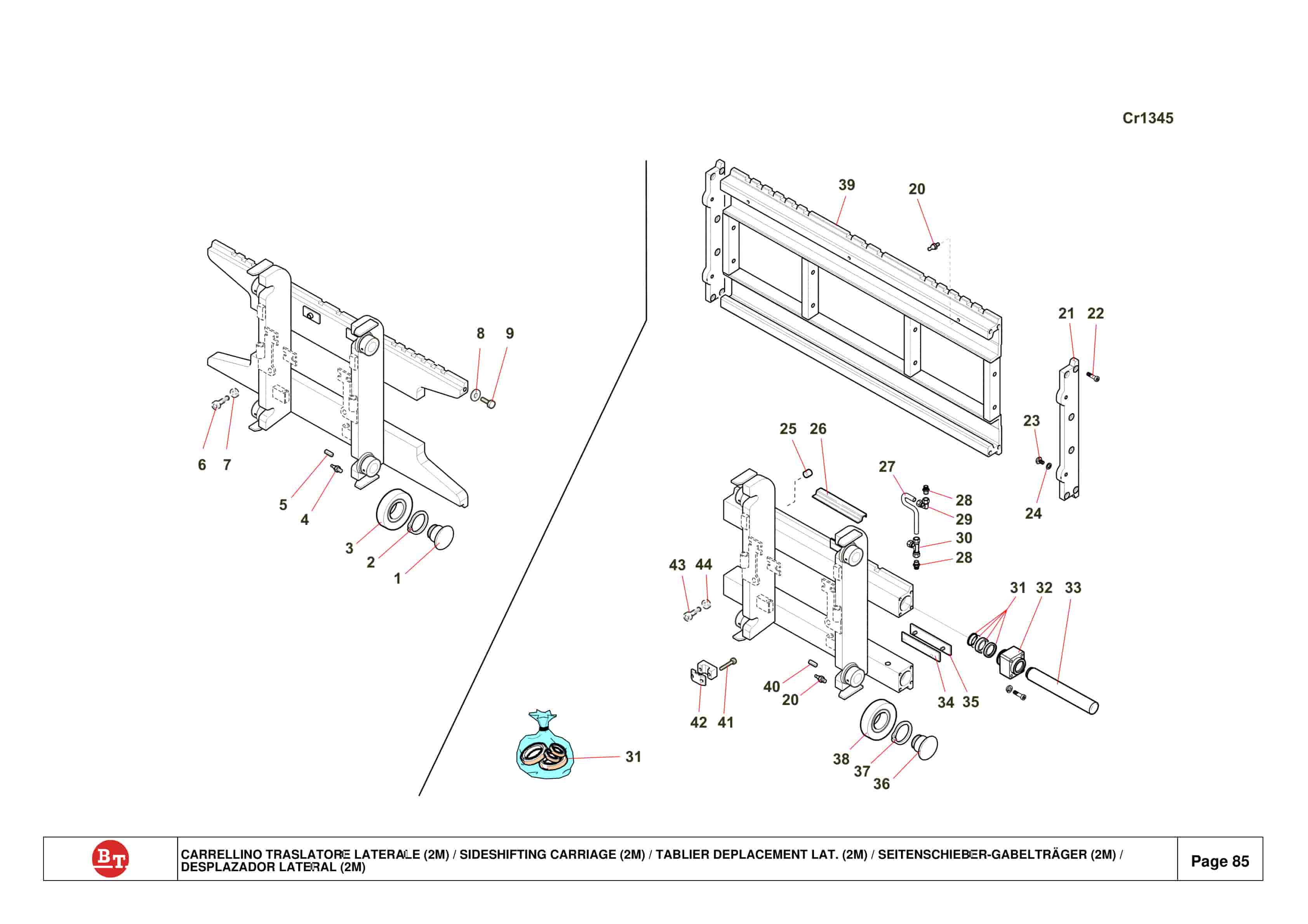
BT C4E 250NV Spare Parts Catalog 0350177R1-0
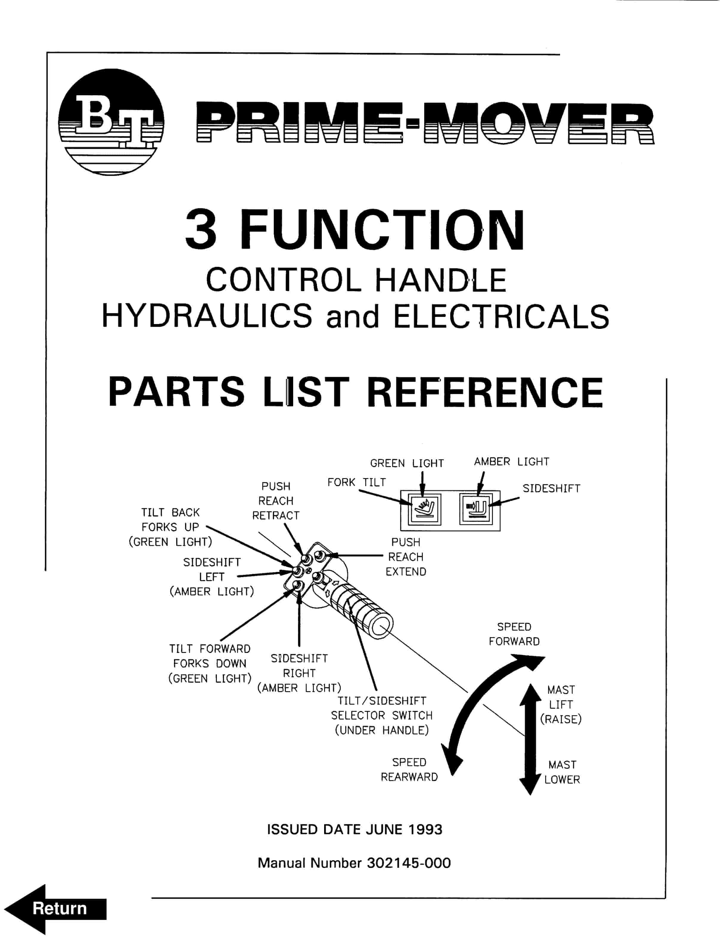
BT 3 Function Control Handle Parts List Reference 302145-000


