BT ORION P24 Operator Manual 173317-040
$20.00
- Type Of Manual: Operator Manual
- Manual ID: 173317-040
- : Operator Manual PDF
- Number of Pages: 62
- Size: 2.4MB
- Format: PDF
Category: BT Operator Manual PDF
-
Model List:
- ORION P24
- 1. BT ORION P24
- 1.1. Valid from serial number 350497AA-
- 1.2. Order number 173317-040
- 1.2.1. Issued 2000-08-25 ITS
- 1.2.1.1. It is important that you read this Operators Manual for your own safety
- 2. Safety regulations
- 2.1. Warning symbols
- 2.1.1. Warning levels
- 2.1.1.1. DANGER
- 2.1.1.2. WARNING
- 2.1.1.3. CAUTION
- 2.1.2. Prohibitory symbols
- 2.1.2.1. NO SMOKING
- 2.1.2.2. NAKED FLAMES PROHIBITED
- 2.1.2.3. GENERAL PROHIBITION
- 2.1.3. Ordinance symbols
- 2.1.3.1. SAFETY SHOES
- 2.1.3.2. PROTECTIVE GLASSES
- 2.2. General safety regulations
- 2.2.1. Operating the truck
- 2.2.2. Operators responsibility
- 2.2.3. Working area
- 2.2.4. Driving and conduct while driving
- 2.2.5. Handling loads
- 2.2.6. Parking the truck
- 2.2.7. Handling the battery
- 2.2.8. Maintenance and repair
- 3. Warning and information plates and symbols
- 3.1. Modification plate
- 3.2. Travel direction
- 3.3. Hydraulic control Lift
- 3.4. Hydraulic control Lower
- 3.5. Signal/Horn
- 3.6. Identification plate
- 3.7. Serial number
- 3.8. Hydraulic oil filling
- 3.9. Lifting points
- 4. Presentation of the truck
- 4.1. Intended application of the truck
- 4.2. Forbidden application of the truck
- 4.3. Truck data
- 4.3.1. Truck type
- 4.3.2. ORION P24
- 4.4. Truck dimensions
- 4.4.1. ORION P24
- 4.4.2. Value in mm
- 4.5. Identification plate CE
- 4.6. Modification plate
- 5. Main components
- 5.1. Tiller arm The truck can be controlled by the operator standing on the rideon platform or wa…
- 5.2. Identification plate With model designation, serial number, year of manufacture, weight witho…
- 5.3. Protective gates A higher speed of 12 km/h is possible with the gates folded out, while the t…
- 5.4. Covers Easily opened and removable which allows good access when servicing.
- 5.5. Electric panel With fuses and contacts positioned for easy access during service. 24 Volts tr…
- 5.6. Serial number The serial number plate fitted to the chassis.
- 5.7. Drive unit with brake Suspended drive unit with electromagnetic brake, drive motor, gears and…
- 5.8. Platform Folding ride-on platform which stays in the folded down position.
- 5.9. Platform switch Switch for control of the speed range and brake function.
- 5.10. Hydraulic unit Pump motor, pump, valves and oil tank integrated in a compact unit.
- 5.11. Support castor wheels Two support castor wheels to ensure stability.
- 5.12. Lift cylinders Easily accessible when the battery is removed.
- 5.13. Fork carriage The forks are held in the horizontal position by a link system. Fork carriage …
- 5.14. Battery 24 V with different Ah values. Stands on rollers to facilitate replacement. Can be c…
- 5.15. Battery disconnector and battery connector The battery is charged via the permanently fitted…
- 6. Controls and instruments
- 6.1. Switch for safety reversing
- 6.2. Travel direction selector and speed control
- 6.3. Control for lifting and lowering the forks
- 6.4. Horn
- 6.5. Display
- 6.6. Keybord (Option)
- 6.7. Key switch
- 6.8. Emergency switch off
- 6.9. Battery disconnector and battery connector
- 6.10. Lock for protective gates
- 6.11. Tiller arm and brake
- 6.12. Switch for safety reversing (1)
- 6.13. Travel direction selector and speed control (2)
- 6.14. Control for lifting and lowering the forks (3)
- 6.15. Horn (4)
- 6.16. Display (5)
- 6.16.1. Numerical field (A)
- 6.16.2. Hour meter indicator (B)
- 6.16.3. Parameter control (C)
- 6.16.4. Battery indicator (D)
- 6.16.5. Error indicator (E)
- 6.17. Function
- 6.18. Keybord (6) (Option)
- 6.19. Key switch (7)
- 6.20. Emergency switch off (8)
- 6.21. Battery disconnector and battery connector (9)
- 6.22. Lock for protective gates (10)
- 6.23. Tiller arm and brake (11)
- 6.24. Display and programming
- 6.24.1. Display
- 6.24.2. Programming
- 6.24.2.1. Truck with key
- 6.24.2.2. Truck with keyboard
- 6.24.3. Parameters
- 6.24.3.1. Parameter type
- 6.24.3.2. Min./ Max.
- 6.24.3.3. Std. value
- 6.25. Warning codes
- 6.25.1. WARNING
- 6.25.2. Code No.
- 6.25.3. Error type
- 6.25.4. Probable cause
- 6.26. Error codes
- 6.26.1. Code No
- 6.26.2. Error type
- 6.26.3. Probable cause
- 7. Accessories
- 7.1. Fixed backrest
- 7.2. Fixed side protectors
- 7.3. Load support
- 8. Driving
- 8.1. Starting the truck
- 8.1.1. WARNING
- 8.1.2. WARNING
- 8.2. Braking
- 8.3. Deceleration
- 8.4. Steering
- 8.4.1. WARNING
- 8.5. Parking the truck
- 8.5.1. WARNING
- 9. Transporting loads
- 9.1. WARNING
- 9.2. WARNING
- 9.3. WARNING
- 9.4. WARNING
- 9.5. WARNING
- 9.6. WARNING
- 9.7. WARNING
- 9.8. Loading and unloading
- 9.8.1. WARNING
- 9.9. Collecting a load
- 9.9.1. CAUTION
- 9.10. Depositing a load
- 9.10.1. CAUTION
- 10. Battery
- 10.1. Fitting the battery and battery lock
- 10.1.1. WARNING
- 10.2. Changing the battery
- 10.2.1. WARNING
- 10.2.2. WARNING
- 10.2.3. WARNING
- 10.3. Charging the battery
- 10.3.1. GENERAL PROHIBITION
- 10.3.2. Battery (Ah)
- 10.3.3. Charger (A)
- 10.3.3.1. WARNING
- 10.3.4. Before charging
- 10.3.4.1. WARNING
- 10.3.5. During charging
- 10.3.6. After charging
- 10.3.6.1. CAUTION
- 10.4. Battery maintenance
- 10.4.1. WARNING
- 10.4.2. Each week
- 10.4.3. Each month
- 10.4.3.1. Temperature C
- 10.4.3.2. Density g/cm3
- 11. Daily service and function checks
- 11.1. WARNING
- 11.2. Check points
- 12. Maintenance
- 12.1. Safety regulations with maintenance work
- 12.1.1. WARNING
- 12.1.2. WARNING
- 12.1.3. WARNING
- 12.1.4. CAUTION
- 12.1.5. WARNING
- 12.2. Maintenance work that is to be carried out by the operator
- 12.3. Maintenance work that may be carried out by trained maintenance personnel
- 12.4. Cleaning and washing
- 12.4.1. External cleaning
- 12.4.2. Cleaning the motor compartment
- 12.4.3. Electrical components
- 12.5. Maintenance chart
- 12.5.1. Pos. no.
- 12.5.2. Work to carry out
- 12.5.2.1. Interval in hours – may vary due to application
- 12.5.2.2. Interval in days/weeks/months – may vary due to application
- 12.6. Lubrication chart
- 12.6.1. Service point
- 12.6.2. Interval/Running hours
- 12.6.3. Lubricant
- 12.6.3.1. hrs
- 12.6.3.2. hrs
- 12.7. Oil and grease specification
- 12.7.1. Lubricant
- 12.7.2. Specification
- 12.7.3. Application area
- 12.7.3.1. > – 15C
- 12.7.3.2. < – 15C
- 13. Transporting and storing the truck
- 13.1. The trucks dimensions and weight as standard
- 13.1.1. The trucks dimensions and weight
- 13.2. Lifting the truck
- 13.2.1. WARNING
- 13.2.2. WARNING
- 13.3. Towing and transporting a defective truck
- 13.3.1. Trucks that have a working electrical system
- 13.3.1.1. WARNING
- 13.3.2. Truck that has no electrical power
- 13.4. Storing the truck
- 13.4.1. Battery
- 13.4.2. Hydraulic system
- 13.4.3. Drive unit
- 13.5. Starting after a period of disuse
- 14. Recycling/discarding
- 14.1. Discarding the battery
- 14.2. Scrapping the truck
- 14.2.1. Chassis
- 14.2.2. Hydraulic system
- 14.2.3. Electrical system
Rate this product
You may also like
BT Operator Manual PDF
BT CMX60, CMX80 Electric Center Riding Pallet Truck Operator Manual 302823-005
$20.00
BT Operator Manual PDF
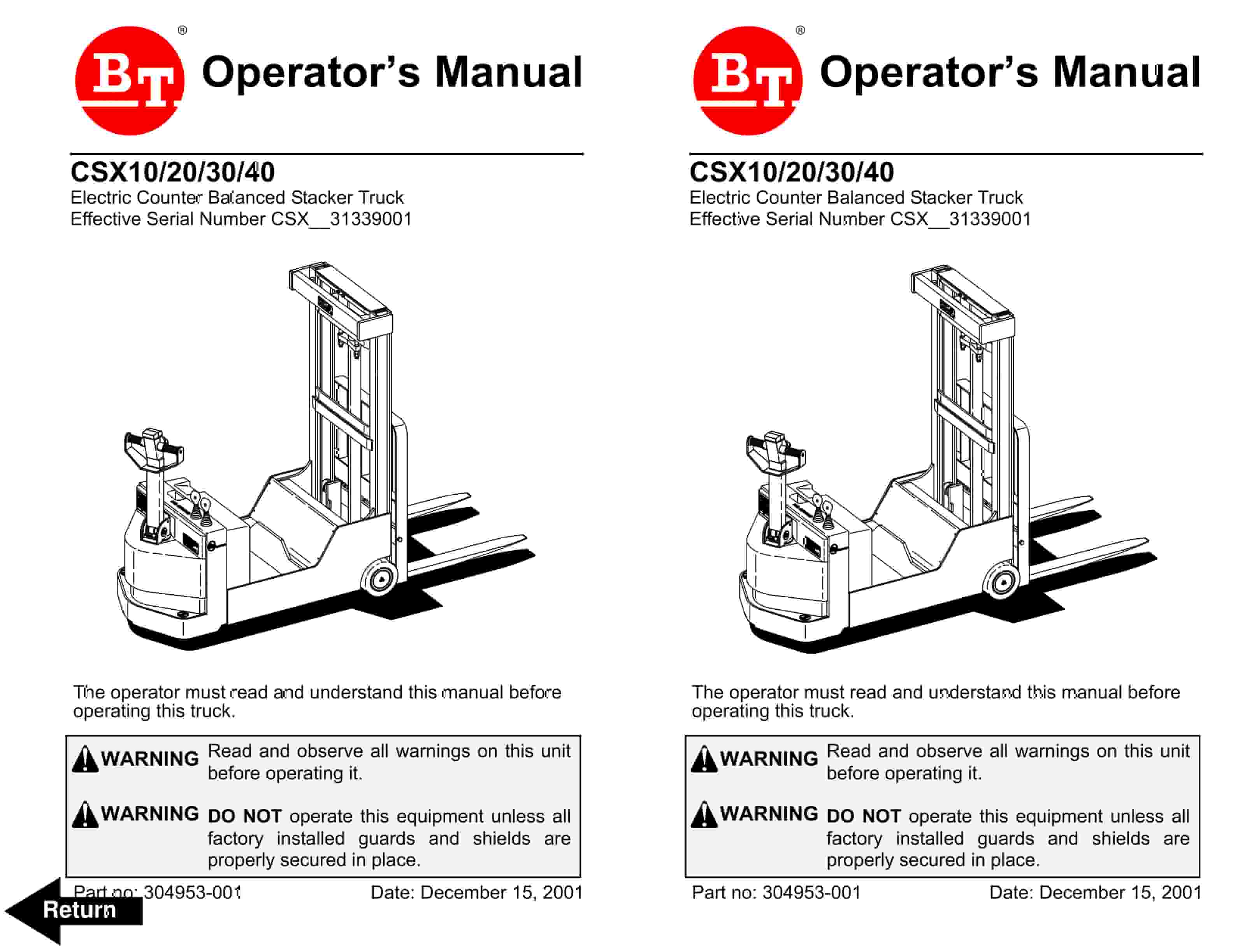
BT CSX Electric Counter Balanced Stacker Truck Operator Manual 304953-001
$20.00
BT Operator Manual PDF
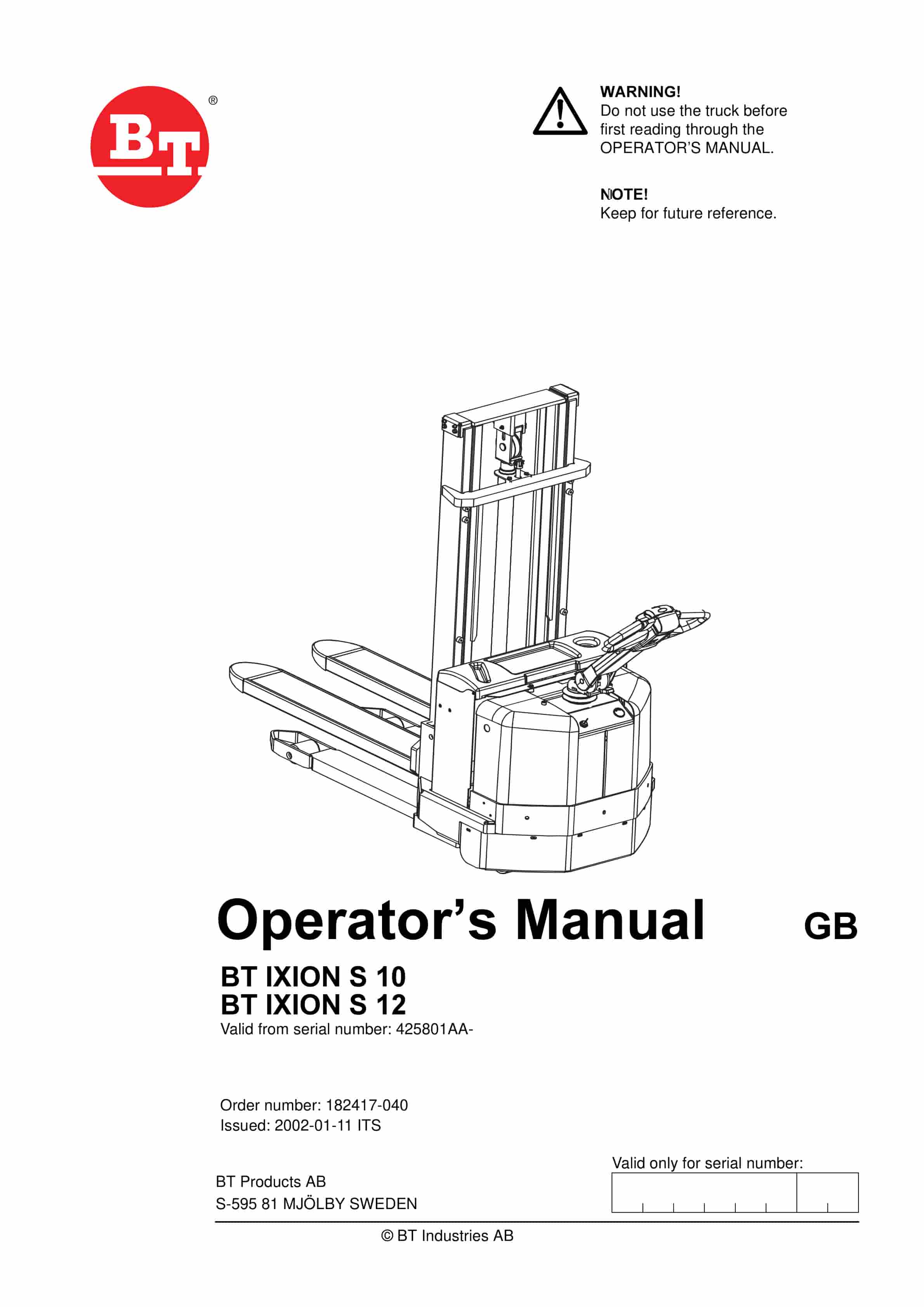
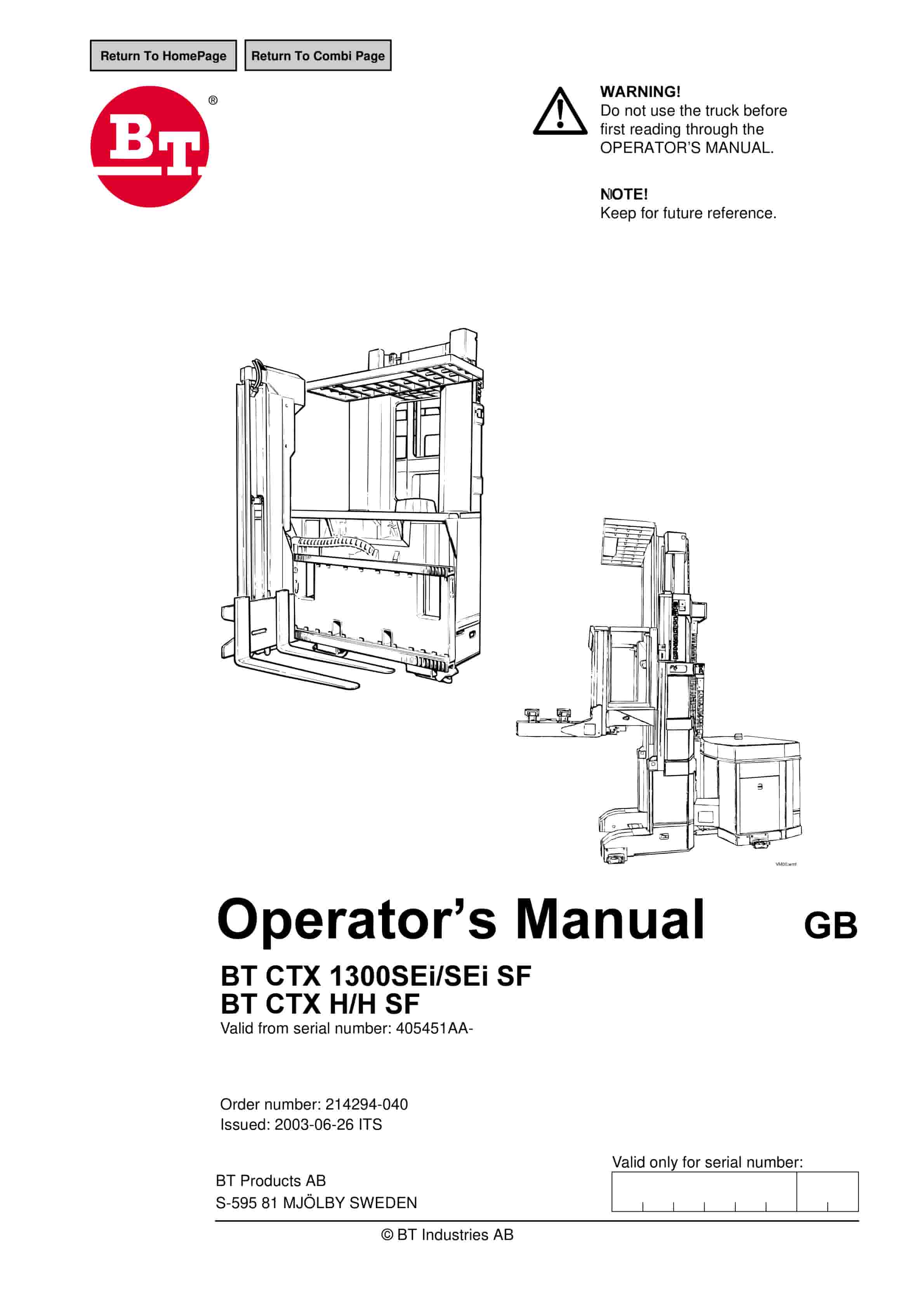
BT CTX1300SEi, CTX1300SEi SF, CTX H, CTX H SF Operator Manual 214294-040
$20.00


