


BT Parts Manual PDF
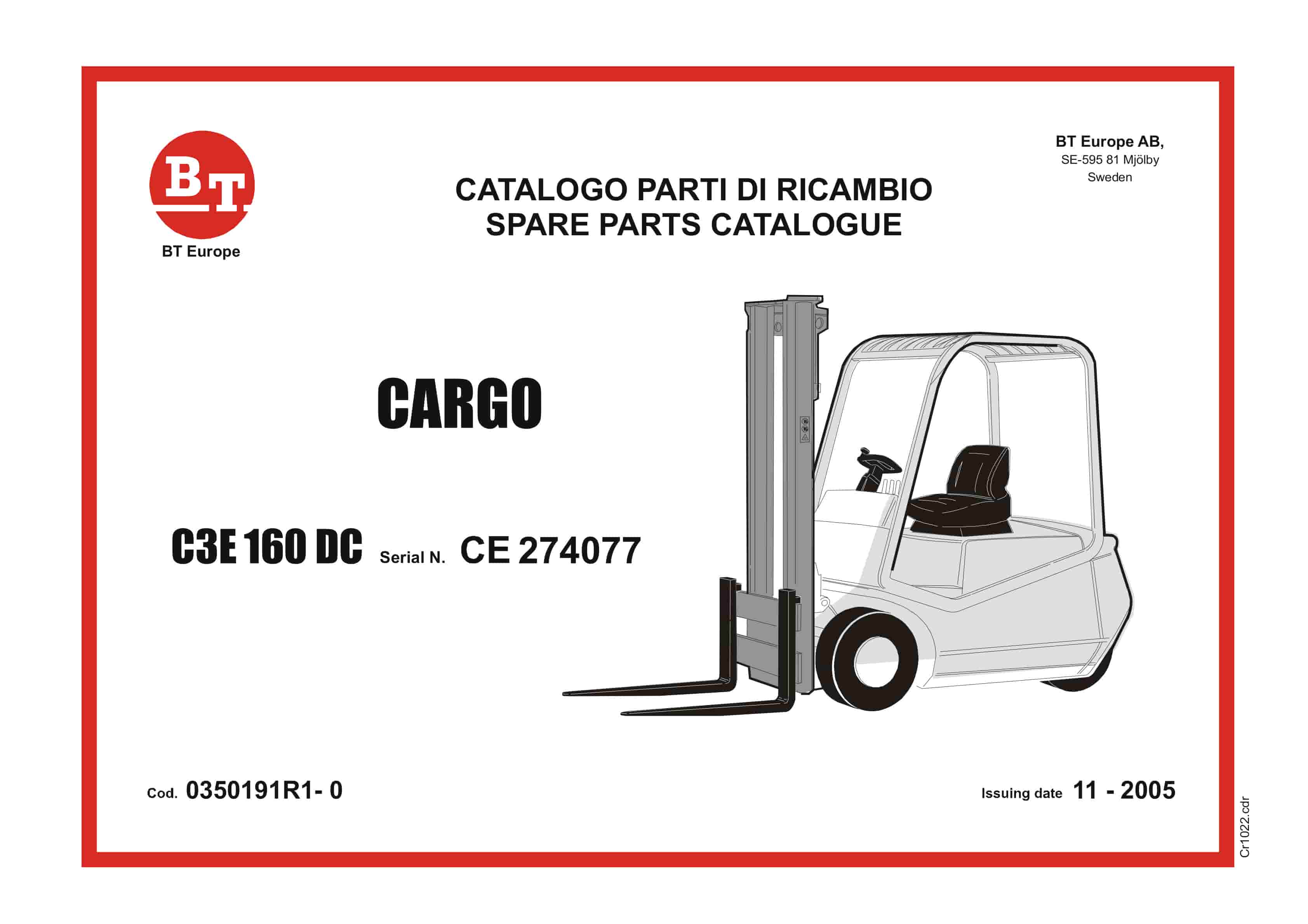
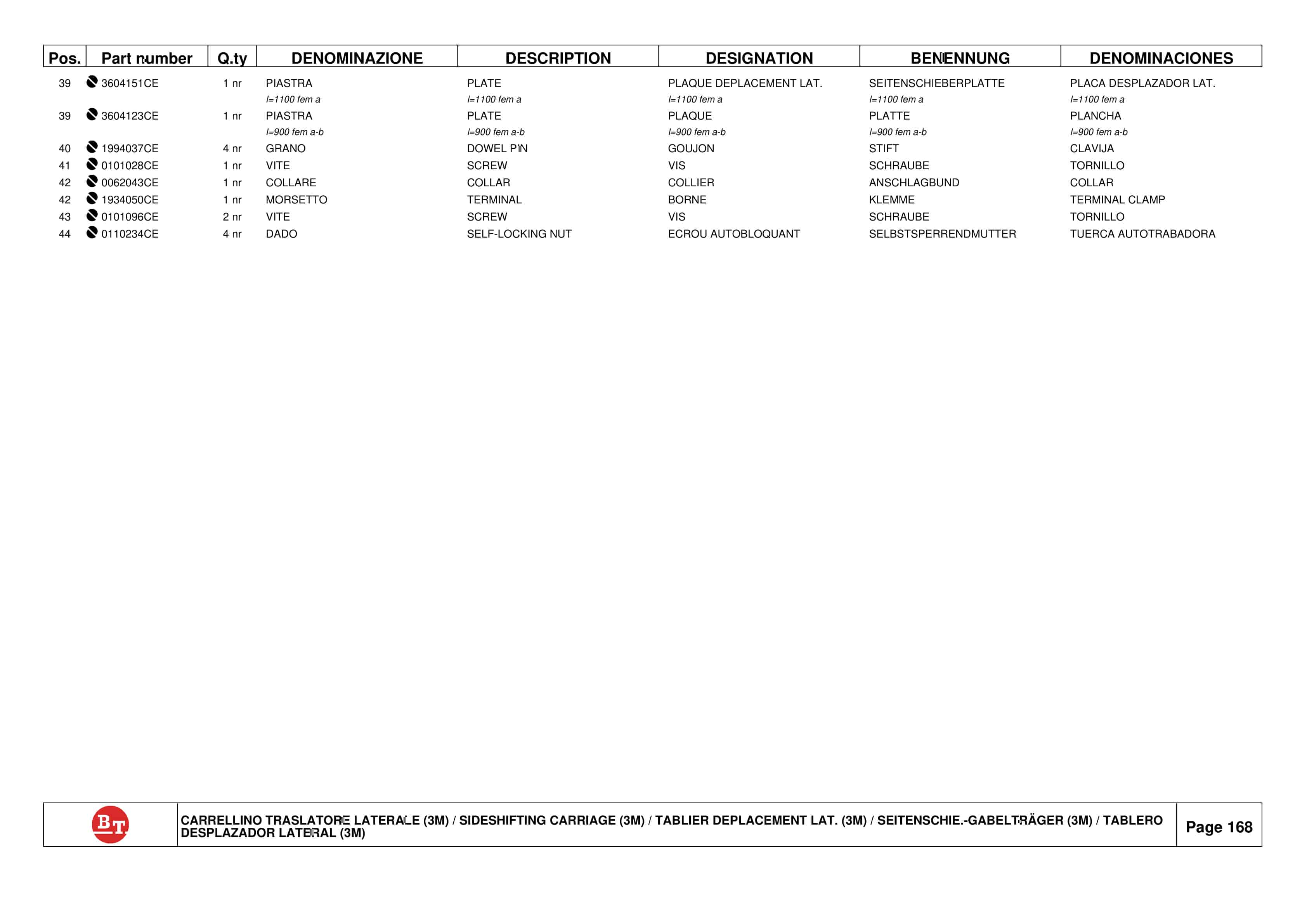
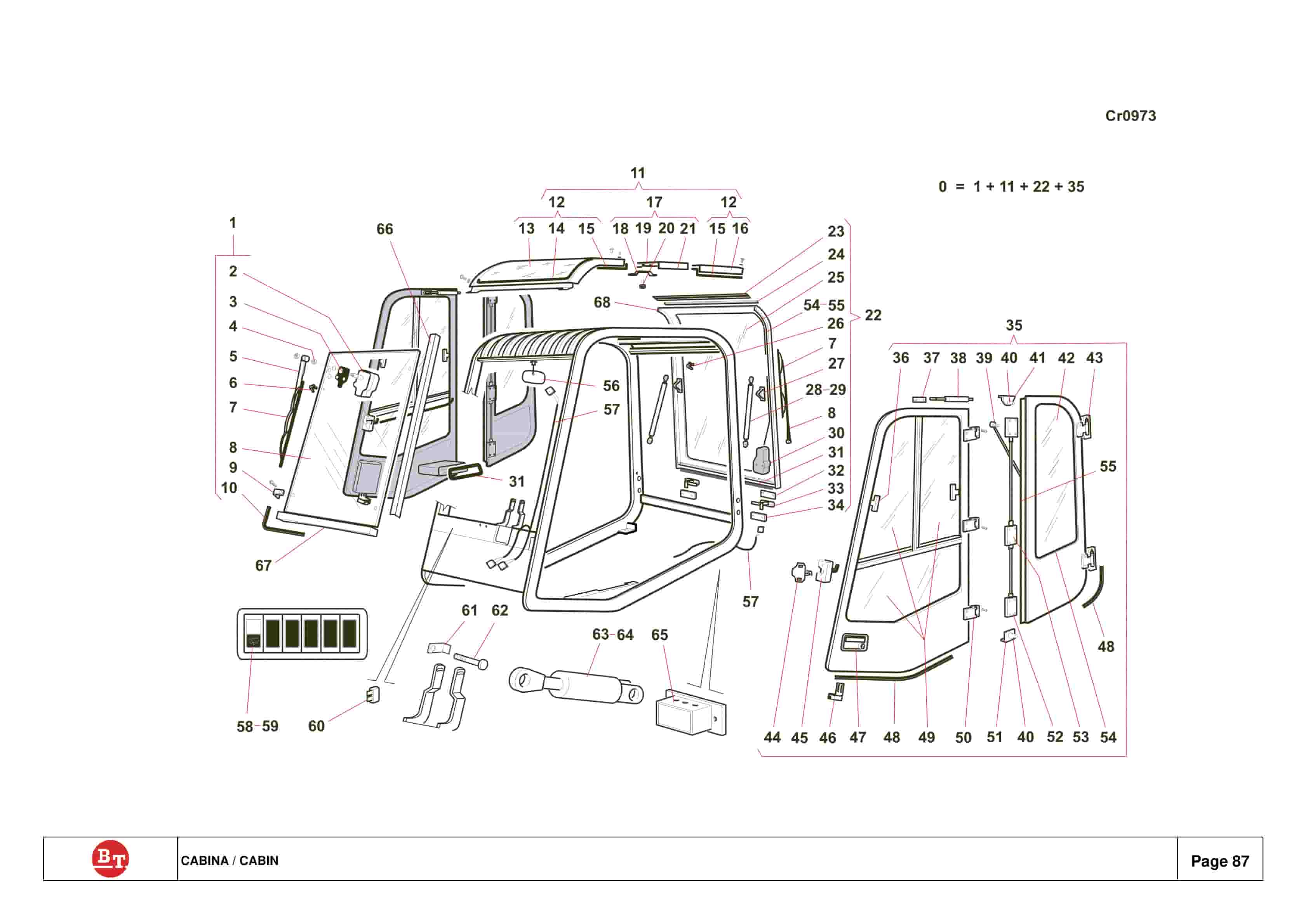
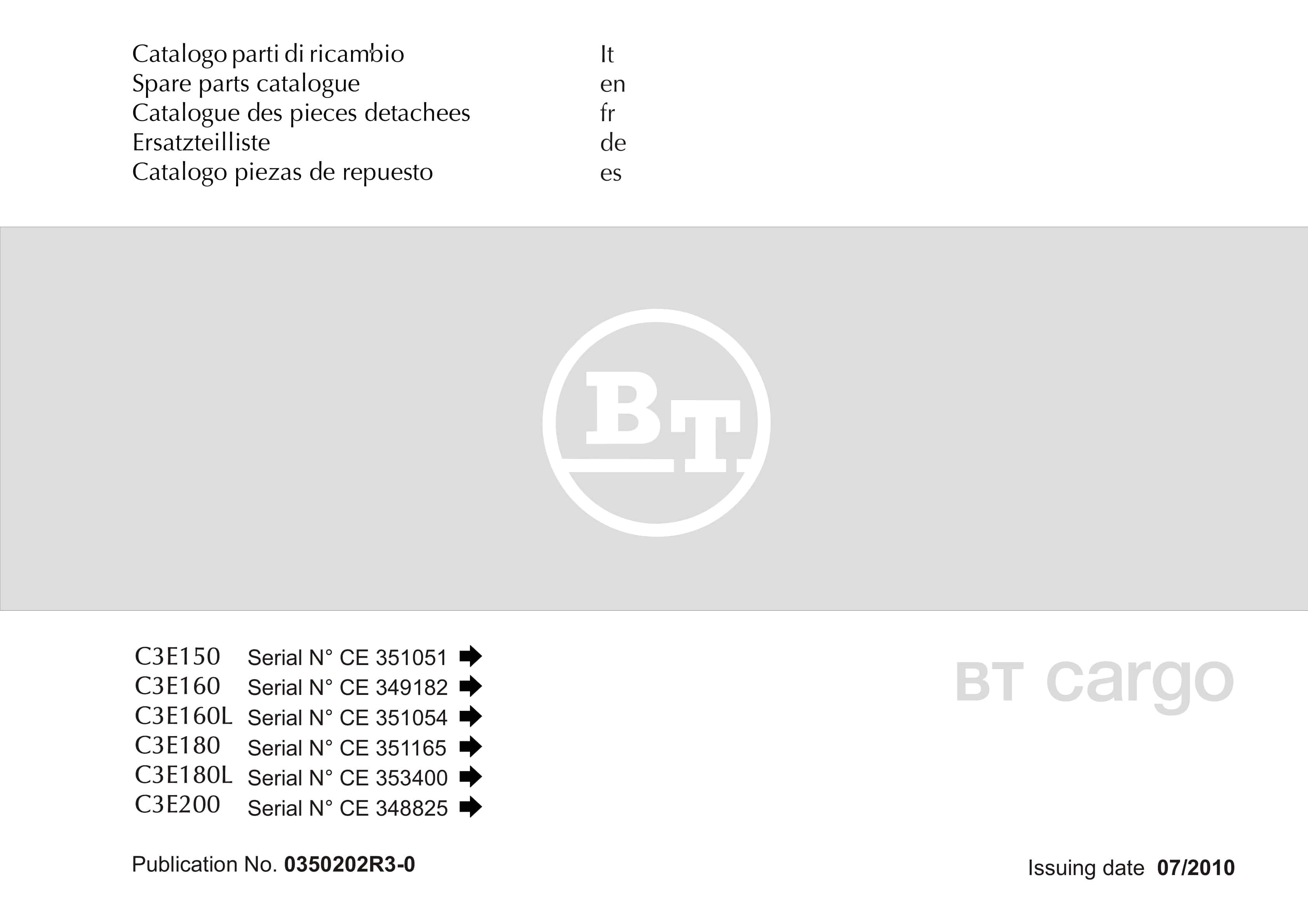
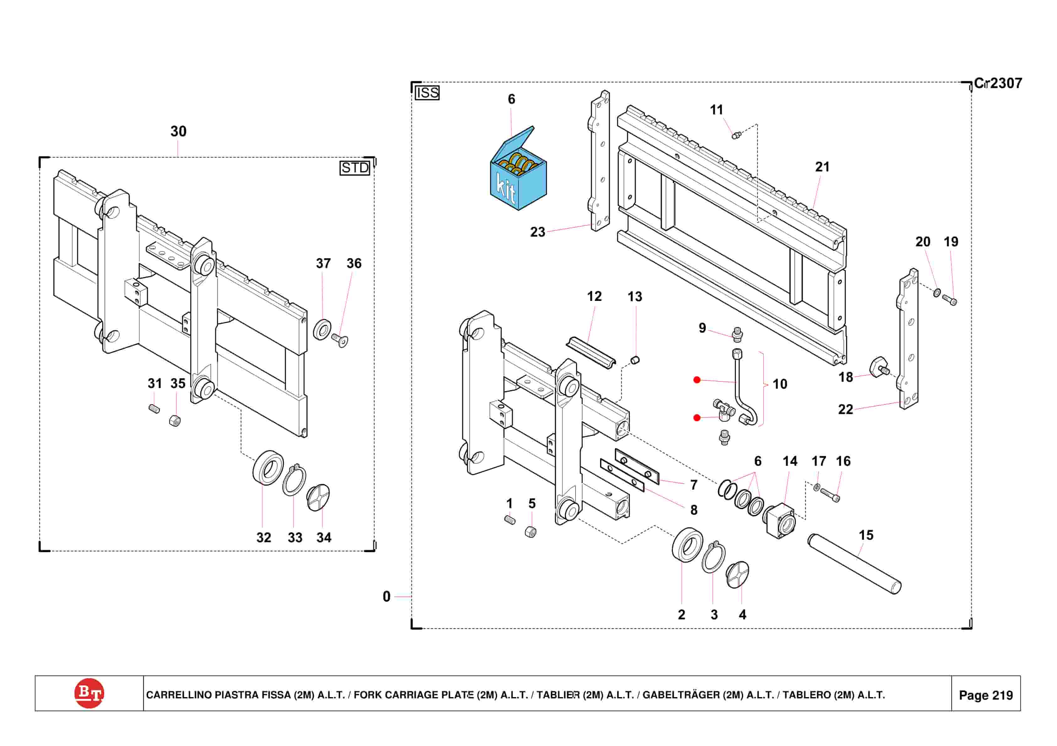
BT C3E150, C3E160, C3E160L, C3E180, C3E180L, C3E200 Spare Parts Catalog 0350202R3-0
$30.00
BT Parts Manual PDF
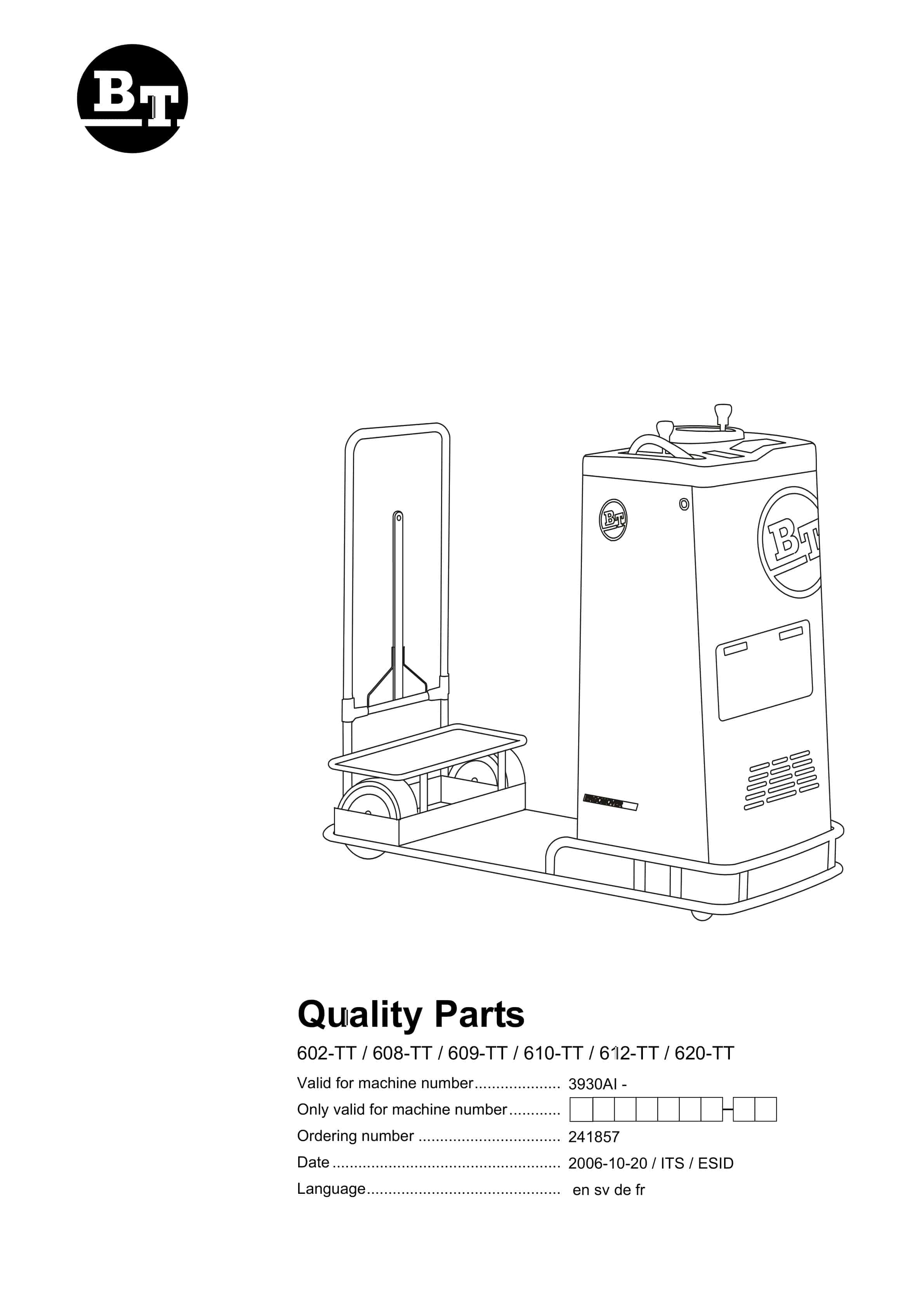
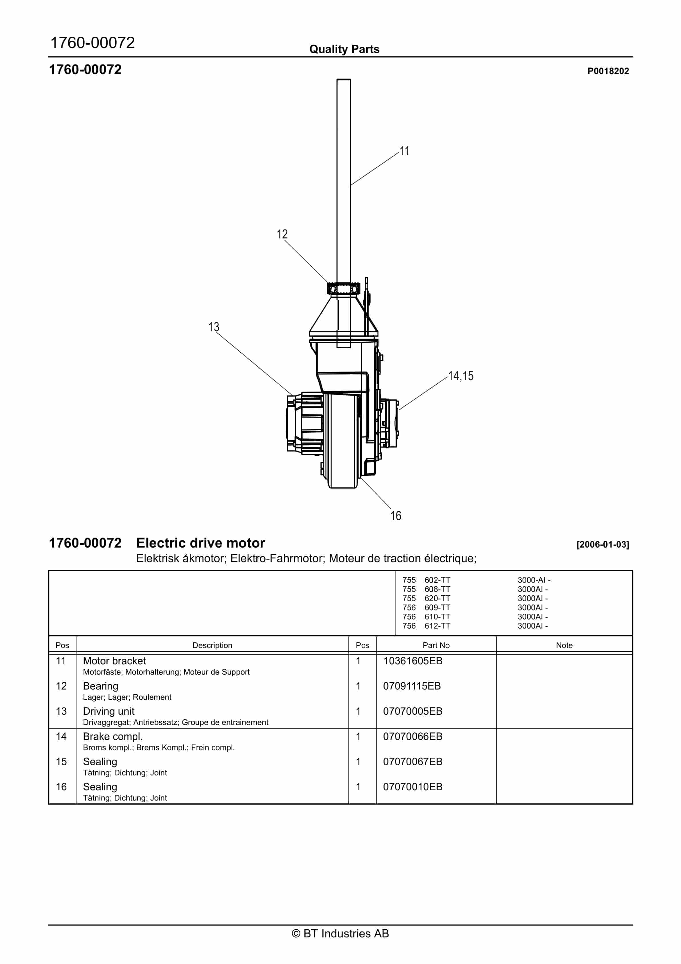
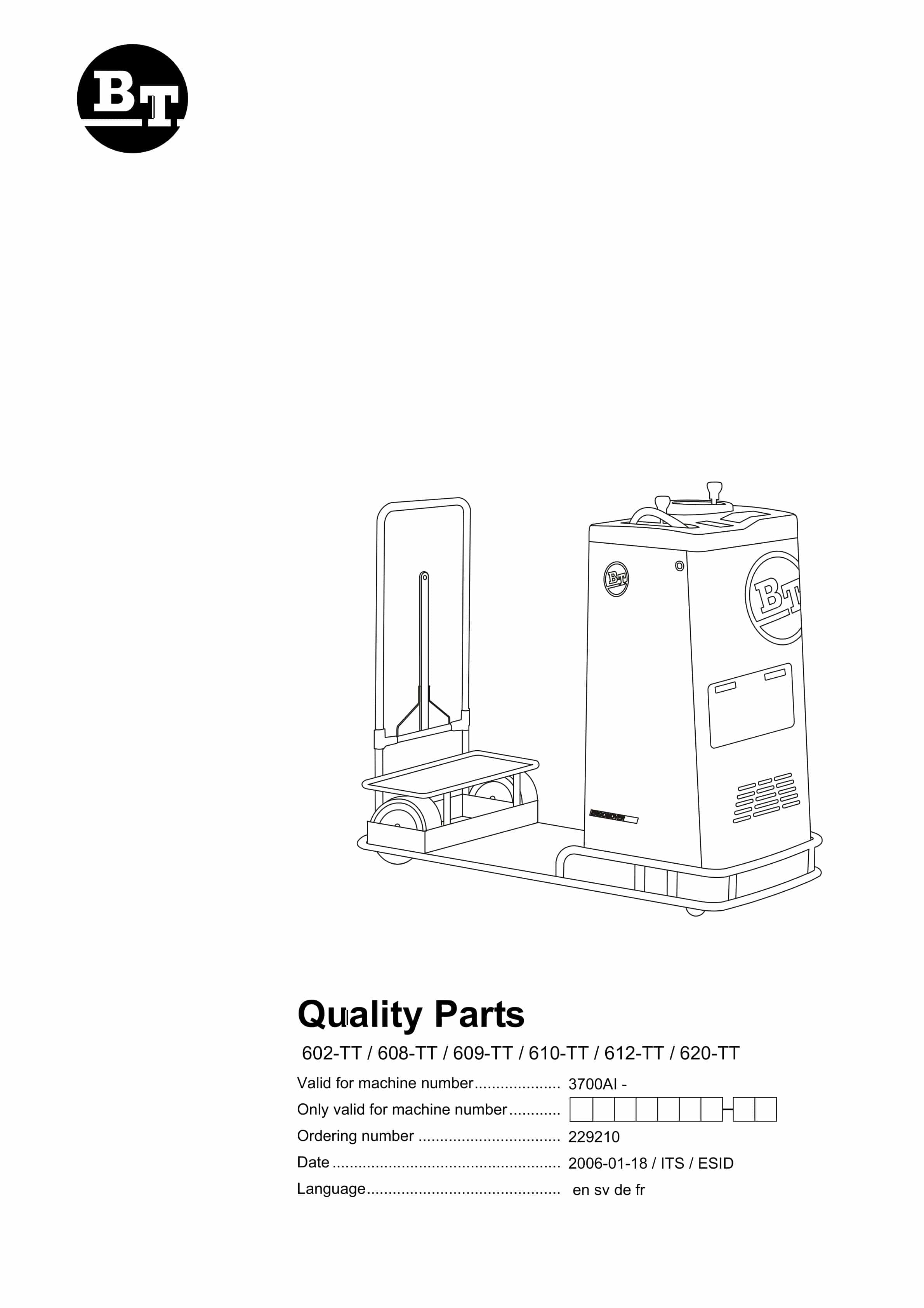
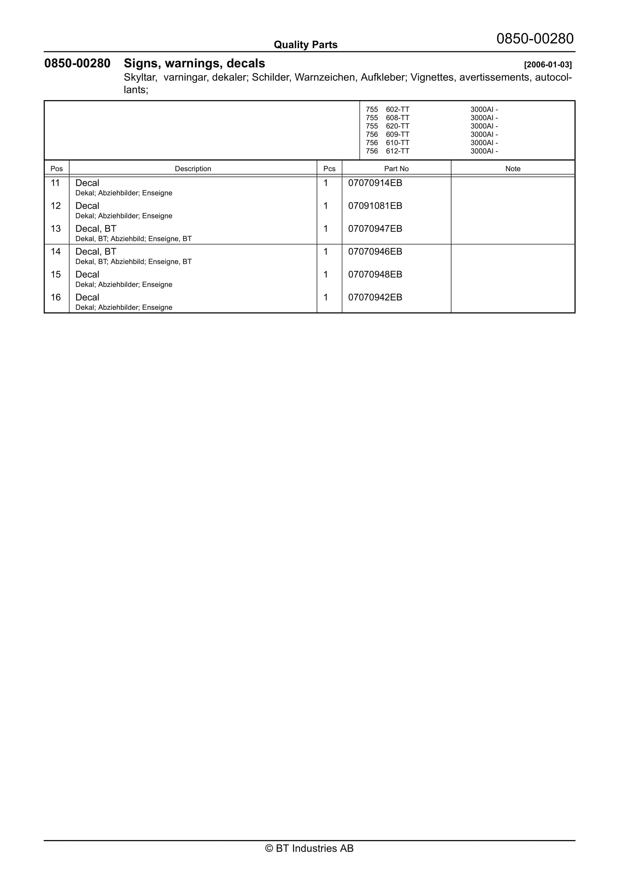
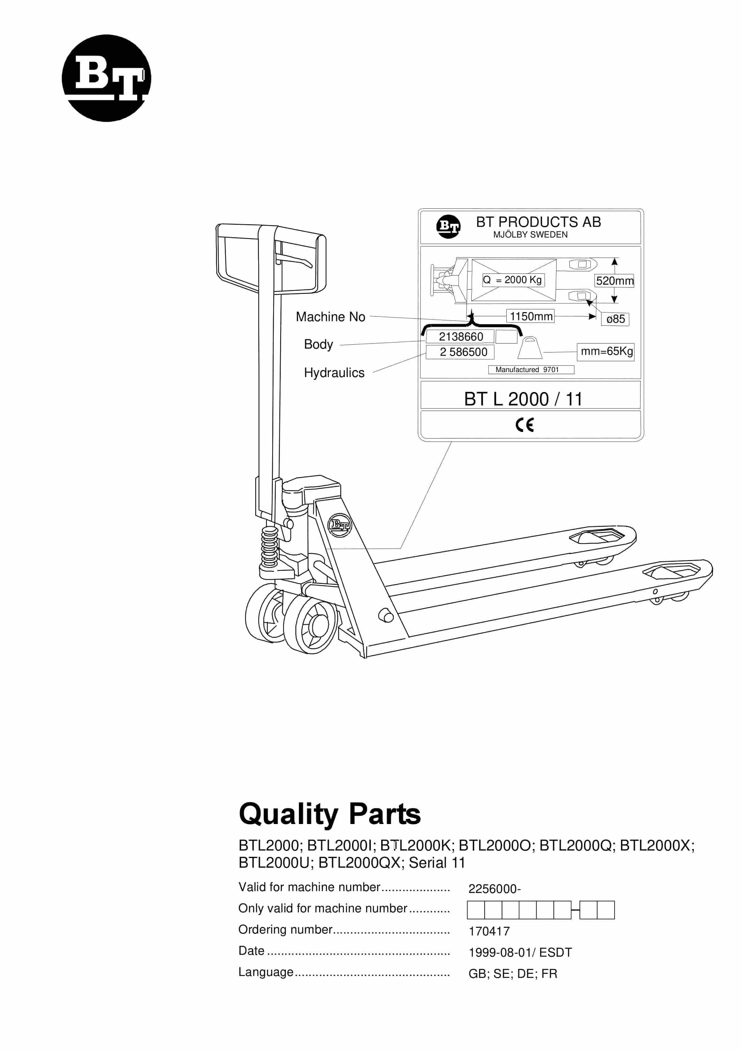
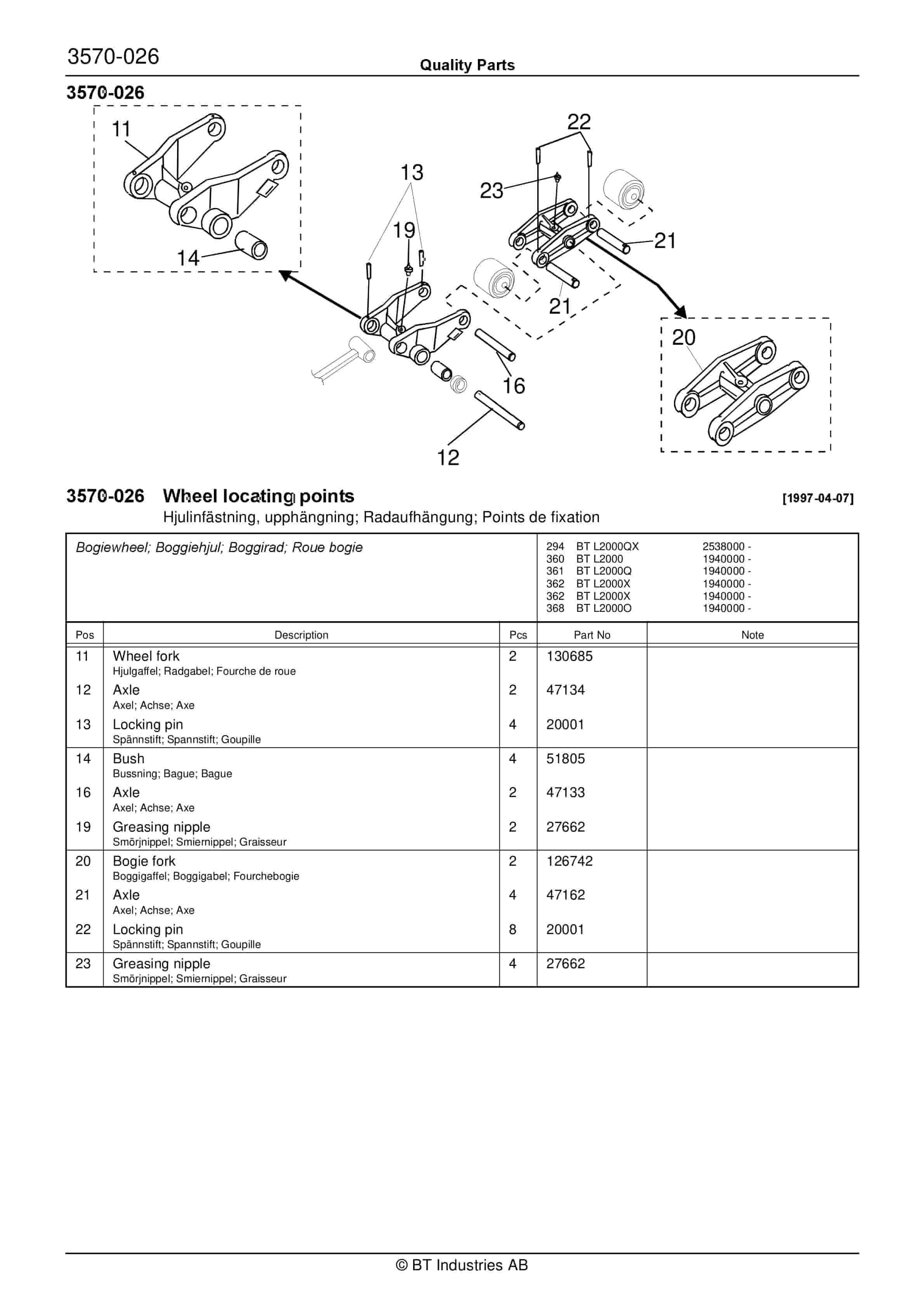
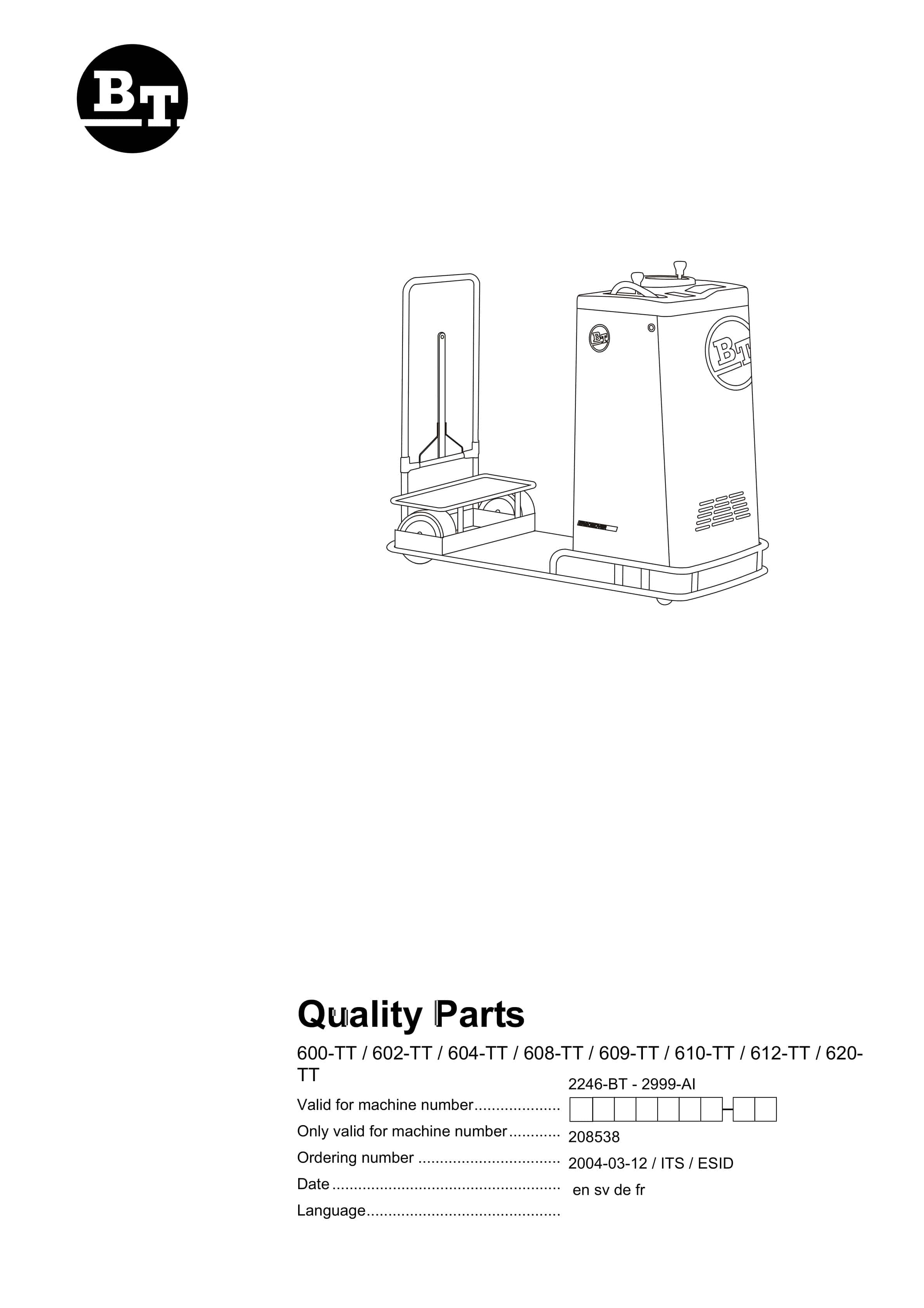
BT 600-TT, 602-TT, 604-TT, 608-TT, 609-TT, 610-TT, 612-TT, 620-TT Quality Parts 208538
$30.00
BT Parts Manual PDF
BT C3E150, C3E160, C3E160L, C3E180, C3E180L, C3E200 Spare Parts Catalog 0350202R3-0
BT Parts Manual PDF
BT 600-TT, 602-TT, 604-TT, 608-TT, 609-TT, 610-TT, 612-TT, 620-TT Quality Parts 208538